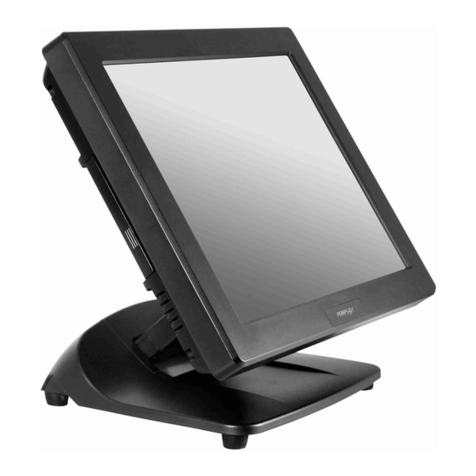
DigiPos PowerPoS User manual

DigiPoS PowerPoS & Millennium
Technical Manual
Socket 370 Series
Manual Version T1.3
October 2002

DigiPoS PowerPoS & Millennium Technical Manual
USER’S NOTICE
No part of this manual, including the products and software described in it, may be
reproduced, transmitted, transcribed, stored in a retrieval system, or translated into any
language in any form or by any means, except documentation kept by the purchaser for
backup purposes, without the express written permission of PC-PoS.
PC-PoS provides this manual “AS IS” without warranty of any kind, either express or
implied, including but not limited to the implied warranties or conditions of merchantability
or fitness for a particular purpose. In no event shall PC-PoS, its directors, officers,
employees or agents be liable for any indirect, special, incidental, or consequential
damages (including damages for loss of profits, loss of business, loss of use or data,
interruption of business and the like), even if PC-PoS has been advised of the possibility
of such damages arising from any defect or error in this manual or product.
Specifications and information contained in this manual are provided for informational use
only, and are subject to change or update at any time without notice, and should not be
construed as a commitment by PC-PoS. PC-PoS assumes no responsibility or liability for
any errors or inaccuracies that may appear in this manual, including the products and
software described in it.
Updates to this manual and additional information may be found on the Internet at
http://www.pc-pos.com/
For any drivers associated with this DigiPoS, please contact your supplier/distributor or
you can find the latest versions available for download on the Internet at
http://www.pc-pos.com
FCC Radio Frequency Interference Statement
This equipment has been tested and found to comply with the limits for a class A digital
device. These limits are designed to provide reasonable protection against harmful
interference when the equipment is operated in a commercial environment. This
equipment generates, uses and can radiate radio frequency energy and, if not installed
and used in accordance with the instruction manual, may cause harmful interference to
radio communications. Operation of this equipment in a residential area is likely to cause
harmful interference, in which case the user will be required to correct the interference at
this own expense.
Notice
The changes or modifications not expressly approved by the party responsible for
compliance could void the user’s authority to operate the equipment.
All brand names and registered trademarks mentioned in this manual are the property of
their respective owners and their use here is for reference purposes only.
Page 2 of 2

DigiPoS PowerPoS & Millennium Technical Manual
SAFETY INSTRUCTIONS
• Always read the safety instructions carefully.
• Keep this Manual for future reference.
• Keep this equipment away from humidity and dust.
• Lay the equipment on a reliable flat surface before setting it up.
• The openings on the enclosure are for air convection, hence protecting the equipment
from overheating. DO NOT COVER THESE OPENINGS. For a more detailed
explanation about ventilation requirements, please check the on-line documentation
available at:
http://www.pc-pos.com/
• Make sure the voltage of the power source (mains) conforms within the permitted
range before connecting the equipment to the power inlet.
• Place the power cord in such a way that people cannot step on it. Do not place
anything over the power cord.
• ALWAYS shut down the operating system and disconnect the unit from any power
sources before removing any connections (Keyboard, Mouse, etc..) or opening up the
unit to fit additional cards and or devices.
• All cautions and warnings on the equipment should be noted and adhered to.
• Never pour any liquid into the opening that could damage or cause electrical shock.
• If any of the following situations arise, have the equipment checked by qualified service
personnel:
oThe power cord or plug is damaged
oLiquid has penetrated into the DigiPoS
oThe equipment has been exposed to moisture
oThe DigiPoS is not working well or you can not get it to work according to the
User’s Manual
oThe DigiPoS has been dropped and damaged
oThe DigiPoS has obvious signs of breakage or physical damage
• Do not leave this DigiPoS in a non air-conditioned environment with a storage
temperature above 60ºc (140ºf) as it may damage the equipment.
• For reasons of safety, gloves should be worn when assembling the DigiPoS after any
work has been carried out.
NOTE
• The technical descriptions and specifications of the Millennium & PowerPoS are
subject to change without notice.
ACHTUNG!
• Wir behalten uns Änderungen der technischen Beschreibungen bzw.
Spezifikationen vor.
• ,.
• ,PC.
Page 3 of 3

DigiPoS PowerPoS & Millennium Technical Manual
CAUTION
There is a danger of explosion if the CMOS battery is incorrectly replaced.
Replace only with the same or equivalent type of battery. Please Contact you’re
nearest PC-PoS office for further information and or assistance.
Page 4 of 4

DigiPoS PowerPoS & Millennium Technical Manual
CONTENTS
Introduction .......................................................................................................................8
Key Features ...................................................................................................................8
Ventilation Requirements...............................................................................................10
Cavity Size.....................................................................................................................10
Enclosed Spaces...........................................................................................................10
External PSU.................................................................................................................10
Under Counter Mounting................................................................................................11
DigiPoS Brackets...........................................................................................................11
Technical Specifications ................................................................................................12
CPU & FSB Clock Speeds.............................................................................................12
Memory .........................................................................................................................12
BIOS..............................................................................................................................12
VIA 82C686B ‘South Bridge’..........................................................................................13
PCI to ISA Bridge.......................................................................................................13
UltraDMA-33 / 66 / 100 Master Mode PCI EIDE Controller........................................13
Integrated Super IO Controller ...................................................................................14
Voltage, Temperature, Fan Speed Monitor and Controller ........................................14
Universal Serial Bus Controller ..................................................................................14
System Management Bus Interface...........................................................................14
PC99-Compatible Power Management......................................................................14
Plug and Play Controller ............................................................................................15
VIA VT8604 ‘North Bridge’.............................................................................................15
General ......................................................................................................................15
Advanced, High-Performance Memory Controller......................................................16
Accelerated Graphics Port (AGP) Controller..............................................................16
Integrated Savage4 2D/3D/Video Accelerator ...........................................................16
3D Rendering Features..............................................................................................16
2D Hardware Acceleration Features ..........................................................................17
Motion Video Architecture..........................................................................................17
Flat Panel Monitor Support ........................................................................................17
Concurrent PCI Bus Controller...................................................................................17
Full Software Support ................................................................................................17
Onboard Audio ..............................................................................................................17
Onboard LAN Adapter ...................................................................................................18
Options ..........................................................................................................................18
PCI Cards ..................................................................................................................18
Disk On Module Port..................................................................................................18
Dual VGA out card .....................................................................................................18
CD-ROM/ CD-R/ CD-RW ...........................................................................................18
Page 5 of 5

DigiPoS PowerPoS & Millennium Technical Manual
Digital Flat Panel Output (DVI)...................................................................................18
Important Notes .............................................................................................................19
The System......................................................................................................................20
Front Panel Orientation .................................................................................................20
Rear Panel Orientation ..................................................................................................21
Internal System Orientation ...........................................................................................22
The Heat Pipe, Air Tunnel & CPU .................................................................................23
Jumper Settings and Connections.................................................................................26
Jumpers .....................................................................................................................26
CPU Switch Settings..................................................................................................26
Connections...............................................................................................................27
Riser Card Orientation...................................................................................................27
Motherboard Orientation................................................................................................27
Motherboard Orientation................................................................................................28
I/O Interfaces & Power Connectors ...............................................................................29
I/O Interfaces & Power Connectors ...............................................................................30
RS232 Standard Serial Ports.....................................................................................30
Parallel Port ...............................................................................................................30
USB Ports ..................................................................................................................31
PS / 2 Keyboard & Mouse Ports ................................................................................31
LAN Connector ..........................................................................................................32
VGA Connector..........................................................................................................33
Hosiden Connector ....................................................................................................33
Power Supply Connector ...........................................................................................33
2.5mm Barrel Connector............................................................................................34
Power Distribution on the Millennium & Power PoS....................................................35
Configuration .................................................................................................................35
Correct Fuse Ratings .................................................................................................36
Power Board Configuration........................................................................................36
Application .................................................................................................................36
Typical Voltage Requirements ...................................................................................37
Continuous and Peak Current Capacity.....................................................................37
Onboard Diagnostics for the Millennium & Power PoS...............................................38
Diagnostic Overview......................................................................................................38
Diagnostic Procedure.................................................................................................38
Printer Test ................................................................................................................39
Customer Display Test...............................................................................................39
Keyboard Test............................................................................................................40
Magnetic Card Test....................................................................................................41
Bar Code Scanner Test .............................................................................................42
Page 6 of 6

DigiPoS PowerPoS & Millennium Technical Manual
BIOS Set-up Overview ....................................................................................................43
Main BIOS Screen.........................................................................................................44
Details........................................................................................................................44
Standard CMOS Features .............................................................................................45
General Details ..........................................................................................................45
IDE Options Sub Menus.............................................................................................47
Details........................................................................................................................47
Advanced BIOS Features..............................................................................................49
Details........................................................................................................................49
Advanced Chipset Features ..........................................................................................52
Details........................................................................................................................52
Integrated Peripherals ...................................................................................................54
Details........................................................................................................................54
Power Management Setup ............................................................................................58
Details........................................................................................................................58
Power Management Sub Menu..................................................................................59
Wake Up Events Sub Menu.......................................................................................60
PnP/PCI Configurations.................................................................................................61
Details........................................................................................................................61
PC Health Status ...........................................................................................................63
Details........................................................................................................................63
Frequency/Voltage Control............................................................................................64
Details........................................................................................................................64
Operating System Dependant Settings .........................................................................65
DOS ...........................................................................................................................65
Windows 95 & NT ......................................................................................................66
Windows 98, Me, 2000 & Xp......................................................................................66
Windows Xp Special Notes........................................................................................66
WARRANTY POLICY.......................................................................................................67
Limited Warranty ...........................................................................................................67
Warranty Return Procedures.........................................................................................67
THE FOLLOWING SHALL VOID WARRANTY .............................................................67
PC-PoS Global Office Locations....................................................................................68
Page 7 of 7

DigiPoS PowerPoS & Millennium Technical Manual
Introduction
Congratulations on the purchase of your DigiPoS Retail System!
You are now the owner of a state-of-the-art DigiPoS Retail System. The DigiPoS Retail
System is a solution that offers enhanced features, speed and performance combined with
exceptional reliability. It is also a PC that is unrivalled by other conventional Pentium
based PCs within the EPoS industry.
Key Features
Component Description
CPU Supports Socket 370 Intel Celeron / PIII/VIA Cyrix C3 CPUs
CPU CLOCK 266 MHz to 1GHz
MAIN MEMORY Notebook SO-DIMM X 1 up to 512MB (SDRAM or EDO)
BIOS
Enhanced ACPI 1.0 / PnP / APM / DMI / ESCD / PCI bus 2.1 / OnNow /
DRAM ECC Quick Boot / HW Monitor (LDCM) / I-O Pre-set IRQ / Spread
Spectrum / PC98 compliant
CACHE MEMORY 512KB P.B. SRAM
EXPANSION SLOTS Riser Card with 3 FREE Slots:
1 x ISA, 2 x PCI and 1 x IDE2 CD-ROM connector
SERIAL PORTS COM1, COM2, COM3, COM4 (COM3/4 output on riser card).
IRQ & I/O address selection by BIOS (Jumper less).
PARALLEL PORT One LPT port (SPP / EPP / ECP) IRQ and address selectable by BIOS
USB TWO USB ports supporting Windows 95/98/Me/2000/Xp
FDD 1.44MB / 3.5" FDD x 1
ENHANCED PCI IDE On board PCI Bus Master IDE1/2 controller with Windows utility.
Supports Ultra DMA/66
AGP GRAPHICS
ADAPTER
VIA 8604 AGP with shared memory from 2MB up to 32MB.
Features include:
Support for 4X AGP VGA controller
Support for 3D / 2D Graphics Accelerator
Support for DVD Video Accelerator
Support for VESA DPMS VGA Monitor for Power Management
Direct X, VPE, MPEG2
NT4.0 / 5.0, Windows95/98/Me/2000/Xp utility
APM / ACPI 1.0
Supports VESA DPMS VGA monitor for power management
PC98 compliant
CRT and LCD TMDS output (Optional)
Supports dual monitor output (optional) under Windows 98/Me/2000/Xp
ONBOARD LAN
(10/100Mbs
Auto sensing)
ACPI / NT4.0 / 5.0 (NDIS 5)
NT 4.0 / Win95/98 utility
Remote boot ROM
NT4.0/Win95/98 Utility
PC98 compliant
Enable or disable by BIOS set-up (Jumper less)
ONBOARD AUDIO AC97 CODEC on board
Page 8 of 8

DigiPoS PowerPoS & Millennium Technical Manual
DISK ON CHIP With DigiPoS EPoS Diagnostics Utility
Component Description
KEYBOARD PORT PS/2 type
MOUSE PORT PS/2 type
FRONT PANEL
Front panel features include:
AC power on/off button
3 LED indicators: Power On/Off, HDD state & LAN state
1.44MB FDD
Door for FDD and Power switch (with key lock)
Slim 24X CD-ROM or CD-R/ CD-RW (optional) drive bay
BACK PANEL
Back panel features include:
VGA CRT 15-pin DSUB connector
COM1/2/3/4 9-pin DSUB output connectors
LPT 25-pin DSUB connector
PS/2 Keyboard & Mouse connectors
LAN RJ-45 output connector
USB1 / USB2 connector
Audio line in / line out, microphone-in
2nd CRT and LCD TMDS output (optional)
TV S-Video and RCA connector output (optional)
THERMAL SOLUTION
One low-noise 50mm fan for power supply and HDD
One low-noise 50mm fan for CPU heat-pipe (water cooling system)
and air tunnel
AC POWER SUPPLY 300W External Power Supply
(UL, CSA, VDE, EMI meets FCC *B*)
AC POWER SOURCE AC 90V to 264V, 60Hz / 50Hz
CASE DIMENSIONS 11"(W) x 11" (D) x 3" (H) (280 x 280 x 75mm)
(Excluding PSU)
S/W COMPATIBILITY DOS / OS2 V2.1 / SCO XENIX: V2.3.2 / SCO UNIX V3.2 / NOVELL /
WIN 3.1/95/98/Me/NT4.0/2000/Xp
EXPORT PACKAGING Each pack measures 36 x 36 x 19cm and weighs 5.5kg net 6.5kg gross
TEMPERATURE Operating: 0ºC to 40ºC (without HDD up to 50ºC)
Storage: -25ºC to 70ºC
Page 9 of 9

DigiPoS PowerPoS & Millennium Technical Manual
Ventilation Requirements
Cavity Size
If the DigiPoS is to be located in a cavity, i.e. under the counter, the cavity dimensions
must be a minimum of 380mm long by 400mm wide by 120mm deep (excluding the
external PSU). A diagrammatic representation is as follows:
120mm
400mm
Although this is the required space, the DigiPoS MUST be located centrally to prevent the
airflow from being disrupted through the ventilation holes in the sides of the case.
Enclosed Spaces
If the DigiPoS is to be located in an enclosed space, i.e. in a closed box or cabinet, there
must be sufficient airflow into and out of the enclosed space. Using the above cavity
space as an example, forced airflow would have to be fitted to prevent the DigiPoS from
overheating. As a general rule, the PowerPoS & Millennium require an airflow exchange
rate of a minimum of 25 CFM (Cubic Feet per Minute) excluding PSU or 30 CFM including
PSU when in an enclosed space.
The recommended location for these fans is as follows:
Vie w Fro m Ab o ve
Airflow
Direc tio n
Airflow
Direc tio n
25cfm Fan
Exh a u st Ve n t
DigiPoS
Fro n t
Re a r
Excluding PSU
Vie w Fro m Ab o ve
Airflow
Direc tion
Airflow
Direc tion
30cfm Fan
Exh a u st Ve n t
DigiPoS
Fro n t
Re a r
PSU
Including PSU
External PSU
PC-PoS recommends that the external PSU for the PowerPoS & the Millennium are not
situated in the same space as the DigiPoS to minimise heat build up in enclosed spaces.
If this is unavoidable, forced air ventilation must be installed to provide adequate
ventilation for the DigiPoS & PSU heat dissipation devices.
Page 10 of 10

DigiPoS PowerPoS & Millennium Technical Manual
Under Counter Mounting
The DigiPoS can be mounted under the counter or on a secure vertical surface to
maximise the available space at the Point of Sale. In order to do this, a special bracket
must be used that has been specifically engineered for the DigiPoS. This bracket does not
obstruct the ventilation yet still provides a secure mounting without the need for drilling
holes in the case which will void the warranty.
DigiPoS Brackets
To fit the bracket, simply remove the case screw towards the rear of the DigiPoS and offer
up the bracket to the DigiPoS. Then, refit the screw and the DigiPoS can now be secured
in position.
The External PSU has mounting holes pre-formed in its case and does not require any
special brackets.
Please contact you’re nearest PC-PoS Office for further details and availability on these
brackets.
Page 11 of 11

DigiPoS PowerPoS & Millennium Technical Manual
Technical Specifications
CPU & FSB Clock Speeds
The Central Processing Unit or CPU fitted in your DigiPoS will depend greatly on what
particular model of DigiPoS you have. The Following is a detailed list of the correct type
of CPU fitted to each model and their respective settings:
DigiPoS Millennium DigiPoS PowerPoS
CPU Type Intel Celeron
Package Type FC-PGA
(Flip Chip - Pin Grid Array)
Clock Speed 850Mhz
Front Side Bus Speed 100Mhz
L2 Cache Size 128Kb
CPU Type Intel PIII
Package Type FC-PGA
(Flip Chip - Pin Grid Array)
Clock Speed 1Ghz
Front Side Bus Speed 133Mhz
L2 Cache Size 256Kb
(Advanced Transfer Cache)
The thermal transfer pad on CPU heat pipe assembly can be easily damaged if the
heat pipe is removed and refitted several times. We therefore recommend that only
PC-PoS or authorized agents for PC-PoS attempt to remove the heat pipe. Failure to
comply with this notice shall void all warranties.
Memory
Each DigiPoS, Millennium or PowerPoS, is fitted with a single module of memory.
Commonly referred to as laptop memory, the correct terminology for it is Small Outline
Dual In-line Memory Module or SODIMM for short. The specifications for this memory are
as follows:
Pins 144 Pin Gold
Type SDRAM
Sizes 32, 64, 128, 256, 512Mb
32, 64Mb 100Mhz
Clock Speeds*
128, 256, 512Mb 100 – 133Mhz
*= Dependant on Front Side Bus setting according to CPU type.
Should you wish to upgrade the memory in the DigiPoS, please contact PC-PoS for
the specifications on the correct type of memory to be used. Using inappropriate
types of memory may significantly degrade the performance of your DigiPoS and
also void all warranties.
BIOS
The Phoenix BIOS is discussed in greater detail later on in this manual.
Page 12 of 12

DigiPoS PowerPoS & Millennium Technical Manual
VIA 82C686B ‘South Bridge’
Incorporating:
• PCI Expansion Slots
• ISA Expansion Slots
• IDE Ports
• Keyboard & Mouse Ports
• RS232 ‘Serial’ Ports
• Parallel Port
• USB Ports
• Hardware Monitoring
• Motherboard Resources
PCI to ISA Bridge
• Integrated ISA Bus Controller with integrated DMA, timer, and interrupt
controller
• Integrated Keyboard Controller with PS2 mouse support
• Integrated DS12885-style Real Time Clock with extended 256byte
CMOS RAM and Day/Month Alarm for ACPI
• Integrated USB Controller with root hub for 2 ports
• Integrated UltraDMA-33/66/100 master mode EIDE controller with
enhanced PCI bus commands
• PCI-2.2 compliant with delay transaction and remote power management
• Eight double-word line buffer between PCI and ISA bus
• One level of PCI to ISA post-write buffer
• Supports type F DMA transfers
• Distributed DMA support for ISA legacy DMA across the PCI bus
• Serial interrupt for docking and non-docking applications
• Fast reset and Gate A20 operation
• Edge trigger or level sensitive interrupt
• Flash EPROM, 4Mb EPROM and combined BIOS support
• Supports positive and subtractive decoding
UltraDMA-33 / 66 / 100 Master Mode PCI EIDE Controller
• Dual channel master mode PCI supporting multiple Enhanced IDE
devices
• Transfer rate up to 33MB/sec to cover PIO mode 4, multi-word DMA
mode 2 drives, and UltraDMA-33 interface
• Increased reliability using UltraDMA-66 transfer protocols
• Increased performance using UltraDMA-100 mode 5
• Thirty-two levels (double words) of pre-fetch and write buffers
• Dual DMA engine for concurrent dual channel operation
• Bus master programming interface for SFF-8038I rev.1.0 and Windows-
95 compliant
• Full scatter gather capability
• Support ATAPI compliant devices including DVD devices
• Support PCI native and ATA compatibility modes
• Complete software driver support
Page 13 of 13

DigiPoS PowerPoS & Millennium Technical Manual
Integrated Super IO Controller
• Supports 4 serial ports, parallel port, and floppy disk controller functions
• Programmable character lengths (5,6,7,8)
• Even, odd, stick or no parity bit generation and detection
• Programmable baud rate generator
• Independent transmit/receiver FIFOs
• Modem Control
• Plug and play with 96 base IO address and 12 IRQ options
• Multi-mode parallel port
oStandard mode (SPP), ECP and EPP support
• Floppy Disk Controller
• 16 bytes of FIFO
• Data rates up to 1Mbps
• Perpendicular recording driver support
• Plug and play with 48 base IO address, 12 IRQ and 4 DMA options
Voltage, Temperature, Fan Speed Monitor and Controller
• Monitoring of Five positive voltages (one internal), three temperatures
(one internal) and two fan-speed (CPU & PSU)
• Programmable control, status, monitoring and alarm facility for flexible
desktop thermal management
• Automatic clock throttling with integrated temperature sensing
• Internal core VCC voltage sensing
Universal Serial Bus Controller
• USB v.1.1 and Intel Universal HCI v.1.1 compatible
• Eighteen level (double words) data FIFO with full scatter and gather
capability
• Root hub and 2 functioning ports
• Integrated physical layer transceivers with optional over-current detection
status on USB inputs
• Legacy keyboard and PS/2 mouse support
System Management Bus Interface
• Host interface for processor communications
• Slave interface for external SMBus masters
PC99-Compatible Power Management
• CPU clock throttling and clock stop control for complete ACPI C0 to C3
state support
• PCI bus clock run, Power Management Enable (PME) control, and
PCI/CPU clock generator stop control
• Supports multiple system suspend types: power-on suspends with
flexible CPU/PCI bus reset options,
• suspend to DRAM, and suspend to disk (soft-off), all with hardware
automatic wake-up
• Multiple suspend power plane controls and suspend status indicators
• One idle timer, one peripheral timer and one general purpose timer, plus
24/32-bit ACPI compliant timer
Page 14 of 14

DigiPoS PowerPoS & Millennium Technical Manual
PC99-Compatible Power Management Cont.
• Normal, doze, sleep, suspend and conserve modes
• System event monitoring with two event classes
• Primary and secondary interrupt differentiation for individual channels
• Dedicated input pins for power/ sleep buttons and external modem ring
indicator
• Up to 12 general purpose input ports and 23 output ports
• Multiple internal and external SMI sources for flexible power
management models
• One programmable chip select and one micro controller chip select
• Enhanced integrated real time clock (RTC) with date alarm, month alarm,
and century field
• Thermal alarm on either external or any combination of three internal
temperature-sensing circuits
• I/O pad leakage control
Plug and Play Controller
• PCI interrupts steerable to any interrupt channel
• Steerable interrupts for integrated peripheral controllers: USB, floppy,
serial, parallel, audio, SoundBlaster, MIDI
• Steerable DMA channels for integrated floppy, parallel, and SoundBlaster
pro controllers
• One additional steerable interrupt channel for on-board plug and play
devices
• Microsoft Windows 95, Windows 98, Windows Me, Windows 2000 and
Windows Xp Plug and Play BIOS compliant
VIA VT8604 ‘North Bridge’
Incorporating:
• CPU Interface
• Memory Controller
• AGP Graphics Controller
• PCI Bus Controller
General
• High performance SMA North Bridge
• Integrated VIA Apollo Pro133A and S3. Savage4. in a single chip
• “P6-bus Desktop PC” member of VIA’s Apollo ProSavage integrated
graphics product line
• 64-bit Advanced Memory controller supporting PC100/PC133 SDRAM
and VCM
• High Performance CPU Interface
• Socket 370 (VIA Technologies VIA-Cyrix-III. and Intel Celeron.)
• 66/100/133 MHz CPU Front Side Bus (FSB)
• Built-in Phase Lock Loop circuitry for optimal skew control within and
between clocking regions
Page 15 of 15

DigiPoS PowerPoS & Millennium Technical Manual
General Cont
• Five outstanding transactions (four In-Order Queue (IOQ) plus one
output latch)
• Dynamic deferred transaction support
Advanced, High-Performance Memory Controller
• DRAM interface runs synchronous (66/66, 100/100, 133/133) mode or
pseudo-synchronous (66/100, 100/66, 100/133, 133/100) mode with FSB
(for 66 / 66 operation, only external VGA is supported)
• Concurrent CPU, AGP, and PCI access
• Supports maximum 8-bank interleave (8 pages open simultaneously);
banks are allocated based on LRU
• SDRAM X-1-1-1-1-1-1-1 back-to-back accesses
Accelerated Graphics Port (AGP) Controller
• AGP Specification Rev. 2.0 compliant
• Supports 266 MHz 4x mode for AD and SBA signalling
• Supports Sideband Addressing (SBA) mode (non-multiplexed
address/data)
• Pipelined split-transaction long-burst transfers up to 1GB/sec
• Intelligent request reordering for maximum AGP bus utilization
Integrated Savage4 2D/3D/Video Accelerator
• Optimised Shared Memory Architecture (SMA)
• 2 to 32 MB frame buffer using system memory
• Floating-point triangle set-up engine
• Single cycle 128-bit 3D architecture
• 8M-triangles/ second set-up engine
• 140M-pixels/ second tri-linear fill rate
• Full AGP 4x, including sideband addressing and execute mode
• S3 DX7 texture compression (S3TC)
• Next generation, 128-bit 2D graphics engine
• High quality DVD video playback (With DVD Drive)
• Flat panel monitor support
• 2D/3D resolutions up to 1920 x 1440
3D Rendering Features
• Single-pass multiple textures
• Anisotropic filtering
• 8-bit stencil buffer
• 32-bit true colour rendering
• Specular lighting and diffuse shading
• Alpha blending modes
• Massive 2K x 2K textures
• MPEG-2 video textures
• Vertex and table fog
• 16 or 24-bit Z-buffering
• Reflection mapping, texture morphing, shadows, procedural textures and
atmospheric effects
Page 16 of 16

DigiPoS PowerPoS & Millennium Technical Manual
2D Hardware Acceleration Features
• ROP3 Ternary Raster Operation BitBLTs
• 8, 16, and 32 bpp mode acceleration
Motion Video Architecture
• High quality up/down adjustment
• Planar to packed format conversion
• Motion compensation for full speed DVD playback
• Hardware sub-picture blending and highlights
• Multiple video windows for video conferencing
• Contrast, hue, saturation, brightness and gamma controls
Flat Panel Monitor Support
• 12-bit digital interface for Flat Panel encoders
• Auto-expansion and centering for VGA modes
• Support for all resolutions up to 1280x1024
• Digital Visual Interface (DVI) 1.0 compliant
Concurrent PCI Bus Controller
• PCI 2.2 compliant, 32-bit 3.3V PCI interface with 5V tolerant inputs
• Supports up to 5 PCI masters
• PCI to system memory data streaming support
• Delay transaction from PCI master accessing DRAM
• Symmetric arbitration between Host/PCI bus for optimised system
performance
Full Software Support
• Drivers for major operating systems and APIs including
oWindows 9x
oWindows NT 4.0
oWindows 2000
oWindows 3.x
oOS/2 2.1/3.0 (Warp)
oLinux
• Direct3D, DirectDraw and DirectShow OpenGL ICD for Windows 9x, NT,
2000 and Xp
• North Bridge/Chipset and Video BIOS support
Onboard Audio
• AC’97 2.1 compliant codec
• 18-bit stereo full duplexcodec
• VSR (Variable Sampling Rate), 1Hz resolution
• 3D stereo expansion for simulated surround sound
• 1 stereo analog line-level input
• 1 mono analog line-level input
• 1 line-level output with volume control
• Multiple codec mode
• Low Power consumption mode
• Exceeds Microsoft® PC’9x requirements
Page 17 of 17

DigiPoS PowerPoS & Millennium Technical Manual
Onboard LAN Adapter
• Integrated Fast Ethernet MAC, Physical chip and transceiver in one chip
• 10 Mb/s and 100 Mb/s operation
• Supports 10 Mb/s and 100 Mb/s N-way Auto-negotiation operation
• PCI local bus single-chip Fast Ethernet controller
oCompliant to PCI Revision 2.2
oSupports PCI target fast back-to-back transaction
oProvides PCI bus master data transfers and PCI memory space or I/O
space mapped data transfers of RTL8139C (L)'s operational registers
oSupports PCI VPD (Vital Product Data)
oSupports ACPI, PCI power management
• Supports CardBus. The CIS can be stored in 93C56 or expansion ROM
• Supports up to 128K bytes Boot ROM interface for both EPROM and Flash
memory
• Supports 25MHz crystal or 25MHz OSC as the internal clock source. The
frequency deviation of either crystal or OSC must be within 50 PPM.
• Compliant to PC99 standard
• Includes a programmable, PCI burst size and early Tx/ Rx threshold.
• Supports a 32-bit general-purpose timer with the external PCI clock as clock
source, to RTL8139C (L) Preliminary generate timer-interrupt
• Contains two large (2Kbyte) independent receive and transmit FIFO’s
• Uses 93C46 (64*16-bit EEPROM) or 93C56 (128*16-bit EEPROM) to store
resource configuration, ID parameter, and VPD data. The 93C56 can also be
used to store the CIS data structure for CardBus application.
• Peer to Peer Support
• Boot Rom Socket for remote boot facility
• Half/ Full duplex capability
• Supports Full Duplex Flow Control (IEEE 802.3x)
Options
PCI Cards
Please contact your EPoS distributor or PC-PoS to discuss the wide range of PCI
card add-ons that are available to enhance your solution.
Disk On Module Port
Compact Flash card ATA IDE type I PC card socket
Dual VGA out card
2nd CRT VGA, TV and LCD TMDS add-on card
(Please contact PC-PoS for advice on the appropriate selection of this card)
CD-ROM/ CD-R/ CD-RW
Single IDE 2 Socket for 1 x Internal CD ROM
Digital Flat Panel Output (DVI)
Please contact your EPoS distributor or PC-PoS to discuss your requirements.
Page 18 of 18

DigiPoS PowerPoS & Millennium Technical Manual
Important Notes
1 For maximum performance, the cable used for the hard drive is constructed from a
special material and due care must be taken when removing or replacing this item,
taking note of the route the cable takes from the hard drive to the motherboard
connector.
2 As the power supply of this unit is an AT type, it will not support Advanced Power
Management (APM) functions. Under Windows 2000, if the APM function is enabled,
the system will not shut down correctly.
3 If the hard drive has to be replaced, only fit a hard drive that has a maximum speed
of 5400rpm. For the correct type and options available, please contact PC-PoS.
4 The only connectors that can be unplugged while the DigiPoS is powered are the
USB connectors. If any other connector is removed or replaced while the power is
on, serious damage can occur to the DigiPoS. This is considered to be outside the
scope of the warranty and will attract a charge for the repair of any damage caused
by this action.
5 The installation of an internal CD-ROM will determine the maximum card length used
in the 32-bit PCI SLOTS located in PCI 1/PCI 2 because of the compact nature of the
DigiPoS. The length of any PCI add-on card is as follows:
5.1 190mm long x 110mm wide without CD-ROM
5.2 140mm long x 110mm wide with CD ROM
5.3 The ISA SLOT has a maximum length of any add-on card of 170mm long x
110mm wide.
Page 19 of 19

DigiPoS PowerPoS & Millennium Technical Manual
The System
The following information will help you to acquaint yourself with the external & internal
components of the DigiPoS Retail System.
Front Panel Orientation
(Shown with front panel down)
123 456 7 8
10 11 12 13 14
9
1. LED- Power On Indicator
2. LED- LAN Status Indicator
3. LED- HDD Activity Indicator
4. Front Panel & CD ROM Lock
5. LED- DigiPoS Diagnostics Disk On Chip Active
6. LED- Power Distribution Board Voltages
7. LED- FDD Activity Indicator
8. FDD Drawer
9. FDD Release Button
10. CD ROM (Optional)
11. LED- CD ROM Activity Indicator
12. CD ROM Drawer Open Button
13. CD ROM Manual Draw Open Catch
14. Power On / Off Switch
Note
The Front Panel Styles are different between the Power PoS and the Millennium. The
diagrams shown here are greatly simplified to enable ease of use and there may be slight
variations between these diagrams and the model you have.
Page 20 of 20
This manual suits for next models
1
Table of contents
Other DigiPos Touch Terminal manuals
Popular Touch Terminal manuals by other brands

ARMATURA
ARMATURA OmniAC30CAPQ quick start guide

Mitsubishi Electric
Mitsubishi Electric GOT 1000 Series Connection manual
VeriFone
VeriFone VX 600 Bluetooth Agnostic installation guide
POSIFLEX
POSIFLEX BB-2000 user manual
Fortec Star
Fortec Star MTX-HSPA-PH8-P+G user manual
Omron
Omron DeviceNet DRT2-ID16S-1 Specifications

