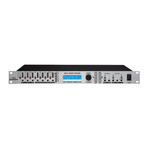
DIGISYNTHETIC DS216 User manual

DIGISYNTHETIC PRO
Instruction Manual
24-BIT DIGITAL THREE CROSSOVER PROCESSOR MODEL DS216
32BITDSP48KHZSAMPLINGRATE
DIGITAL CROSSOVER
PROGRAM PEQ
CH-SEL SETUP
OUT GAIN
STORE
INPUT B
INPUT A
2
IN B13456
CLIP
6
12
18
24
dB
-
-
-
-
-
-
-
-
-
-
-
-
-
-
-
-
-
-
-
-
30
-
IN A
36
-
3
-
dB
MUTE
CLIP
LIMIT
12
18
24
-
-
-
30
-
36
-
PARAMETER
CROSSOVER
MODE
INPUTS OUTPUTS
MUTE
CLIP
LIMIT
12
18
24
-
-
-
30
-
36
-
MUTE
CLIP
LIMIT
12
18
24
-
-
-
30
-
36
-
MUTE
CLIP
LIMIT
12
18
24
-
-
-
30
-
36
-
MUTE
CLIP
LIMIT
12
18
24
-
-
-
30
-
36
-
MUTE
CLIP
LIMIT
12
18
24
-
-
-
30
-
36
-
POWER
CROSSOVER
2~6 WAY OUT
DIGISYNTHETIC
D 216S

ATTENTION!
All DIGISYNTHETIC PRO products are carefully packed and designed to protect the units from rough handling
before shipping out from the factory. Examine your good upon receiving, to ensure no damage during transportation.
Any damage claim should be inform & notify to relative dealer within 14 days of good received. The dealer
will not except failing of such. The consignee must make all shipping claims.
The DS216 fits into a standard 19" rack unit of space (1 3/4"). Allow at least an additional 4" depth for the
connectors on the back panel. Be sure that there is enough air space around the unit for cooling and ventilation.
DO NOT place the DS216 on high temperature devices like power amplifiers etc. to avoid overheating.
Using a main cable and a standard IEC receptacle makes the main connection of the DS216. It meets all of the
international safety certification requirements.
Please make sure that all units have a proper ground connection. For your own safety, do not remove the ground
connection within the unit or at the supply, or fail to make this connection at all.
NOTICE: Before switching voltage for local supply requirement, correct fuse type and rate must be installed.
When the power supply is 220V/240V, fuse is 125mA; and the power supply is 110V/120V, fuse is changed
to 315mA. The switch is preseted to 220V/240V in the factory.
This machine is only intended for qualified personnel to operate & install. Do not attempt to repair and service
yourself but referred to qualified technical service personnel. The user must have sufficient electrical contact
to earth. Electrostatic charges might affect the operation of the DS216.
110V
120V
220V
240V
220V
CAUTION
THE POWER
SUPPLY CORD
SHOULD BE
DISCONNECTED
BEFORE
CHANGING
THE VOLTAGE
SELECTOR
1

DS216 Digital Three Crossover Processor
Operation Specification
Front Panel
2. INPUT-- input level indicator.
3. OUTPUT-- output level indicator.
4. LCD DISPLAY-- display work status and parameters.
5. PARAMETER ADJUSTMENT-- Encoder controller for parameter adjusting, parameters are increased by
rotating clockwise Encoder, or decreased by rotating anti-clockwise Encoder.
6. programs selection key. After pressing the key, users are able to select 10
"PR:1"~"PR:10". (show as Fig.1)
PROGRAM -- programs from
7.CH-SEL/CROSSOVER MODE-- channel selecting key/work mode selecting key. Firstly pressing the key,
to enter into the channel control status, at this time users are able to select 6 channels "CH:1"~ "CH:6"
by rotating Encoder clockwise or anti-clockwise. Pressing the key again, to enter into CROSSOVER
MODE setting, at this time, users are able to select 5 modes "M1"~ " M5" by rotating Encoder clockwise or
anti-clockwise. Pressing the key again, to return to the channel selecting.
32 BIT DSP 48KHZ SAMPLING RATE
DIGITAL CROSSOVER
PROGRAM PEQ
CH-SEL SETUP
OUT GAIN
STORE
INPUT B
INPUT A
2
IN B 13456
CLIP
6
12
18
24
dB
-
-
-
-
-
-
-
-
-
-
-
-
-
-
-
-
-
-
-
-
30
-
IN A
36
-
3
-
dB
MUTE
CLIP
LIMIT
12
18
24
-
-
-
30
-
36
-
PARAMETER
CROSSOVER
MODE
INPUTS OUTPUTS
MUTE
CLIP
LIMIT
12
18
24
-
-
-
30
-
36
-
MUTE
CLIP
LIMIT
12
18
24
-
-
-
30
-
36
-
MUTE
CLIP
LIMIT
12
18
24
-
-
-
30
-
36
-
MUTE
CLIP
LIMIT
12
18
24
-
-
-
30
-
36
-
MUTE
CLIP
LIMIT
12
18
24
-
-
-
30
-
36
-
POWER
CROSSOVER
2~6 WAY OUT
DIGISYNTHETIC
D 216S
126 85 10
11
97
Fig.1
Fig.2
1 2 3 4
8. Pressing the key in short time, to enter into PEQ editing status (show as Fig.2).PEQ --
At this time, users are able to select 3 Filters "FLT:1~ FLT:3" by rotating Encoder clockwise or anti-clockwise.
at the status, press Encoder to enter into the Filter parameters "Q" (bandwidth) selection. Users
are able to select 11 "Q" values (range:0.5~10) by rotating Encode clockwise or anti-clockwise.
PR:1 M1:2X2W+2S
CH:1 GN: +12.0 dB
CH:1 FLT:1 Q: 3.0
F:200Hz :+5 dB
1.INPUTA&INPUTB--input level adjustable range:- ~ +12dB
8
2

. crossover parameter setting key. Firstly pressing the key to enter into HIGH-PASS Filter type9SETUP--
setting (show as Fig.4a)
Fig.3
Fig.4a
Pressing the Encoder again, to enter into the Filter parameter "F" (Frequency) selection. Users are able
to select 24 ISO frequencies (rang:100Hz~20kHz) by rotating the Encoder clockwise or anti-clockwise.
if pressing the Encoder again, to enter into the Filter parameter "G" (Gain) adjusting. Users are able
to adjust "G" value from -12dB ~ + 12B (step is 1dB)by rotating the Encoder clockwise or anti-clockwise
if pressing the Encoder again, it will return to "FLT" status, by rotating the Encoder alsoto adjust another Filter
It is able to recycle such operation. If
PEQ status.(show as Fig.2)
press the PEQ key again, then the three Filters into FLAT status
(show as Fig.3).If press the PEQ key again, then return to
In short words, the step of Filter PEQ adjusting is following:
Press 8 Rotate 5 Press 5 Rotate 5 Press 5 Rotate 5 Press 5 Rotate 5 Press 5
Press 8
FLT FLT QQ
FF
GG
Users are able to select 3 kinds of Filter curve types ("-12dB", "-18dB", "-24dB") by rotating Encoder
clockwise or anti-clockwise. At this time, if pressing Encoder, it is able to select the cut frequency
(Rang:20Hz (show as Fig.4b).~20kHz)
Fig.4b
FLAT
CH:1 FLAT Q:3.0
F : 500Hz :+5dB
CH:1 HIGH-PASS
RESP/Q : -24dB
CH:1 HIGH-PASS
FREQ: 20Hz
3

Fig.4d
Fig.4e
Fig.4c
If press the key second time, enter into LOW-PASS Filter type setting, users are able to select 3 kinds
of Filter curve types ("-12dB", "-18dB", "-24dB") by rotating Encoder clockwise or anti-clockwise(show
as Fig.4c), At this time, if press Encoder, able to select the cut frequency(Rang:20Hz~20kHz) (show
as Fig.4d).
If press the key third time, enter into output PHASE setting, Users are able to select 0 or 180
by rotating Encoder clockwise or anti-clockwise(show as Fig.4e).
Press the key fourthly, entering into NOISE GATE setting, Users are able to select -30dB~-10dB by
rotating Encoder clockwise or anti-clockwise( show as Fig.4f).
10. OUT GAIN-- output gain setting. Firstly pressing the key, to enter into output gain setting(show as
Fig.5a). Users are able to select any one value from "-40dB~+6dB", the step is 1dB. If press the
key again, then output is quickly shut off to MUTE (show as Fig.5b), if press the key again, then return
to output normally adjustable status (show as Fig.5a).
Fig.5a
PR:1 M1:2X2Way+2Aux
CH:1 OUT PHASE
CH:1 LOW-PASS
RESP/Q : -24dB
CH:1 LOW-PASS
FREQ: 20.0kHz
CH:1 PHASE
:0'
PR:1 M1:2X2W+2S
CH:1 GN : 0.0dB
CH:1 NOISE GATE
THRESHOLD -30dB
Fig.4f
4

Fig.6
If pressing the key again, to save the changed value(show as Fig.7).
Fig.7
After about 2 seconds, display resume the Fig.1
12.--Power switch control -- before POWER ON, press the Key 6 ,then the system reset.
PR:1 M1:2x2 Way
SAVE CHANGE ?
PR:1 M1:2x2 Way
SAVE OK
11.STORE-- parameter store setting. Firstly pressing the key, display will prompt you whether to
save change. (Show as Fig.6)
Notice: All of channels are mute when you have finished adjusting proceeding or mode every
time. Press the button OUT GAIN, can resume one-off to all of channels output; press the
button again, resume volume adjustment and mute key function.
Fig.5b
PR:1 M1:2X2W+2S
CH:1 GN:MUTE ON
5

INPUT A
GAIN GAIN
PEQS
HPF LPF MUTE LOW
OUTPUT1
GAIN
HPF LPF MUTE HIGH
OUTPUT2
INPUT B
GAIN GAIN
HPF LPF MUTE LOW
OUTPUT 3
GAIN
HPF LPF MUTE HIGH
OUTPUT 4
(X3)
(X3)
(X3)
(X3)
DS216 2X2 WAY+MSUM X-OVER
SUM
A+B
GAIN
HPF LPF MUTE Msub
OUTPUT 5
GAIN
HPF LPF MUTE Aux
OUTPUT 6
(X3)
(X3)
INPUT A
GAIN GAIN
HPF LPF MUTE LOW
OUTPUT1
GAINHPF LPF MUTE Mid
OUTPUT 2
INPUT B
GAIN GAIN
HPF LPF MUTE LOW
OUTPUT 4
GAIN
HPF LPF MUTE Mid
OUTPUT 5
(X3)
(X3)
(X3)
(X3)
DS216 2X3 WAY X-OVER
GAINHPF LPF MUTE HIGH
OUTPUT 3
(X3)
GAINHPF LPF MUTE HIGH
OUTPUT 6
(X3)
Block Diagrams
PEQS
PEQS
PEQS
PEQS
PEQS
PEQS
PEQS
PEQS
PEQS
PEQS
PEQS
6

INPUT A
GAIN GAIN
HPF LPF MUTE Sub
OUTPUT1
GAIN
HPF LPF MUTE Low
OUTPUT2
INPUT B
GAIN GAIN
HPF LPF MUTE Lo Mid
OUTPUT 3
GAIN
HPF LPF MUTE Hi Mid
OUTPUT 4
(X3)
(X3)
(X3)
(X3)
DS216 5 WAY X-OVER +1
GAIN
HPF LPF MUTE High
OUTPUT 5
GAIN
HPF LPF MUTE Aux
OUTPUT 6
(X3)
(X3)
INPUT A
GAIN GAIN
HPF LPF MUTE Lo Sub
OUTPUT1
GAIN
HPF LPF MUTE Sub
OUTPUT2
GAIN
HPF LPF MUTE LOW
OUTPUT 3
GAIN
HPF LPF MUTE Lo Mid
OUTPUT 4
(X3)
(X3)
(X3)
(X3)
DS216 6 WAY X-OVER
GAIN
HPF LPF MUTE
Hi Mid
OUTPUT 5
(X3)
INPUT A
GAIN GAIN
HPF LPF MUTE LOW
OUTPUT1
GAIN
HPF LPF MUTE Lo Mid
OUTPUT2
INPUT B
GAIN GAIN
HPF LPF MUTE Hi Mid
OUTPUT 3
GAIN
HPF LPF MUTE HIGH
OUTPUT 4
(X3)
(X3)
(X3)
(X3)
DS216 4 WAY X-OVER +2
GAIN
HPF LPF MUTE Aux
OUTPUT 3
GAIN
HPF LPF MUTE Aux
OUTPUT 4
(X3)
(X3)
INPUT A
GAIN GAIN
HPF LPF MUTE LOW
OUTPUT1
GAIN
HPF LPF MUTE
GAIN GAIN
HPF LPF MUTE
GAIN
HPF LPF MUTE HIGH
OUTPUT 4
(X3)
(X3)
(X3)
(X3)
GAIN
HPF LPF MUTE
GAIN
HPF LPF MUTE
(X3)
(X3)
GAIN
HPF LPF MUTE HIGH
OUTPUT 6
(X3)
PEQS
PEQS
PEQS
PEQS
PEQS
PEQS
PEQS
PEQS
PEQS
PEQS
PEQS
PEQS
PEQS
PEQS
PEQS
PEQS
PEQS
PEQS
7

X-over output 1 output 2 output 3 output 4 output 5 output 6
2x2 Way+2S Low High Low High Msub Aux
2x3 Way Low Mid High Low Mid High
4 Way+2 Low Lo Mid Hi Mid High Aux Aux
5 Way+1 Sub Low Lo Mid Hi Mid High Aux
6Way Lo Sub Sub Low Lo Mid Hi Mid High
APPENDIX FOR DS216
Default X-over setting and names for all formats
122Hz-1k8Hz 1k8Hz-20kHz 122Hz-1k8Hz 1k8Hz-20kHz 25Hz-122Hz 20Hz-20kHz
25Hz-122Hz 122Hz-1k8Hz 1k8Hz-20kHz 25Hz-122Hz 122Hz-1k8Hz 1k8Hz-20kHz
20Hz-146Hz 146Hz-1k32Hz 1k32Hz-8kHz 8kHz-20kHz 20Hz-20kHz 20Hz-20kHz
20Hz-80Hz 80Hz-176Hz 176Hz-1k32Hz 1k32Hz-8kHz 8kHz-20kHz 20Hz-20kHz
20Hz-80Hz 80Hz-146Hz 146Hz-1kHz 1kHz-40kHz 4kHz-10k1Hz 10k1Hz-20kHz
Note:All filters set to 24dB Butterworth.
8

Specifications
Inputs
Outputs
Frequency Resp.
Dynamic Range
Distortion
Output gain
Parametric Equalization
High and Lowpass Filters
Display
Input meter
Output meter
Connectors
Power
Power
Consumption
Weight
Size
Two electronically balanced
Impedance >10k ohms.
CMRR 50dB 50Hz-10kHz.
Six electronically balnaced.
Source Imp <60ohms.
20Hz-20kHz, 1dB.
100dB 20Hz-20kHz.
0.06% @1kHz, 0.775Vrms V
Adjustable -40dB to +6dB in 1dB steps and mute.
Filters 3 Sections per output.
Filter gain -12dB to +12dB in 1dB steps.
Centre frequency 100Hz-20kHz, ISO Frequency
Filter Q 0.5, 1, 2, 3, 4, 5, 6, 7, 8, 9, 10
Filters 1 of each per output.
Frequency(HPF) 20Hz-20kHz,
Frequency(LPF) 20Hz-20kHz,
Response Butterworth 12/18/24dB per octave
2x16 character backlit LCD.
2x8 point, -36dB to digital clip.
6x8 point, -36dB to digital clip, mute indication.
Inputs 3 pin female XLR.
Outputs 3 pin male XLR.
MIDI In 5 pin DIN.
3 pin IEC.
110V / 220V Two Switched
< 20 watts.
3kg
1.75"(1U)*19"*6.3"(44*482*161mm)
377 positions
377 positions
9
Table of contents
Other DIGISYNTHETIC Computer Hardware manuals
Popular Computer Hardware manuals by other brands
Renesas
Renesas H8/3802 Group FP-64E user manual
Cypress Semiconductor
Cypress Semiconductor CY8CNP101 supplementary guide
Cypress Semiconductor
Cypress Semiconductor CY7C199 Specification sheet
Moxa Technologies
Moxa Technologies CCG-1500 Series Quick installation guide
Dell
Dell TrueMobile 1180 user guide
Exsys
Exsys EX-6500E user manual

