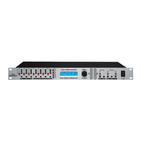
DIGISYNTHETIC DS2012 User manual

DS2012
FEEDBACK EXTERMINATOR
USER’S MANUAL
CLIP 12345678 10 12119
CHANN EL A
CHANN EL B
FILTER MODEBYPASS
NOISE GATE
RESET( ) SETTING( )
-38 12 624 --- SENSITIVITY

Contents
1. Front Panel Introduction ............................................................................................................................................................. 2
2. Rear Panel Introduction.............................................................................................................................................................. 2
3. System Connection Diagram...................................................................................................................................................... 3
4. Product Features........................................................................................................................................................................ 3
5. Function...................................................................................................................................................................................... 4
5.1. Power on........................................................................................................................................................................... 4
5.2. Level Display Function...................................................................................................................................................... 4
5.3. Notch Filters Status Display Functions .......................................................................................................................... 4
5.4. Bypass Mode Function ..................................................................................................................................................... 4
5.5. Reset Notch Filter Function .............................................................................................................................................. 4
5.6. Sensitivity Adjustment....................................................................................................................................................... 4
5.7. Mode Setting Function ...................................................................................................................................................... 4
5.8. Noise Gate Function ......................................................................................................................................................... 4
5.9. Limiter Function ................................................................................................................................................................ 4
5.10. High / Low Pass Filter Function ...................................................................................................................................... 5
5.11. Channels Connection Function ....................................................................................................................................... 5
5.12. Version Display Function ................................................................................................................................................ 5
5.13. Factory Reset Function ................................................................................................................................................... 5
6. Signal Flow Graph……………………………………………………………………………………………………………………………. 6
7. Specifications ............................................................................................................................................................................... 6
8. General troubleshooting Guidelines ............................................................................................................................................ 7
9. Accessories .................................................................................................................................................................................. 7

1
IMPORTANT SAFETY INSTRUCTION
Please read the basic protective measure as below
before using:
1. Please read all the safety instruction before using
the product.
2. This product must be earthed. If it should be
malfunction or break down, grounding provides a
path of least resistance for electric current to
reduce risk of electric shock.
3. This product is equipped with a cord having an
equipment-grounding conductor and a grounding
plug. The plug must be plugged into an appropriate
outlet that is properly installed and earthed in
accordance with all local codes and ordinance.
Danger: Improper connection of the
equipment-grounding conductor can result in a risk
of electric shock. Check with a qualified electrician
or serviceman if you are in doubt as to whether the
product is properly grounded. Do not modify the Plug
provided with the product-if it will not fit the outlet,
have a proper outlet installed by a qualified
electrician.
4. To reduce the risk of injury, close supervision is
necessary when the product is used near children.
5. Do not use this product near water-for example,
near a bathtub, washbowl, kitchen sink, in wet
basement or near a swimming pool or the lake.
6. This product may be capable of producing sound
levels that cloud cause permanent hearing loss. Do
not operate for a long period of time at high volume
level or at a level that is uncomfortable. If you
experience any hearing loss or ringing in the ears,
you should consult an audiologist.
7. This product should be located so that its location
or position does not interfere with its proper
ventilation.
8. This product should be located away from heat
sources such as radiators, heat registers or other
products that produce heat.
9. The product should be connected to a power supply
only of the type described on the operation
instructions or as marked on the product.
10. This product may be equipped with a polarized line
plug (one blade wider than the other). This is a
safety feature. If you are unable to insert the plug
into the outlet, contact an electrician to replace
your obsolete outlet. Do not defeat the safety
purpose of the plug.
11. The power-supply cord of the product should be
unplugged from the outlet when left unused for a
long period of time.
When unplugging the power-supply cord, do not pull
on the cord, but grasp it by the plug.
12. Care should be taken so that object do not fall and
liquid are not spilled into the enclosure through
opening.
13. The product should be serviced by qualified service
personnel when:
A. The power-supply cord or the plug has been
damaged;
B. Objects have been fallen, or liquid has been
spilled into the product;
C. The product has been exposed to rain;
D. The product does not appear to operate normally
or exhibits a marked change in performance;
E. The product has been dropped or the enclosure
damaged.
14. Do not attempt to service the product beyond that
described in the user-maintenance instructions.
All other servicing should be referred to qualified
service personnel.
15. WARNING: Do not place objects on the product’s
power cord or place it in a position where anyone
could trip over, walk on or roll anything over it. Do
not allow the product to rest on or to be installed
over power cords of any type. Improper installations
of this type create the possibility of fire hazard
and/or personal injury.
16. The power-supply cord should be unplugged from
the outlet when the products is completely power off
from the electric power sources and electric
networks.
CAUTION
RISK OF ELECTRIC SHOCK
DO NOT OPEN
CAUTION: TO REDUCE THE RISK OF ELECTRIC
SHOCK, DO NOT REMOVE COVER (OR BACK).
NOUSER-SERVICEABLE PARTS INSIDE. REFER
SERVICING TO QUALIFIED PERSONNEL
The lightning flash with arrowhead symbol
within an equilateral triangle is intended to
alert the user to the presence of
uninsulated dangerous voltage within the
product’s enclosure that may be of
sufficient magnitude to constitute a risk of
electric shock to persons.
The exclamation point within an
equilateral triangle is intended to alert the
user to the presence of important
operating and maintenance (servicing)
instructions in the literature
accompanying the product.
Applies only to altitudes below 2000m
areasafety
Applies only in Non-tropical area safety.
≤2000m

2
1. Front Panel Introduction
① Channel A Functions LEDs and Buttons
②Channel B Functions LEDs and Buttons
③ Input Level Meter
④ Bypass, second function Reset Filters
⑤ Filter Sensitivity and + /-
⑥Filter Modes Selection
⑦Noise Gate, Three Preset Switch
⑧Notch filters LEDs
2. Rear Panel Introduction
①Power Socket and Power Switch
②Firmware Update Interface
③Channel BXLR Output Socket
④Channel B 1/4" TRS Output Socket
⑤Channel B 1/4" TRS Input Socket
⑥Channel B XLR Input Socket
⑦Channel B Input Sensitivity Switch ,+4dBu/-10dBV
⑧Channel AXLR Output Socket
⑨Channel A1/4" TRS Output Socket
⑩Channel A 1/4" TRS Input Socket
⑪Channel A XLR Input Socket
⑫Channel A Input Sensitivity Switch ,+4dBu/-10dBV
CLIP
12345678 10 12119
CHANNEL A
CHANNEL B
FILTER M ODEBYPASS NOI SE GAT E
RESE T( ) SE T T I NG( )
-
38 12 624
---
SENSITIVITY

3
3. System Connection Diagram
4. Product Features
1. 56-bit Quad-Core DSP technology, high performance
AD/DA,48kHz Sampling Rate professional Dual Channel
Digital Feedback Eliminator.
2. 12 Notch Filters in each channel. Capture noise signal
automatically and intelligently processing.
3. Feedback suppressing sensitivity 3 Levels adjustable.
Static/Dynamic Notch Filters quantities freely allocated.
Adaptable to different environments.
4. High precision Noise Gate function, Threshold,
Algorithm start-up time and Release time adjustable.
5. Output with Limiter function, Limit the maximum output Level,
protect sound amplifying system effectively.
6. High and Low pass filter. Filter the outside noise effectively
according to different environments.
7. Designed with LEDs indicators on the panel, Display Input
level, Notch Filters status.
8. A key Bypass and Reset function, easy to install and test.
9. Friendly graphic GUI, easy and convenient to control all
functions and monitor all working status.
10. Program Management functions, Built-in 10 Preset storage
space, Data is saved automatically.
11. Program import and export function, avoid repeated
debugging.
Firmware Update or Online Interface
Online Cable

4
5. Functions
5.1. Power On
After Power on, Loading the parameters setup and static Filters
parameter last Shutdown time. Filters LEDs lit up.
5.2. Level Display Function
Panel is divided into upper and lower portions, correspond to A/B two
Channels. 5 Section Level indicator LEDs. Colors and Level definition
as below:
5.3. Notch Filters Status Display Functions
Right 12 LEDs correspond to 12 notch filters. If not light, notch filter
doesn’t work; Long light means static notch filter; Flicker means
dynamic notch filter.
5.4. Bypass Mode Function
Press button 【Bypass】,LED lit and indicates the current is under
Bypass status.
This operation will not affect the previous notch filters setting. Under
Bypass mode, all notch filters are not involved, but detect and record
howling frequency.
5.5. Reset Notch Filter Function
Reset function is used for Reset all notch filter in this channel. Press
button 【Bypass/Reset】and stay for 3 seconds, all notch filter Reset
and back to initial state, that means there are no filters at any frequency.
This operation will not change static/dynamic filters allocation.
After Reset onset, the LEDs light up from the first one until all, and then
all LEDs are off.
This feature is used to reset the static notch filter parameters have been
captured and re-capture environmental Noise points.
Besides, when the operation environment changed, and makes the
debugging work more convenient and efficient.
5.6. Sensitivity Adjustment
Each time press 【FB Suppression】, switch one level Sensibility
circularly, totally three levels(High, Middle, Low).
Different colors indicate different sensibility grades. Green represent
Low, Yellow represent Middle and Red represent High.
5.7. Mode Setting Function
Long Press 【Filter Mode】above 3 seconds, and dispose the quantities
of static and dynamic notch filter. Use buttons +/- to control increasing
and decreasing. Long light indicates static filter, flicker indicates
dynamic filter. Press again【Filter Mode】to finish notch filter
configuration. Back to normal working condition automatically.
5.8. Noise Gate Function
Noise Gate function is used to limit a certain level of noise or sound. For
example, it could be used to eliminate the noise of page turning from
attendees in the Conference system.
Long press button【Noise Gate】switch to use or disable Noise Gate
function. There are four levels as below:
Level OFF 1 2 3
Colour Lights off Green Yellow Red
Level Thresold - -70dB -60dB -50dB
Attack Time - 200ms 150ms 100ms
Release Time - 20ms 15ms 10ms
5.9. Limiter Function
Limiter function could prevent the Loudspeakers from burning when
output level unrestricted increased effectively.
It is also used in normal circumstances to limit the output level.
The device panel couldn’t set up the Limiter parameters. Only GUI
could adjust this. Parameters as below:
Limit Threshold -40dB~0dB
Attack Time 0.1ms~100ms
Release Time 0.010s~5s
Ratio 1:1~128:1
CLIP-38 12 624 ---
Green YellowGreen Green Red
Green YellowGreen Green Red
12345678 10 12119
FILT ER M ODEBYPASS NOI SE G AT E
RE SE T( ) SE T T I NG( )
SENSITIVITY
FILTER M ODEBYPASS NOI SE GAT E
RE SE T( ) SETTING( )
SENSITIVITY
FILT ER M ODEBYPASS NOI SE G AT E
RE SE T( ) SET T I NG( )
SENSITIVITY

5
5.10. High/Low Pass Filter Function
High/Low Pass Filter function is used for the applications which has not
high demand on bandwidth, such as Conference System. Voice
frequency band is around 80Hz-16 kHz. Limit or expect the voice band
into the system and remove the irrelevant outside voice. The howling
could be reduced in a certain degree.
Device Panel couldn’t set High/Low Pass filter. GUI could adjust. The
parameter is as below:
High Pass Filter OFF,19.7Hz~1kHz
Low Pass Filter OFF,5.99kHz~20.2kHz
Roll-off 12dB/Oct
5.11. Channels Connection Function
Channels connection is used to set A/B two channels parameters at the
same time. This could reduce repeat set and make it much more
convenient for users.
Press the two buttons 【Filter Mode】for CHANNEL A and CHANNEL B
simultaneously, A/B two Channels switch to connect mode or
disconnect mode. After connection, adjust any of Channels parameters,
another channel parameter will be also changed. When connecting, A/B
two Channels Filter Mode LEDs will be lit up together. When not links,
Two LEDs will be off.
5.12. Version Display Function
After Startup, long press two key combinations: CHANNEL A【FB
Suppression】& CHANNEL A 【Filter Mode】for 3 Seconds, all LEDs lit
up. After that, press CHANNEL A【Filter Mode】,all LEDs lights off, press
again CHANNEL A 【Filter Mode】
Now the version information as below(Number of LEDs light indicate the
version No.):
Left LEDs CHANNEL A Level display major version No. (eg. “1”in
“V1.0.2”)
Right CHANNEL A Filter LEDs display minor version No. (eg. “0"in
"V1.0.2”)
Right CHANNEL B Filter LEDs display minor version No. Low (eg. “2"in
"V1.0.2”)
Now press CHANNEL A【Filter Mode】to exit the version display.
5.13. Factory Reset Function
After Startup, long press three key combinations:CHANNEL A/B
【Noise Gate】and CHANNEL A 【Filter Mode】for 3 Seconds, all LEDs
lights off. Then press any of buttons on the panel, the device sun
properly. All parameters resume to default setting.
FILTE R M ODEBYPASS
NOI SE GAT E
RE SE T
( ) SE T T I NG
( )
SENSITIVITY
FILT ER MODEBYPASS
NOI SE GAT E
RE SE T( ) SETTING( )
SENSITIVITY
FILTER MODEBYP ASS NOI S E GAT E
RE SE T( ) SE T T I NG( )
SENSITIVITY
Green

6
6. Signal Flow Graph
7. Specifications
Input Channels Number 2 Channels,(XLR two,1/4”TRS two)
Output Channels Number 2 Channels,(XLR two,1/4”TRS two)
Input Impedance Unbalanced 10 kΩ/ balanced 20 kΩ
Output Impedance 150 Ω
Max. Input Level 14 dBu
Max. Output Level 14 dBu
Sampling Frequency 48 kHz
Gain 0 dB(+4dBu Position),12dB(-10dBVPosition)
Suppression Time 0.3 S @1 kHz
Sound Transmission Gain 9 dB
Dynamic Range 110 dB,A-Weighted
Frequency Response 20 Hz – 20 kHz,±0.5 dB
CMRR ≥70 dB
Crosstalk ≤-100 dB
Distortion + Noise ≤0.0017%(@1 kHz, +4dBu)
SNR 100 dB,A-Weighted,Reference+4dBu
Mains Input 100V-240Vac 50/60Hz
Power Consumption ≤12W
Fuse Size T1AL/250VAC
Net Weight 2.0kg
Dimensions(H×W×D)482×158×45(mm)
Noise Gate LevelMeter High/Low pass Filter
Input A Output A
Limiter
Input B
NotchFilter
Output B
Noise Gate LevelMeter High/Low pass Filter LimiterNotchFilter

7
8. General troubleshooting Guidelines
9. Accessories
Troubleshooting Resolution
No output and no
LEDs lit
1. Panel function buttons are workable and if LEDs lit.
2. Check POWER switch is on.
3. Check mains lead is connected.
4. Check the fuse hasn’t blown.
5. Please contact distributor if repeatedly reboot without result.
LEDs lit but no
Output
1. Check Input signal.
2. Check Output signal to Amplifier and Loudspeaker.
3. Power off and reboot.
4. Please contact distributor if repeatedly reboot without result.
Power and All LEDs
flickers
1. Reboot the device.
2. Please contact distributor if repeatedly reboot without result.
Online Failure
on the Computer
1. Check if the communication line is properly connected(Use the line with the device).
2. Check if the communication line driver installed correctly, the Device Manager in the PC could
recognize Virtual Serial Port(COM) No ? or !.
3. Close GUI, reconnect USB cable and click GUI to online.
4. Please contact distributor if repeatedly reboot without result.
Impossible to
suppress howling
1. Check if on Bypass state.
2. Check if the suppression sensitive is proper.
3. Check if the system Gain is too large.
4. Please contact distributor if repeatedly reboot without result.
Accessories Qty.
User’s Manual 1 Piece
USB to S Terminal Wire(Firmware Update or
Online use) Optional
Table of contents
Other DIGISYNTHETIC Computer Hardware manuals
Popular Computer Hardware manuals by other brands
alphatronics
alphatronics PSTN-2-IP GPRS installation manual
Behringer
Behringer MINIFEX FEX800 Technical specifications
Infineon
Infineon CY8CKIT-028-SENSE quick start guide
ViewCast
ViewCast OSPREY 240E user guide
Desin Instruments
Desin Instruments HS-7000 Series General instructions
Quest Engineering
Quest Engineering SUPER ELF manual
