Digital-Ally DVM-800 User manual
860-00186-00 Rev J
DVM-800
Operation Guide
Professional Vehicle Digital Video System
Copyright © 2013-2016, Digital Ally, Inc. All Rights Reserved. This publication may not be reproduced, stored in a retrieval
system, or transmitted in whole or part in any form or by any means electronic, mechanical, recording, photocopying, or in
any other manner without the prior written approval of Digital Ally, Inc.

860-00186-00 Rev J
Digital Ally Inc.| Introduction to the DVM-800 System
1-1
Table of Contents
Section - 1: Introduction to the DVM-800 System ..............................................................................................1-3
1.1 Overview of Features................................................................................................................................................................. 1-3
1.2 DVM Features Diagram............................................................................................................................................................. 1-4
Section - 2: DVM Configuration Overview .............................................................................................................2-1
Section - 3: Device Configuration .............................................................................................................................3-1
3.1 Default Configuration................................................................................................................................................................ 3-1
3.2 Using VuVault to Configure your DVM-800 ..................................................................................................................... 3-1
3.3 General............................................................................................................................................................................................. 3-3
Location .......................................................................................................................................................................................................3-3
Display..........................................................................................................................................................................................................3-4
Power ............................................................................................................................................................................................................3-5
Complete Vehicle Power Loss...............................................................................................................................................................3-6
Settings.........................................................................................................................................................................................................3-6
3.4 Profile............................................................................................................................................................................................... 3-7
3.5 Record .............................................................................................................................................................................................. 3-8
Recording Details .....................................................................................................................................................................................3-8
Cameras .................................................................................................................................................................................................... 3-11
3.6 Radar ............................................................................................................................................................................................. 3-12
3.7 Motion........................................................................................................................................................................................... 3-13
Accelerometer......................................................................................................................................................................................... 3-13
Vehicle Speed........................................................................................................................................................................................... 3-14
3.8 Sensor............................................................................................................................................................................................ 3-14
IF Box Input Sensors ............................................................................................................................................................................ 3-15
Input Sensor Device Detection, Threshold, and Wiring Guide ............................................................................................ 3-17
How to Configure a Backup Camera ............................................................................................................................................. 3-17
Reverse Record Override .................................................................................................................................................................... 3-18
Event Priority ......................................................................................................................................................................................... 3-18
Output Alarm.......................................................................................................................................................................................... 3-19
3.9 Data Transfer ............................................................................................................................................................................. 3-20
Network .................................................................................................................................................................................................... 3-20
USB.............................................................................................................................................................................................................. 3-21
3.10 GPS............................................................................................................................................................................................... 3-21
GPS Locations ......................................................................................................................................................................................... 3-21
Locations of Interest ............................................................................................................................................................................ 3-22
3.11 Activating your SD card within VuVault ...................................................................................................................... 3-23
Section - 4: DVM Operation ........................................................................................................................................4-1
4.1 Buttons for Operation ............................................................................................................................................................... 4-1
Function Keys...........................................................................................................................................................................................4-1
Navigation Buttons .................................................................................................................................................................................4-1
4.2 Display and On Screen Information.................................................................................................................................... 4-1
LCD Forced On Mode...............................................................................................................................................................................4-2
4.3 DVM Connectors.......................................................................................................................................................................... 4-2
USB Port.......................................................................................................................................................................................................4-2
External Microphone ..............................................................................................................................................................................4-2
Camera 1 Port............................................................................................................................................................................................4-2
Camera 2 Port............................................................................................................................................................................................4-2
Power Port ..................................................................................................................................................................................................4-2
4.4 Charging Information................................................................................................................................................................ 4-2
4.5 Memory Card Installation & Removal................................................................................................................................ 4-3
4.6 Powering On and Off.................................................................................................................................................................. 4-3
4.7 DVM Menu Functions ................................................................................................................................................................ 4-3
Viewing Current Configuration ..........................................................................................................................................................4-4
Logging into the DVM.............................................................................................................................................................................4-4

860-00186-00 Rev J
Digital Ally Inc.| Introduction to the DVM-800 System
1-2
Setting the Date and Time....................................................................................................................................................................4-4
Adjusting LCD Brightness .....................................................................................................................................................................4-5
Logging out of the DVM.........................................................................................................................................................................4-5
4.8 External Camera Control Buttons........................................................................................................................................ 4-6
4.9 Video Recording .......................................................................................................................................................................... 4-6
Start a Recording .....................................................................................................................................................................................4-6
Stop a Recording.......................................................................................................................................................................................4-7
Place Mark(s) in a Recording..............................................................................................................................................................4-7
Audio .............................................................................................................................................................................................................4-7
Muting the Audio......................................................................................................................................................................................4-7
4.10 Video Playback .......................................................................................................................................................................... 4-7
Slide View:...................................................................................................................................................................................................4-8
Playback Control:.....................................................................................................................................................................................4-8
4.11 Covert Operation ...................................................................................................................................................................... 4-8
4.12 Uploading Files into VuVault ............................................................................................................................................... 4-9
Option 1: SD Card.....................................................................................................................................................................................4-9
Option 2: Wi-Fi..........................................................................................................................................................................................4-9
4.13 Event Id Information Entry.................................................................................................................................................. 4-9
Section - 5: Wireless Microphone Operation .................................................................................................... 5-10
5.1 Syncing a Transmitter to a Charging Station................................................................................................................ 5-10
5.2 Basic Operation......................................................................................................................................................................... 5-10
5.3 Using the Microphone ............................................................................................................................................................ 5-10
5.4 Notification Alert Switch....................................................................................................................................................... 5-11
5.5 Out of Range ............................................................................................................................................................................... 5-11
5.6 Charging Information............................................................................................................................................................. 5-11
5.7 Status Indicators....................................................................................................................................................................... 5-12
5.8 Low Battery Warning ............................................................................................................................................................. 5-12
5.9 Remote Record Button........................................................................................................................................................... 5-12
5.10 Remote Accessory Control ................................................................................................................................................ 5-12
5.11 Muting the Wireless Microphone Audio ..................................................................................................................... 5-13
5.12 Muting the Audio for the In-Car Microphone ........................................................................................................... 5-13
Section - 6: Event Recording Management ...........................................................................................................6-1
6.1 Video Playback and Management ........................................................................................................................................ 6-1
Section - 7: Wireless File Transfer...........................................................................................................................7-1
Section - 8: Status Indicators .....................................................................................................................................8-1
Section - 9: Specifications ...........................................................................................................................................9-2
Section - 10: Support & Troubleshooting ............................................................................................................. 10-1
10.1 Firmware Updates ................................................................................................................................................................ 10-1
10.2 Firmware Update Instructions ........................................................................................................................................ 10-1
Manual Method...................................................................................................................................................................................... 10-1
Wireless Method .................................................................................................................................................................................... 10-2
10.3 External SD Card Maintenance........................................................................................................................................ 10-3
SD Card Requirements ........................................................................................................................................................................ 10-3
Formatting Requirements ................................................................................................................................................................. 10-3
10.4 Troubleshooting..................................................................................................................................................................... 10-3
10.5 DVM Error Messages............................................................................................................................................................ 10-5
10.6 Performing a Reset ............................................................................................................................................................... 10-5
10.7 Product Repair........................................................................................................................................................................ 10-5
10.8 Warranty Information......................................................................................................................................................... 10-6
10.9 FCC Notice................................................................................................................................................................................. 10-7
Section - 11: Contact Information............................................................................................................................ 11-1

860-00186-00 Rev J
Digital Ally Inc.| Introduction to the DVM-800 System
1-3
Section - 1: Introduction to the DVM-800 System
1.1 Overview of Features
DVM-800 Video System Features:
Two cameras built into the rear view mirror (One forward road facing, and one passenger facing
with IR illumination)
12XC external front facing variable zoom camera
Back seat camera
Optional backup camera available
Capable of recording full D1 (720x480, H.264) on two channels simultaneously
Integrated 3.5” color monitor – can be invisible when not in use
Wireless Microphone with 3000 foot range
Two in-car covert microphones
Recordings can be started by any of the following:
1. Automatically by the G-Force sensor (cornering, braking, and collision), GPS coordinates,
Vehicle Speed, IF Box sensors (sirens, lights, covert switch, etc.)
2. Manually by using the Record Button
3. Wireless Microphone
Recordings end:
1. When active input sensor trigger becomes inactive
2. Manually by using the Record Button
Pre-Event recording will capture up to 30 seconds prior to activating record. Pre-Event Record
time is adjustable in 6 second increments
Records metadata with the audio and video, including device serial number, vehicle speed, date,
time, sensors, radar, and GPS coordinates
Automated wireless 802.11(n) upload of video events to your configured back office server
Configuration and device update files can be wirelessly downloaded to each vehicle
Easy to use with minimal or no driver interaction required
Secure user login to the DVM
User may add traffic stop profile information at time of event
Integrated playback controls for in-vehicle viewing
LED and LCD status indicators
Configurable LCD monitor integrated behind the one-way rear-view mirror glass
Configurable LCD brightness for day and night modes
Compact interface box to allow more automatic record trigger options
Output Alarm that can turn on/off a device when an event recording begins
VuVault back office software available for organizing and viewing video event files, and advanced
device configuration
…and more!
860-00186-00 Rev J
Digital Ally Inc.| Introduction to the DVM-800 System
1-4
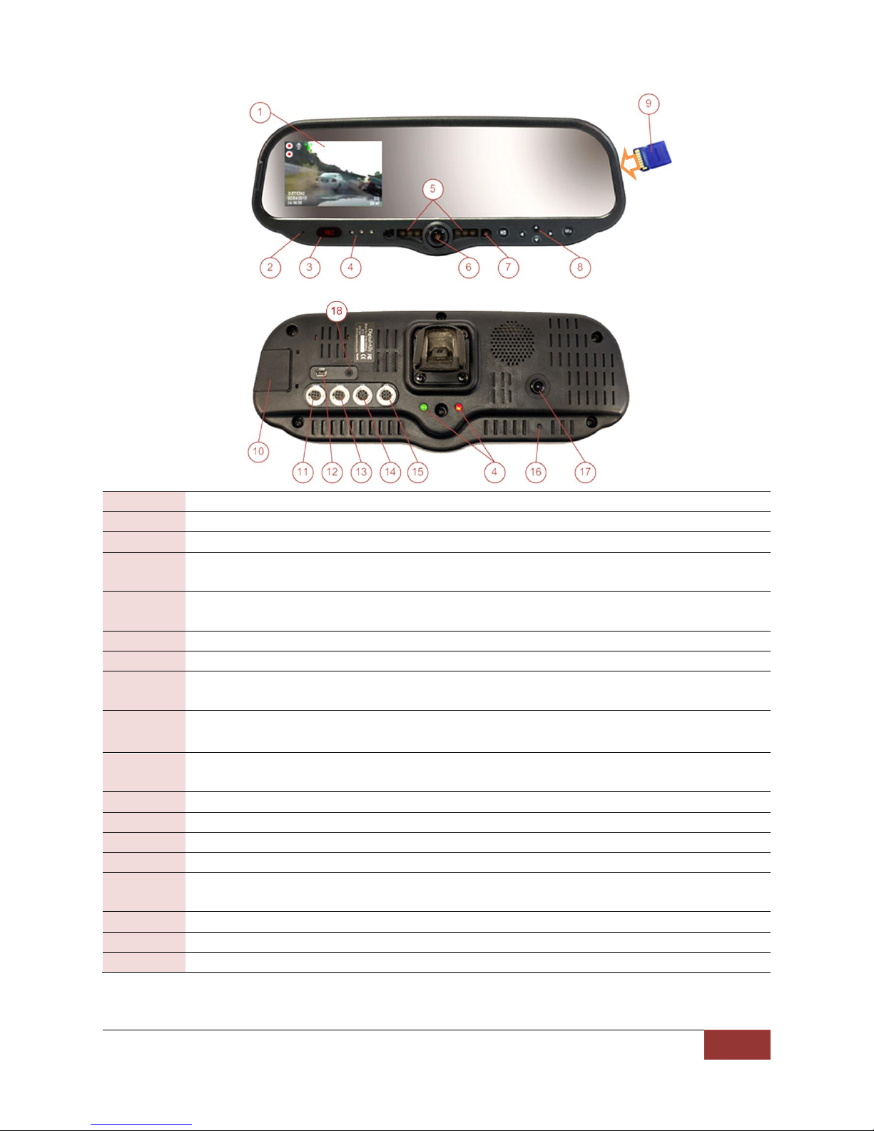
1.2 DVM Features Diagram
1
LCD Display: Used for viewing video
2
Internal microphone: Records audio from the passenger compartment
3
Manual Record button: This button is used to start/stop a manual event recording
4
LED Status Indicators (Passenger facing & Road facing): These visible indicators give the
operator feedback on the operational status of the DVM
5
Infrared Illuminators: Automatically provides Infrared illumination for the passenger
facing camera during low light conditions
6
Passenger facing camera: Records video of the vehicle passenger area
7
Ambient Light Sensor: Senses ambient light to automatically adjust LCD brightness
8
Menu and Playback Buttons: Used to navigate the DVM menus, play back videos, and log
into the system
9
External SD Card: The external SD card is installed behind the external SD door. The SD
card is installed at a slight angle and positioned with the connector pads as shown above
10
External SD door: Provides access to the external SD card. The included security screw kit
can also be installed
11
External Camera 1 Port: An external camera can be connected to the DVM with this port
12
USB Port: For data transfer and Wi-Fi download module
13
External Camera 2 Port: A 2nd external camera can be connected here
14
External GPS Port: The supplied GPS antenna is connected here
15
Power port: This port is used to provide power to the DVM or can be used to attach the
optional Interface Box to the system
16
Reset Button: Used to perform a hard reset of the system
17
Integrated road facing camera: Records the view in front of the vehicle
18
External Audio Input: The DWM Wireless Microphone audio cable is connected here

860-00186-00 Rev J
Digital Ally Inc.| DVM Configuration Overview
2-1
Section - 2: DVM Configuration Overview
Many customizable features are available for the DVM-800. The file that is used to update the DVM
configuration is named “deviceconfig”. This file contains all of the necessary wireless settings,
operational settings, and user logins. Section 3 will guide you through the process of creating the
configuration file using the Settings tab within the VuVault™ back office software. You will then save
the file using the Media Card Admin Tab within VuVault™ (Refer to Section 3-11 for details).
Once the configuration file has been created within VuVault, use one of the following methods to
update the DVM:
The DVM must be initially be configured for wireless communication using the SD card method
before Wireless Updates can be utilized.
Using your External SD Card
a. Copy the “deviceconfig” file to a SD card.
b. Install the SD card into the external card slot of the DVM.
c. The DVM will reboot and load the settings from the new configuration file. The old
configuration settings will be overwritten and discarded.
Wireless Updates
a) Once the new configuration is saved in VuVault, go to “Media Card Admin” and click
“Save to Folder”. Navigate to the local hard drive folder to which you wish to save
the “deviceconfig” file.
b) Open the WTM-Lite™program and click the “Update Devices” button, then the
“Deploy Update Files” button. (See the VuVault Wireless Server Setup Guide for
details).
c) Navigate to the hard drive location for “deviceconfig”, click on the file then press
OK.
d) Select the device or devices to update and press “Done”.
e) When the DVM reconnects to the FTP server, it will use settings from the new
configuration file. The old configuration settings will be overwritten and discarded.
If the Recording Mode of the DVM is set to ECA (Evidence Capture Assurance), the DVM will
not make any attempts to wirelessly connect to the FTP server unless there is at least one
Event Recording present on the DVM to be uploaded. In this case, you may make a quick
recording on the DVM to enable WiFi to connect. This will allow a new configuration or
firmware file to transfer from the server to the DVM.
Once the update process has started:
Do not remove power
Do not turn the ignition off
Do not remove the external SD card

860-00186-00 Rev J
Digital Ally Inc.| Device Configuration
3-1
Section - 3: Device Configuration
The DVM-800 is shipped with a default configuration so it can be used immediately after installation.
However, many parameters can be configured and saved as an activation file. The activation file is saved
to a local hard drive or external SD card. The DVM-800 is activated and configured using Digital Ally’s
VuVault™ back-office software. Use the VuVault Installation Guide to install the VuVault software. Once
installed, follow the instructions in this section to configure and activate your DVM.
ONCE THE DESIRED SETTINGS HAVE BEEN ENTERED, CLICK AND PROCEED TO SECTION 3.11
TO ACTIVATE YOUR SD CARD.
3.1 Default Configuration
If the unit has never been activated, it will use the following default settings preset from the
factory.
User Name/Password login entry
English language
Central Standard Time
Date format: mm/dd/yy
Time format: 12 hour time
Daylight saving time (DST) enabled
STANDBY mode, 30 second pre-event recording turned on.
External triggers: emergency lights and wireless microphone
Audio is off for pre-event, audio is on during event
60 second entry timeout
Recording resolution is D1 (720x480) @ 30 frames per second
Single Channel Recording
Record Mode is ECA (Evidence Capture Assurance)
All profiling screens disabled
Accelerometer disabled
30 minute ignition timer
Record external front road facing camera and internal passenger facing camera at 30fps
resolution
3.2 Using VuVault to Configure your DVM-800
VuVault is used to manage DVM-800 settings as well as activate a
DVM device or an external memory card for use in a DVM-800.
Before you can configure your device for use within VuVault, the
DVM serial number must be added into the system. Add your
device into VuVault by selecting Admin > Devices > Advanced >
Add Device. Type in your device serial number and assign it a name
within the system (the serial number is located on the back of the
DVM). When done, press Save (for more information consult the
VuVault Administrator Guide “Adding Devices” section).

860-00186-00 Rev J
Digital Ally Inc.| Device Configuration
3-2
Go to the Admin>Devices Tab. A separate configuration field will be available once a valid serial number
for the device has been added into the system. These settings will define how all users will interface
with the DVM (see below). Click on each sub-heading to reveal the available configuration options.
When done, press Save.
The button in the lower part of the main screen can be used to reset all configurations for
this device to the factory settings. This will not have any effect on the WTM Settings for wireless
connectivity located in the Data Transfer screen.

860-00186-00 Rev J
Digital Ally Inc.| Device Configuration
3-3
3.3 General
Location
Below are the configuration items for localization which are provided to address Date/Time settings and
display formats.
Local Time Zone
The local time zone is used to adjust the device when synchronizing to the Greenwich Mean
Time through the DVM-800 GPS antenna. Choose the time zone for your location.
Date Format
The date format displayed on the event recordings is selected through this setting.
Settings: mm/dd/yy [default]; yy/mm/dd; dd/mm/yy
Clock Source
Choose to receive the time setting automatically through the GPS signal or manually through the
DVM menu.
Settings: Manual, GPS [default]
Daylight Saving
Enable Daylight Saving setting and the time will be automatically adjusted for Daylight Saving
for the configured Local Time Zone. If this is disabled, time will not be adjusted for
Daylight Saving.
Settings: No, Yes [default]
Time Format
This time format allows the DVM-800 to be configured in a 12-hour format or a 24-hour format.
Settings: 24 Hour, 12 Hour [default]

860-00186-00 Rev J
Digital Ally Inc.| Device Configuration
3-4
Display
LCD Brightness
The LCD brightness is separately adjustable for day and night modes. To use this setting, choose
the desired brightness setting for day and night modes. A light sensor located on the front of the
DVM automatically places the system in the correct mode (day or night). This sensor uses a
sampling filter to sense changes in ambient light; therefore some delay will be present when
switching between the two modes. This is designed to prevent the DVM from switching
unnecessarily when the dome light or car door is opened, for example.
Settings: Day Mode 1-7 [Default =5]
Night Mode 1-7 [Default =5]
The LCD brightness setting can be temporarily overridden by the DVM operator. See page
5-5 for more information.
Record LED Behavior
The Red Record LED behavior is adjustable to accommodate your desired operation when the
DVM is in record mode.
Settings: Off (Stealth Mode), Slow, Medium, Fast, Solid [default]
LCD Mode
This parameter defines how the LCD screen will operate during pre-event and during recorded
events. Consult the table below.
Settings: Off, On, Auto [default]
Setting
LCD Behavior
ON
LCD will always be ON during pre-event & event recording.
User cannot turn off the LCD unless using covert mode.
OFF
LCD is ON as mirror boots-up to allow user login.
LCD is OFF during pre-event.
LCD is OFF during recorded events.
LCD can be forced to stay ON by holding the DOWN key for 3 seconds.
As soon as a recording completes, the LCD will remain ON for the duration of the Entry
Timeout as configured in VuVault to allow user input profiling screens (if profiling
screens are enabled).
AUTO
LCD is ON as mirror boots-up to allow user login.
LCD is OFF during pre-event.
LCD is ON during recorded events.
LCD can be forced to stay ON by holding the DOWN key for 3 seconds.
As soon as a recording completes, the LCD will remain ON for the duration of the Entry
Timeout as configured in VuVault to allow use of profiling screens (if profiling screens
are enabled).
Table 4-4: Choosing your LCD display behavior
This LCD behavior can be overridden for external sensors such as the light bar or reverse gear. LCD
overrides for connected external sensors are configured separately in the IF box input sensors section.

860-00186-00 Rev J
Digital Ally Inc.| Device Configuration
3-5
Power
The Power operation is configurable and specifies how the DVM will operate when the vehicle ignition
is turned to the ON or OFF positions. Two parameters control the power operation in order as follows:
Ignition Shutdown Timer
The Ignition Shutdown Timer specifies the amount of time the DVM remains fully powered when
the vehicle ignition goes from ON to OFF. If set to zero (0), the Ignition Shutdown Timer is not
used and the DVM will then follow the operation for the Days in LPS configuration.
Settings: 0 to 50 minutes, 1 hr, 2 hrs, 4 hrs, 8 hrs, 12 hrs, 24 hrs, and unlimited [default = 30 minutes]
During the Ignition Shutdown Time:
1. The DVM is fully powered and operational, including all high power consumption
devices, such as; cameras (including Pre-Event), recorded audio, GPS, IF Box, LCD
monitor, and the pre-event buffer.
2. The DVM will remain fully powered until the ignition shutdown timer expires. When the
timer expires, the DVM will then follow the operation for the Days in LPS configuration.
3. If the vehicle ignition switches on before the timer expires, the Ignition Shutdown Timer
is cancelled and will start over again when the ignition is turned off.
Days in LPS (Low Power Standby)
When the vehicle ignition goes from ON to OFF the DVM will first follow the operation for
Ignition Shutdown timer and then the operation for Days in LPS configuration. The Days in LPS
configuration specifies the number of consecutive days the DVM will remain in Low Power
Standby before completely powering off.
Settings: 0 to 10 days [default = 0 days]
Using a low power standby configuration ensures the DVM is fully powered on and ready to
record within a few seconds of the vehicle ignition switching on. During LPS:
1. All high power consumption devices will be turned off, such as; cameras (including Pre-
Event), GPS, LCD monitor, ECA recording, and the pre-event buffer. If configured,
Accelerometer, External Triggers, and the Manual Record button events will trigger an
event record. All other triggers are unavailable during low power standby.
2. The DVM will remain in low power standby until the number of days expires. When the
number of days expires, the DVM will completely power off.
3. If the vehicle ignition switches to the ON position before the number of days in low
power standby expires, the DVM will wake up to the full power state and be ready to
record within a few seconds.
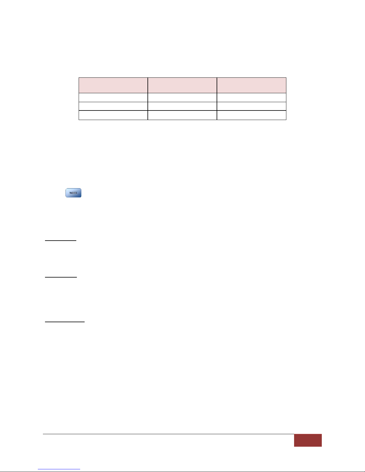
The DVM will draw a maximum of 170mA of current during Low Power Standby. Typically, a new
or strong vehicle battery will provide enough current to power the DVM in Low Power Standby
for 5 days without discharging the battery. The vehicle’s battery current rating, battery age, and
other equipment that remains powered on when the vehicle ignition is off will affect the
maximum consecutive days the DVM should remain in Low Power Standby. The following table
When in LPS, “Sensor Only” type IF Box sensors will not turn on the LCD.
860-00186-00 Rev J
Digital Ally Inc.| Device Configuration
3-6
can be used as a general guideline for determining the Days in LPS setting; actual results may
vary:
Battery C20 Rating
(Ah)
No Additional or Minimal
Load (days)
Additional Load
(days)
45
6 – 8
3 -5
80
10
7-10
100 and greater
10
10
Complete Vehicle Power Loss
During an event record, if vehicle power is completely lost to the DVM system, the DVM will
switch to the internal battery to end the event record, close any open files to prevent data
corruption, and then power off after 60 seconds. If the DVM is not recording when vehicle
power is completely lost, the DVM will power down after 60 seconds using the internal backup
battery.
External cameras on the DVM-800 rely on the vehicle power supply. Thus, during a complete
vehicle power loss to the DVM system, no video can be captured from the external cameras.
Settings
Audio Mute
Choose whether to allow or not allow the DVM user to mute the audio while the DVM is
recording.
Settings: Disabled, Enabled [default]
Login Mode
Choose how the user will log into the DVM system. User device logins are configured in the
VuVault Admin>Users tab. Users may log in using their User Name or Device sign on ID. If set to
none, no DVM login will be required (not recommended).
Settings: None, User ID; User Name [default]
Entry Timeout
Enter the number of seconds when LCD menu items timeout from no user input. This timer
applies to the Main Menu and Profile screens. When the timer has expired, the DVM will return
to standby mode.
Settings: 0 to 600 seconds [default = 60 seconds]
Table 4-6: Number of days a vehicle can remain in
Low Power Standby before draining a vehicle battery.

860-00186-00 Rev J
Digital Ally Inc.| Device Configuration
3-7
3.4 Profile
Choose whether the DVM user, at the end of each recorded event, will be prompted to choose from the
following list of criteria. Profile entries will become part of the event metadata. The menu will be
displayed until the user enters relevant data or the Entry Timeout expires.
Event Id Enable
Event ID’s are defined by an administrator in VuVault™ back office software. To configure this
parameter, go to the Admin > Events tab. If enabled, the DVM user will be prompted to choose
from a list of defined events at the completion of a video recording. See the VuVault
Administrator Guide to learn how to create or edit events.
Settings: Enabled, Disabled [default]
Incident Enable
Incident ID parameters are predetermined and can be enabled or disabled.
Settings: Enabled, Disabled [default]
Ethnicity Profile
Ethnicity parameters are predetermined and can be enabled or disabled.
Settings: Enabled, Disabled [default]
Age Profile
Age parameters are predetermined and can be enabled or disabled.
Settings: Enabled, Disabled [default]
Gender Profile
Gender parameters are predetermined and can be enabled or disabled.
Settings: Enabled, Disabled [default]
Figure 3-7: DVM Device User prompts if Profile setting is “Enable”

860-00186-00 Rev J
Digital Ally Inc.| Device Configuration
3-8
3.5 Record
This section defines how the DVM will record audio and video events to the storage media.
Recording Details
Your DVM-800 includes an external 32GB SD card which is normally used as the primary memory
storage. Use the following options in this section to configure your record settings.
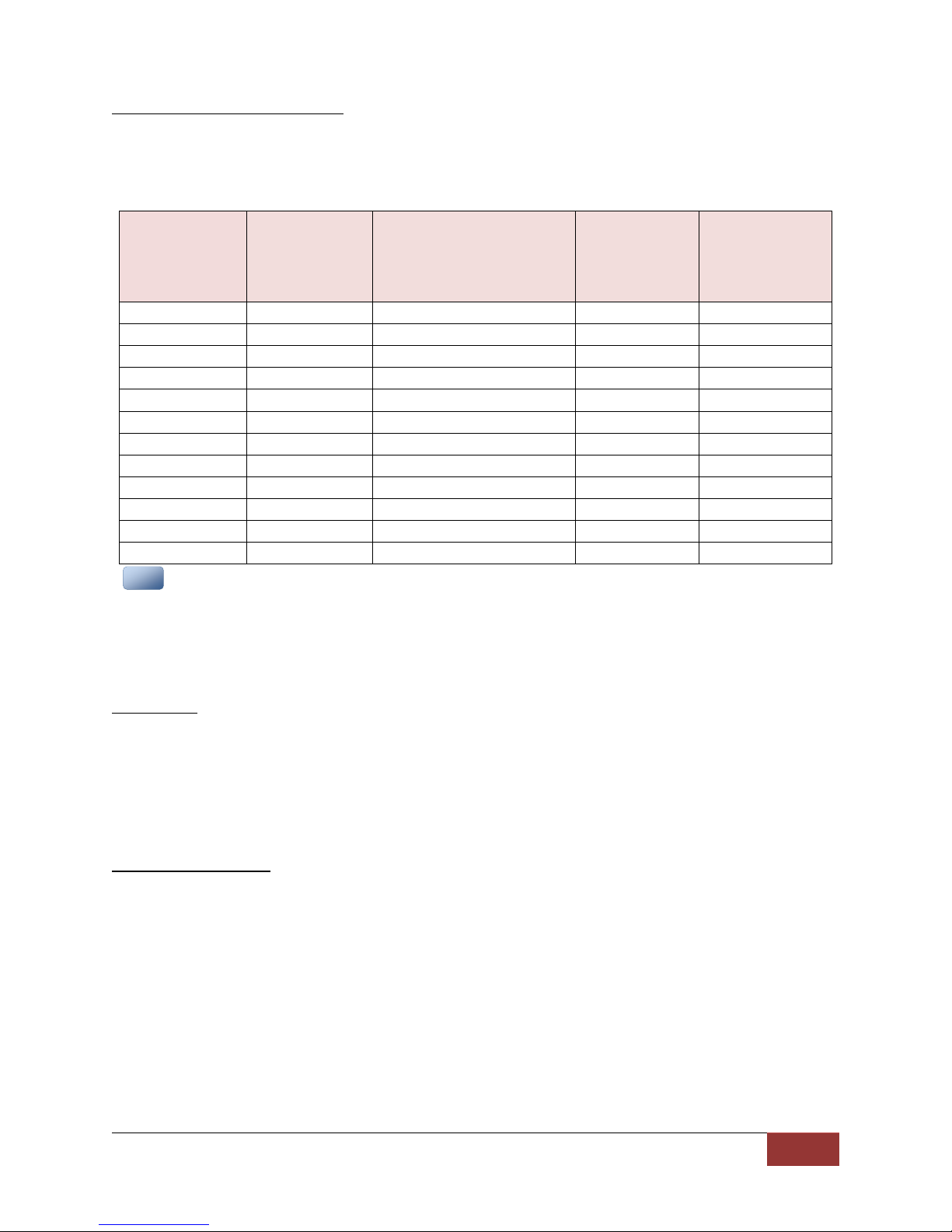
Record Quality
The Record Quality parameter allows the video compression bit rate to be adjusted. Digital video
is compressed by taking out data that remains constant from each frame, and only storing data
that actually changes. This allows the file size of videos with still backgrounds to be much smaller
than they would be if the background had to be present in every single frame. The bit rate is the
amount of bits that can be used in one second of video.
The higher the record quality, the higher the bit rate and the size of the event files. The default
setting is “very high” for maximum video quality, but can be lowered to “standard” or “high” to
increase the compression rate and reduce the required storage space (see figure 3-9).
Settings: Standard (512Kbps), High (1Mbps), and Very High (2Mbps) [default]
860-00186-00 Rev J
Digital Ally Inc.| Device Configuration
3-9
Record Frames Per Second (FPS)
Sets the number of frames per second the DVM will record. The higher the setting, the better
the video quality, and the larger the size of the event files (see figure 3-9).
Settings: 5FPS, 10FPS, 15FPS, 30FPS [default]
Record
Quality
Record Frames
Per Second
Storage Needed
(MB per Event Minute)
Available hours
of video using a
32GB SD card
(Single Channel
Recording)
Available hours of
video using a
32GB SD card
(Dual Channel
Recording)
Very High
30fps
30MB
15.8 hours
7.9 hours
Very High
15fps
17MB
29.2 hours
14.6 hours
Very High
10fps
12MB
40.4 hours
20.2 hours
Very High
5fps
7MB
70.2 hours
35.1 hours
High
30fps
16MB
31.0 hours
15.5 hours
High
15fps
9MB
54.6 hours
27.3 hours
High
10fps
7MB
70.8 hours
35.4 hours
High
5fps
5MB
98.2hours
49.1 hours
Standard
30fps
9MB
55.2 hours
27.6 hours
Standard
15fps
6MB
82.8 hours
41.4 hours
Standard
10fps
4MB
124.0 hours
62 hours
Standard
5fps
3MB
164.4 hours
82.2 hours
File size varies with the Record Quality, FPS settings, and video content. Consult the table above to
determine which settings are best for your application. The data above was extrapolated from 1 minute
video file samples, and were focused on a stationary background. The storage column represents both
channels of video combined together. This is intended as a general guideline and actual compressed video
size will vary based on subject matter.
Event Audio
The Event Audio setting determines how audio will be recorded to your DVM. If “Enabled”, audio
information is recorded both during the recorded event and during the configured pre-event
buffer time. If “Enabled (w/o Pre-Event)”, audio will be recorded during the event but not
recorded during pre-event. If “Disabled”, no audio will be recorded. If the Pre-Event Buffer Time
is set for 0, Pre-Event Audio is turned off.
Settings: Enabled, Disabled, Enabled (w/o Pre-Event) [default]
Pre-Event Buffer Time
This option allows you to set the amount of time for the pre-event buffer, in 6 second
increments. The DVM will buffer the last 6-30 seconds of video prior to the start of the recorded
event so it can be recorded as part of the event. A setting of “0 second” disables the pre-event
function and removes the pre-event audio setting from the Event Audio dropdown menu.
Settings: 6, 12, 18, 24, 30 seconds [default]
Figure 3-9: Estimating your storage requirements
N
NO
OT
TE
E

860-00186-00 Rev J
Digital Ally Inc.| Device Configuration
3-10
Record Mode
In addition to the external SD Card, the DVM-800 has 32GB of internal memory which is
permanently installed in the unit. Select one of the following three modes to determine how the
storage memory is utilized.
1. Internal
All triggered and manual recordings will be saved to the mirror’s Internal
Memory. These recordings will only be accessible by wireless upload to VuVault
or by using the USB cable to connect the DVM to a PC and uploading to VuVault.
In this mode, an external SD card does not need to be present in the DVM.
2. External
All triggered and manual recordings will be saved to the External SD Card. These
recordings will be accessible by wireless upload to VuVault or by manual transfer
by removing the external SD Card and using an SD Card reader with a PC.
3. ECA (Evidence Capture Assurance)
All triggered and manual recordings will be saved to the External SD Card as
above, but, the DVM will also continuously record from the default cameras
(Source 1 and Source 2 as configured in the Record tab) to the Internal memory.
ECA recording will be temporarily suspended during any of the following:
A triggered or manual event is recording.
When the DVM is wirelessly transferring files.
The video playback screen is on or video is being played on the DVR.
ECA will always record in “Loop” mode: When the internal memory is completely
filled, the earliest recording will always be deleted to free up memory for new
recordings.
Settings: Internal, External, ECA [default]
Retrieving ECA Recordings from Internal Memory
Using the supplied USB cable, connect a PC to the USB/WiFi Port on the back of
the DVM and restart the system. Recordings can be selected and uploaded to
VuVault using the Upload feature. Alternatively, the files can be copied to the PC
using Windows Explorer.
If the decision is ever made to switch from ECA mode to Internal Memory mode after having already
used ECA, be sure to upload or manually delete the existing ECA recordings from the internal memory
via USB cable connection to a PC. Failure to do so will cause the DVM to wirelessly upload all of the
existing ECA recordings, which would take many hours to complete.
Event Loop
Use this setting to determine how the External SD Card memory is handled.
1. Select Off (Default setting) to allow the DVM to make triggered and manual recordings
only until the External SD Card is full. No further recording will be possible until existing
recordings are uploaded to VuVault or the full SD card is replaced.
2. Select On for the DVM to operate in “loop” mode. When the external SD Card memory
is full, the DVM will delete the earliest recording to free up memory for new recordings.
In this mode, the DVM will always be able to make new recordings, but will risk the
possible overwriting of an important recording if it has not been uploaded by the time
the SD card becomes full.
Settings: On, Off [default]
N
NO
OT
TE
E

860-00186-00 Rev J
Digital Ally Inc.| Device Configuration
3-11
Number of Channels
1. Select Dual to configure the DVM to record two camera sources simultaneously when a
recording starts. Both record status icons on the DVM display will be activated when
recording.
2. Select Single for triggered and manual recordings to initially record from only one
camera (Indicated by the upper record status icon on the DVM display). The second
channel recording can then be manually started by pressing the Play/Stop button on the
DVM (Channel 2 recording is indicated by the lower record status icon).
Settings: Single, Dual [default]
Pressing the REC button while 2 channels are recording will stop both channel recordings.
Cameras
The DVM contains two internal cameras and also supports two external cameras. The DVM can record
two video sources simultaneously. You may choose one of the four camera inputs to assign to each
source. The selection you make here will become the default camera selections for all recorded events.
IF Box Input Sensors and the optional backup camera may have their own separate camera
configuration if desired. Consult section 3.8 to review your IF box input sensor configuration.
Source 1
This is the main video channel available for display on the LCD during a recorded event,
and is typically reserved for the 12XC external front facing camera attached to the
External #1 (CAM 1) port on the back of the DVM. Choose one of four available camera
inputs for this source.
Settings: Internal Passenger, Internal Road Facing, External #2, External #1 [default]
Source 2
This is the secondary video channel and is not displayed on the LCD during the recorded
event. If a backup camera is not utilized, choose External #2 to record the external back
seat camera attached to the CAM 2 port on the back of the DVM. If a backup camera is
utilized, choose either the Internal Passenger or Internal Road Facing camera so that the
backup camera image will be switched correctly. Choose one of the three remaining
camera inputs for this source. For more information on backup camera configuration,
see how to configure a backup camera.
Settings: Internal Passenger, Internal Road Facing, External #1, External #2 [default]
IR LED
Choose whether to enable the infrared LED’s on the DVM front panel to aid in the illumination of
the internal passenger facing camera. If set to AUTO, an ambient light sensor located on the
front of the DVM automatically turns on the IR LED’s during low light conditions. Choose OFF to
disable the IR LED’s.
Settings: Off, Auto [default]
N
NO
OT
TE
E
860-00186-00 Rev J
Digital Ally Inc.| Device Configuration
3-12
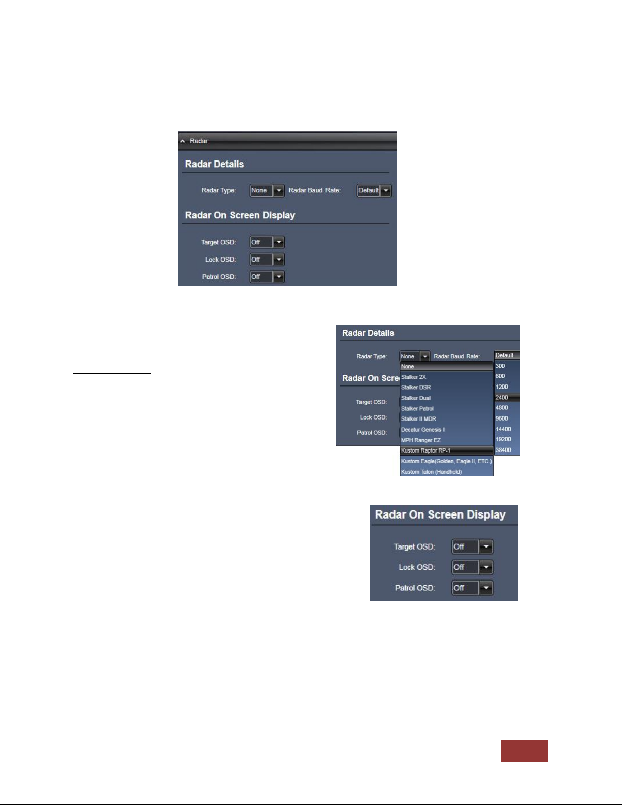
3.6 Radar
The DVM-800 has the ability to display and record radar information in a video recording. Use the
Radar section to configure the settings for the specific type of radar that is used.
Radar Type
Select the model of the radar being used.
Radar Baud Rate
Select the Baud Rate of the radar being used.
Radar On Screen Display
Select what you want to have displayed on the DVM.
860-00186-00 Rev J
Digital Ally Inc.| Device Configuration
3-13
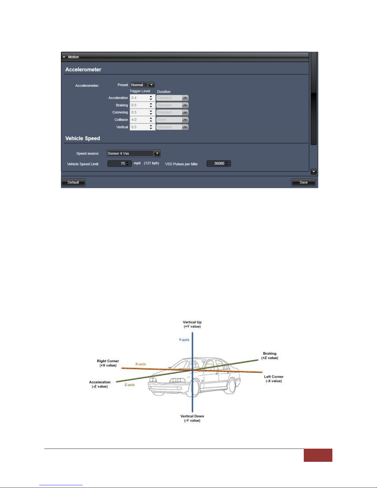
3.7 Motion
Accelerometer
The DVM-800 has a built-in accelerometer which can be used to trigger an Event Record when the set
G-Force levels are exceeded. The accelerometer can be used to activate an event recording based on
the independent G-force levels for acceleration, braking, cornering, collision, and vertical movements.
Accelerometer event triggers can be disabled by setting the G-force levels to zero (0) in the
configuration of the DVM. Setting the G-force level greater than zero (0) will set the event trigger
threshold. When the event trigger threshold is met or exceeded, an event trigger will occur and the
DVM will begin an event record. The accelerometer duration parameters determine the amount of time
the G-Force level must be present before triggering an event.
Settings: Low, Normal, High, Disabled [default], Custom
Figure 4-11: Accelerometer axis orientation for the DVM-800.

860-00186-00 Rev J
Digital Ally Inc.| Device Configuration
3-14
Vehicle Speed
Speed Source
The vehicle speed can be used to trigger an event record. Vehicle speed can be calculated
through the use of the supplied GPS antenna, or by utilizing the Vehicle Speed Sensor (VSS)
signal. The Vehicle Speed Limit can then be adjusted to the speed at which an event record
should occur. Select None if an event record is not required when the vehicle exceeds the speed
limit.
Settings: None [default], Sensor 4 VSS, GPS
When Sensor 4 VSS is selected as the Speed Source, the Sensor #4 settings will automatically be
configured as an Event Trigger as shown in the IF Box Input Sensors screen below. The IF Box
Sensor 4 input wire must be connected to the Vehicle Speed Sensor output to utilize VSS.
When the Speed Source is set to None, no event trigger will occur when the Vehicle Speed Limit is
exceeded, however the vehicle speed is still calculated using GPS and is logged into the metadata
for all events that are recorded.
VSS Pulses per Mile
Input the number of VSS pulses that are generated during one mile of vehicle travel. This varies
by the make and model of the vehicle.
3.8 Sensor
The Interface Box (IF Box) is an external module that allows connection to vehicle sensors and triggers.
The IF Box provides the DVM system with the capability to add common event record triggers such as
emergency lights, reverse, vehicle speed sensor (VSS), brakes, or other sensors. In addition, the IF Box
provides connectivity from the vehicle power system to the mirror, communicates with the mirror using
a CAN bus interface, and provides external connection for extending the CAN bus to other Digital Ally
devices.
When adding a new DVM or IF Box, or when either is replaced, always perform a firmware update. The
firmware update will ensure that the IF Box has the correct version installed. Refer to Section 10 for
firmware update instructions.
Other manuals for DVM-800
2
Table of contents
Other Digital-Ally Car Video System manuals


Popular Car Video System manuals by other brands

Phonocar
Phonocar VM192 Mounting instructions

Boss Audio Systems
Boss Audio Systems BV-T5.0 user manual

XZENT
XZENT ARGO Series Mounting instruction

Kia
Kia Optima Hybrid Features & functions guide

Audiovox
Audiovox MMD7HRPKG - Movies2Go - DVD Player user guide

Stinger
Stinger HEIGH10 UN1810E-AU1 installation guide


