Digital-Ally DVM-500 User manual

Digital Ally DVM User Guide Rev. F (334/1.6.2)
DVM-500 User’s Guide
Digital In-Car Video System
Copyright © 2006-2008, Digital Ally, Inc. All Rights Reserved, Printed in U.S.A. This publication may not
be reproduced, stored in a retrieval system, or transmitted in whole or part in any form or by any means
electronic, mechanical, recording, photocopying, or in any other manner without the prior written approval
of Digital Ally, Inc.

DVM-500 User’s Guide Digital In-Car Video System
Digital Ally DVM User Guide Rev. F (334/1.6.2)
Table of Contents
DVM-500 SYSTEM – INITIAL SETUP............................................................................1
SYSTEM COMPONENTS..................................................................................................3
DIGITAL VIDEO MIRROR (DVM)............................................................3
WIRELESS MICROPHONE (RMT)............................................................5
Synching the Wireless Microphone (RMT) to the DVM.....................5
LED Indicators..................................................................................6
Charging the RMT in a vehicle..........................................................7
Charging the RMT on the desktop.....................................................7
MAIN CAMERA.......................................................................................8
OPERATING MODE ..........................................................................................................9
POWERING UP THE DVM .......................................................................9
LOGGING INTO THE DVM.......................................................................9
Select User.........................................................................................9
Enter User ID ....................................................................................9
Enter Password..................................................................................9
POWERING DOWN THE DVM .................................................................9
INTERNAL LCD MONITOR....................................................................10
Recording Space Available..............................................................10
Low Space Available Alerts .............................................................10
RECORDING.......................................................................................... 11
CAMERA CONTROLS.............................................................................12
How to Use Covert Mode ................................................................13
MENU MODE....................................................................................................................14
MAIN MENU.........................................................................................14
PLAYBACK MENU.................................................................................15
ASSIGN EVENT ID MENU .....................................................................16
VIEW EXTERNAL VIDEO.......................................................................16
CAMERA MENU....................................................................................16
CAMERA MENU....................................................................................17
MONITOR MENU...................................................................................19
BACKLIGHT MENU ...............................................................................19
SYNCH WIRELESS MICROPHONE MENU ...............................................20
DOWNLOAD VIA USB PORT .................................................................20
LOGOUT ...............................................................................................20
SETTINGS MENU ............................................................................................................21
DATE/TIME MENU................................................................................21
DISPLAY TEXT MENU ...........................................................................22
RECORD MODE MENU..........................................................................22
RECORD TRIGGERS MENU....................................................................23
INTERNAL MICROPHONE MENU............................................................24
WIRELESS MICROPHONE MENU ...........................................................25
RADAR INTERFACE MENU ....................................................................25
POWER CONTROL MENU ......................................................................26
SPEEDOMETER MENU...........................................................................28
USB MENU ..........................................................................................29
GPS CONFIGURATION...........................................................................29
ACCELEROMETER SENSOR MENU.........................................................30
FRONT CAMERA FOCUS........................................................................31

DVM-500 User’s Guide Digital In-Car Video System
Digital Ally DVM User Guide Rev. F (334/1.6.2)
RESET TO FACTORY DEFAULTS .............................................................31
TROUBLESHOOTING ....................................................................................................32
HOW TO RESET THE DVM-500 SYSTEM...............................................33
PROTECTING THE DVM-500 SYSTEM WHEN JUMP-STARTING...............33
PRODUCT REPAIR .................................................................................33
HOW TO UPGRADE/REFRESH THE DVM-500 SYSTEM SOFTWARE ........34
LIMITED WARRANTY ...................................................................................................35
CONTACT US....................................................................................................................36
APPENDIX A – DVM-500 INSTALLATION KIT............................................................1
APPENDIX B – DVM-500 SYSTEM SPECIFICATIONS...............................................1

DVM-500 User’s Guide Digital In-Car Video System
Digital Ally DVM User Guide Rev. F (334/1.6.2) Page 1of 36
DVM-500 System – Initial Setup
1. VideoManager should be installed and configured on a computer
running Windows XP SP2 before using the DVM for the first time.
Vehicles, Users, and Event IDs are defined during the initial setup of
VideoManager. Please refer to the VideoManager User’s Guide for
instructions.
2. The DVM’s CF card comes with 2 default login settings already
configured, and they are as follows:
User1 – Password = 22222
Admin – Password = 11111
3. The DVM has been shipped with a 4GB CF card already installed. The
memory card must be fully inserted before powering up the unit or a
message “initializing CF card” will appear on the screen and the unit will
fail to start up. Please note that the DVM requires high-speed memory
cards. SanDisk brand Ultra II and Extreme III cards are the only CF
cards approved for use in the DVM. A 4GB CF card will not be included
with DVM-500 systems that are ordered with an 8GB or 16GB CF card.
Important: Do not force the CF card into the slot. Doing so may
permanently damage the DVM. The card only goes in one way, with
the back side of the card towards the front of the DVM and the colorful
label side facing the back of the DVM. The memory card should slide in
easily with slight resistance as the card seats into the slot. If the card is
difficult to insert, pull it back out and make sure it is facing the right
direction and align it carefully with the slot as the card is reinserted. The
white label side should be facing towards the back of the vehicle, as
seen in the picture to the left.
Important: Do not insert or remove the CF card while the
DVM is powered on!
4. The main camera must be connected to the DVM using the included
cable. If it is not connected, the DVM will display the message “Power
down and connect camera” after logging in.
5. The wireless microphone (RMT) must be fully charged before using it
with the DVM. The RMT can be charged using the in-car charging cradle
or the desktop charging cradle. Two charging cradles are included in the
DVM-500 kit: one for vehicle use and one for desktop use.
Important: Charge the RMT for 12-16 hours before using it for
the first time. Failure to fully charge the RMT may result in
permanent loss of battery capacity. After an initial charge, the
RMT should fully recharge in approximately 4-5 hours.
(Steps continue on next page)

DVM-500 User’s Guide Digital In-Car Video System
Digital Ally DVM User Guide Rev. F (334/1.6.2) Page 2of 36
6. In order to use the wireless microphone (RMT), an antenna must be
attached to the DVM. The DVM ships with a small “rubber duck”
antenna attached to the left side.An external roof antenna is also
included to enable greater transmission range, if needed. Please note that
the rubber antenna must be removed in order to install the external roof
antenna onto the DVM. If using the external antenna, please mount it
forward of any light bar on the roof of the vehicle for a clear line-of-sight
to the RMT.
Important: When installing the external antenna, do NOT use a
wrench to tighten the cable to the mirror. This connection should only
be finger tight. Over tightening the connection can potentially cause
damage to the connector inside the DVM.
The RMT must be within three feet of the rubber or external
antenna during the synchronization process. Refer to the section
“Synching Wireless Microphone to the DVM” (page 5) for the procedure
on synchronizing the RMT to the DVM prior to recording videos.
7. Attach the GPS antenna to the rear of the DVM. This antenna can be
mounted on the dash or magnetically attached to the roof to receive GPS
signals. Signal reception can be verified by enabling the GPS display
text; please refer to Display Text Menu (page 21) for this option.
(End of initial setup steps)

DVM-500 User’s Guide Digital In-Car Video System
Digital Ally DVM User Guide Rev. F (334/1.6.2) Page 3of 36
System Components
Digital Video Mirror (DVM)

DVM-500 User’s Guide Digital In-Car Video System
Digital Ally DVM User Guide Rev. F (334/1.6.2) Page 4of 36
All recordings are stored on the Compact Flash (CF) card. Before the
DVM-500 system can be operated, an activated CF card must be
installed in the DVM.
Inserting or Removing the Compact Flash Card
The DVM has a special access door that must be opened with the
included key before the CF card can be accessed.
Important: Do not insert or remove the CF card while the unit is
powered on. Briefly press the MENU button before removing the
card and look for any activity on the LCD screen. The CF card may
be safely removed from the DVM if no activity is notice on the LCD
screen.
NOTE: This procedure may require two hands and should not be
attempted while driving the vehicle.
How to unlock and open the access door:
1. Align the end of the key with the slots and stud of key hole. The
key hole is located on the bottom of the unit, next to the metal CF
card access door.
2. Insert the key into the key hole (key should push in approximately
1/8”). Do not rotate or turn the key, it simply pushes into the
keyhole.
3. While keeping the key inserted into the keyhole, use the black
knob to slide open the door until it stops (approximately 1/4”).
4. Remove the key from the key hole and then slide the door open
the rest of the way to access the CF card.
Note: The white label on the back side of the CF card should be visible when
inserting the CF card into the DVM. Please refer to the picture on the left.
DVM-500 User’s Guide Digital In-Car Video System
Digital Ally DVM User Guide Rev. F (334/1.6.2) Page 5of 36
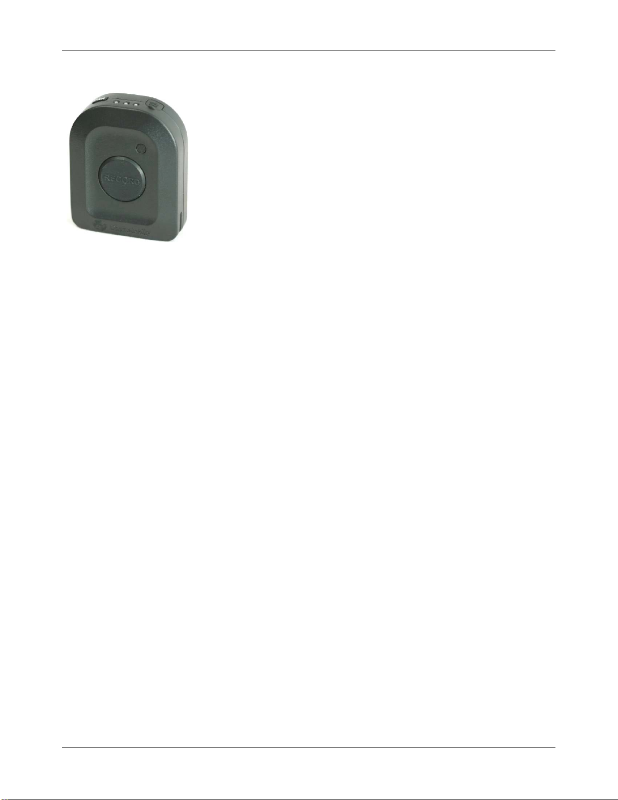
Wireless Microphone (RMT)
The Wireless Microphone (RMT) can be worn on a belt or other location.
The RMT contains a condenser mic built into the face of the unit. A lapel
mic can be attached to the input port located on the top of the RMT. The
RMT also features a large RECORD button that is used to remotely start
and stop a recording on the DVM.
Synching the Wireless Microphone (RMT) to the DVM
Prior to first use, the wireless microphone must be synchronized with
the Digital Video Mirror (DVM). Please note that the RMT must be
within 3 feet of the antenna during the synchronization process.
1. Select Synch Wireless Microphone from the Main Menu.
2. Select Wireless Mic #1 or #2
3. Remove the Wireless Mic from the charging cradle.
4. Hold down the Record button while turning it on until the Red,
Amber and Green LEDs begin to flash.
5. Press the MENU Button on the DVM to begin searching for the
Wireless Mic.
Repeat the above procedure for Wireless Mic #2 if synching a second
RMT to the same DVM.
Power On/Off
The PWR (power) button toggles the RMT ON and OFF. To power
ON, press and hold the PWR button (located on the top of the RMT)
until the Green LED starts blinking. The LED will begin flashing every
3 seconds to indicate that it is powered ON and in Standby Mode. To
power OFF the RMT, press and hold the PWR button until the Green
LED lights steady and then turns off.
Start TransmittingAudio (Recording)
Transmit mode is entered by pressing and holding the RECORD button
on the RMT for a few seconds while it is in standby mode (Green LED
flashes periodically). The Red LED will begin flashing at 4 times per
second as it searches for the DVM unit on a clear channel. Release the
RECORD button, and if communication is established with the DVM,
the Red LED will be on steady. If the RMT is unable to establish
communication with the DVM in approximately 4-6 seconds, then it
will return to standby mode.

DVM-500 User’s Guide Digital In-Car Video System
Digital Ally DVM User Guide Rev. F (334/1.6.2) Page 6of 36
LED Indicators
LED indicators are used to indicate the operational status of the RMT.
LEDs are laid out left to right from the PWR button as: Red, Amber,
Green.
While Operating
Red LED – On steady indicates that it is transmitting audio.
Amber LED - On steady if out of range while it is transmitting audio.
The Amber LED will flash slowly when battery has 25% charge left
and will flash rapidly at 15% remaining.
Green LED - Flashes every 3 seconds to indicate Power On Standby
mode.
Ready to Sync - All three LEDs flash quickly. Waiting for in car
transceiver to attempt sync.
During Sync - alternately flash Red and Green LEDs.
Sync Finished -All LEDs on steady for 1 second to indicate Sync
Finished, then unit will revert to Standby mode.
While Charging
Battery 25% charged -- 1 flash of the Amber LED
Battery 50% charged -- 2 flashes of the Amber LED
Battery 75% charged -- 3 flashes of the Amber LED
Battery 100% charged -- 4 flashes of the Amber LED
Important: The RMT is automatically powered down during charging. It
must be powered back on by the user after removing it from the cradle or
audio will not be recorded while the DVM is recording.
Covert Mic Mode
Covert mode disables all three LED lights on the top of the RMT.
Pressing the RECORD button quickly two times will enable Covert
Mode. Pressing the RECORD button quickly two more times will
disable Covert Mode.
Record Lock Mode
Record lock disables the PWR and RECORD buttons on the RMT so
that it remains on during recording. Record Lock Mode is enabled via
the Settings Menu (page 20) on the DVM and may require an optional
upgrade to existing DVM hardware. Please contact Digital Ally, Inc.
for more details.
MIC/
CHG
PWR
Red
Amber
Green
Remote Mic (RMT)

DVM-500 User’s Guide Digital In-Car Video System
Digital Ally DVM User Guide Rev. F (334/1.6.2) Page 7of 36
Charging the RMT in a vehicle
Plug the DC auto adapter into the vehicle’s 12VDC receptacle (cigar
lighter socket). Insert the other end of the adapter into the left side of the
charging cradle, and then insert the RMT into the cradle. The RMT will
power down and begin flashing the amber light (center LED). Please
refer to the “LED Indicators” section (page 6) for more information.
Please note: In some vehicles, the 12VDC receptacle may be controlled
by the position of the ignition switch. In such cases, the RMT will only
charge when the ignition switch is in the “On” position. For optimal
performance, the DC auto adapter should be attached to a 12VDC,
constant-on socket, or hard-wired to a 12VDC battery junction. To hard-
wire the DC auto adapter, make note of which wire is positive (+) and
which is negative (-), and then clip off the cigar plug end.Add 1A 250V
in-line fuse to the positive lead (+), and then connect to the battery
junction point.
Charging the RMT on the desktop
Plug the AC adapter into a wall outlet (120VAC 60Hz) near the desktop.
Insert the other end of the adapter into the left side of the charging cradle,
and then insert the RMT into the cradle. The RMT will power down and
begin flashing the amber light (center LED). Please refer to the “LED
Indicators” section (page 6) for more information.
Battery performance
Charge Time: 4-5 hrs typical
Transmit Time: 8.5 hrs typical
Receive Time: 8.5 hrs typical
Standby time: 134 hrs typical
Battery Life: 54 hours typical
(Based on 10% transmit/receive and 90% standby)
Replacement RMT batteries (with instructions) are available from Digital
Ally. Contact Product Support to request a replacement (page 36).

DVM-500 User’s Guide Digital In-Car Video System
Digital Ally DVM User Guide Rev. F (334/1.6.2) Page 8of 36
Main Camera
The DVM-500 system contains two cameras, a front-facing main camera
for recording action outside of the vehicle, and a rear-facing covert
camera for recording occupants inside the vehicle. The Main camera is a
high quality ultra compact color video camera. The camera mounting
bracket allows the camera to easily pivot left and right or up and down.
Camera Modes
Although the camera offers auto iris and other automation to achieve the
best picture, we have fine-tuned the camera using software to help
optimize it during various conditions.
The camera modes are shown in the upper right corner of the LCD
screen when the DVM is displaying live video. Please refer to the
“Camera Controls” (page 12) and “Camera Menu” (page 15) sections for
more information about selecting camera modes.
Auto Adjusting Day/Night Modes
•D-Day/Normal: Camera automatically adjusts to daylight
conditions.
•N-Night Auto: Camera automatically adjusts to nighttime
conditions.
Night Modes for specific lighting conditions:
•N1 – Night 1: High amount of ambient light is present. The
parking lot of a brightly lit convenience store may offer this
lighting condition.
•N2 – Night 2: Medium amount of ambient light is present.A
brightly lit city street may offer this lighting condition.
•N3 – Night 3: Low amount of ambient light is present.A dimly
lit side street or highway may offer this lighting condition.
•N4 – Night 4: No ambient light is present. A dark highway
without any lights may offer this lighting condition.
The DVM operator may wish to experiment with the above settings while
in their normal working environment in order to select the best setting for
recording video during their shift.

DVM-500 User’s Guide Digital In-Car Video System
Digital Ally DVM User Guide Rev. F (334/1.6.2) Page 9of 36
Operating Mode
The DVM has three operation modes: Operating Mode, Menu Mode and
Playback Mode. Operating Mode is the mode that is used most
frequently. The DVM is in this mode when it is standing by ready to
record (Pre-Event) and while it is recording.
Powering Up the DVM
1. Press and Hold the MARK button for 2-3 Seconds.
2. Select a User or Enter User ID
3. Enter Password
The MARK button acts as the ON/OFF switch for the DVM. Press and
release the MARK button to power up the DVM. Power up sequence:
1. “INITIALIZING CF CARD” message
2. Digital Ally Inc. logo with version info
3. Select User, or Enter User ID login screen
Logging into the DVM
Note: VideoManager 1.6.2 (& above) allows an administrator to assign a
numerical User ID for each user of the DVM (with Build 246 & above).
Select User - Use the DOWN/4 and UP/5 buttons to select a user,
and then press ENTER/2 to select the user.
Enter User ID - Key in the User ID by using the buttons 1 through
6, the REC/7/8 button, and the MARK/9/0 button. User ID’s can
consist of any combination of the digits 0-9. Please refer to the
VideoManager User’s Guide for more information on configuring
User ID’s.
Enter Password - After the user has been selected, or after the
User ID has been entered, the “Enter Password” screen will appear.
Enter the password using buttons 1-6 and the REC/7/8 and
MARK/9/0 buttons. Passwords may contain any combination of the
digits 0 through 9. Users and Passwords are established during the
initial setup of VideoManager. “Preparing New Video File” will
display for a few seconds, and then the main camera image will
appear on the screen. This is the normal Pre-Event Record mode for
the DVM. Note: If the Monitor is set to AUTO, then live video will
only appear on the LCD screen during recordings.
Powering Down the DVM
First, stop any active recording session. Next, enter Menu Mode by
briefly pressing the MENU/6 button. Press and hold the MARK Button
until “POWER DOWN” is displayed on the monitor, and then release the
MARK button.

DVM-500 User’s Guide Digital In-Car Video System
Digital Ally DVM User Guide Rev. F (334/1.6.2) Page 10 of 36
Internal LCD Monitor
The internal LCD monitor can be configured to display a variety of information while the DVM is in Video
or Playback mode. Display text can be configured in the Display Text Menu (page 21).
Recording Space Available
At the bottom of the monitor there are two bars. The top bar displays the amount of space available in the
current file. Blue represents the space used and white represents the space available. The lower bar
represents the space available on the card. Red represents the space used and white represents the space
available. Each video file is limited to a maximum size of 2GB.
Low Space Available Alerts
(30) Minutes of record time remaining – All LEDs on the DVM will blink every 30 seconds and the
approximate record time remaining (in minutes) will be displayed onscreen.
(5) Minutes of record time remaining – All LEDs on the DVM will blink every 10 seconds and “Low
Space” will be displayed onscreen.
(0) Minutes of record time remaining – “Disk Full” message will be displayed onscreen briefly, and then
the DVM will enter Menu Mode. Video Mode will not be available until the user powers down the DVM,
and then inserts a blank, activated CF card. Videos can be uploaded into VideoManager to free up space on
the CF card. Please refer to the VideoManager User’s Guide for more information on uploading a CF card.

DVM-500 User’s Guide Digital In-Car Video System
Digital Ally DVM User Guide Rev. F (334/1.6.2) Page 11 of 36
Recording
Initiating a Recording
Manually - Using the REC button
Manually press the REC button on the DVM to begin recording.
Remotely - Wireless Microphone (RMT)
Press the RECORD button on the RMT to start a recording.
Automatically - Record TriggerActivated
Turn on the emergency lights or siren, exceed a user-defined speed, or exceed a
user-defined Accelerometer (G-Force Sensor) limit to trigger a recording. Please
refer to the “Record Triggers Menu” section (page 22) for more information
about configuring record triggers.
Marking Events
Once a recording has been initiated, markers can be placed in the recording to
indicate when important events take place. For example, the MARK button on the
DVM can be pressed to tag the longitude and latitude of the point at which
contraband was thrown from a suspect’s vehicle during a pursuit. The GPS readout
on the DVM can then be used to return to the location for efficient evidence retrieval.
Audio
The DVM is capable of simultaneously recording audio from the Internal
Microphone and up to two Wireless Remote Microphones (RMT).
Internal Microphone Recording
The DVM can be used with either the built-in internal microphone or an external rear
seat microphone (when installed). When the external rear seat microphone is
connected, the built-in microphone is disabled. The microphone can be turned ON
and OFF by pressing the MIC/5 button on the DVM. When the internal microphone
is activated, the green LED in the upper left corner of the DVM will illuminate.
Remote Wireless Microphone (RMT)
The Remote Wireless Microphone (RMT) is used to record audio outside of the
vehicle. It can also be used to activate recordings on the DVM. In Record mode, the
DVM can automatically activate the RMT. Please refer to the “Wireless Microphone
Menu” (page 24) section for more information about configuring this feature.
Audio Pass-Through (Listen to live RMT audio on the DVM while recording)
While recording a video, live RMT audio can be listened to (monitored) on the
DVM’s internal speaker. To enable this feature, press and hold the MIC/5 button on
the DVM until “MON” appears in the upper-left corner of the LCD screen. To disable
this feature, briefly press the MIC/5 button.
NOTE: No audio is recorded by the internal microphone while the Audio Pass-
Through mode is enabled.

DVM-500 User’s Guide Digital In-Car Video System
Digital Ally DVM User Guide Rev. F (334/1.6.2) Page 12 of 36
Camera Controls
The DVM-500 includes a Main (forward facing) camera for recording video outside
the vehicle, and an internal (rear facing) covert rear seat camera for recording video
inside of the vehicle. Vehicles that contain a protective rear seat shield may benefit
from the installation of the optional external rear seat camera. If the external rear seat
camera is connected, then the internal rear seat camera will be disabled.
Camera Button
Pressing and releasing the Camera Button will switch between the Main (forward
facing) camera and the rear seat camera. Pressing and holding the CAM/4 Button will
scroll through the Day/Night modes for the Main camera.
Auto Zoom
Pressing the AUTO ZOOM/1 button will cause the camera to zoom in to a predefined
zoom level, auto focus, hold for five seconds and then zoom back out. This function
can be useful for quickly capturing license plates. The zoom level of the auto focus
can be set on the Camera Menu. Please see the Menu Mode section of this User
Guide for instructions on how to set the auto zoom level.
Pressing and holding the AUTO ZOOM/1 button will put the camera in Near Focus
mode, to exit Near Focus, simply release theAUTO ZOOM/1 button. In Near Focus
mode the camera will focus on objects close to the lens such as a driver’s license.
Manual Zoom
To use the manual zoom, press and hold the ZOOM/2 button. When the zoom reaches
the desired level, simply release the ZOOM/2 button. To zoom out, press and quickly
release the ZOOM/2 button. Auto Zoom can be used while in Manual Zoom to zoom
to the user defined auto zoom level and then zoom back out. The main, front-facing
camera is capable of up to 10x optical and 120x digital zoom.
Auto Zoom and Manual Zoom do not apply to the integrated covert rear seat
camera, or the optional external rear seat camera.
Covert Mode
The DVM can be placed in Covert Mode by pressing and holding the MENU/6
Button for 2-3 seconds. In Covert Mode, all LED lighting and the LCD screen will be
turned off. To return to normal operation, press any button on the front of the DVM.
IMPORTANT! Do not remove the CF card from the DVM while it is in covert mode.
Please refer to the next section “How to Use Covert Mode” (page 13) for more
information about this feature.

DVM-500 User’s Guide Digital In-Car Video System
Digital Ally DVM User Guide Rev. F (334/1.6.2) Page 13 of 36
How to Use Covert Mode
Covert Mode allows an operator to record audio and video without attracting attention to the DVM. In Covert
Mode, the LCD screen and all illumination on the DVM is shut off, causing the unit to appear to be powered
down. Covert Mode can be useful for recording occupants inside the vehicle or for stealth recording of
suspects in low-light areas.
*IMPORTANT*
When approaching a DVM that appears to be powered down, briefly press any button on the DVM to verify
that it is not in Covert Mode before removing or inserting the CF card. [Briefly means about a ¼ second
stroke of the button.]
To Enter Covert Mode:
Press and hold the MENU/6 button for 2 to 3 seconds. The LCD screen and all LED lights will turn off, while
the DVM remains powered on.
Important: The operator must exercise care to ensure that the DVM is completely powered off and not
in Covert Mode before removing the CF card. If the CF card is removed or inserted while the unit is
powered on it may cause invalid files to be created on the CF card. If the DVM is recording when the
CF card is removed, then the recorded file may become invalid. The CF card may contain an .asf and
.mtd file that appear to contain 0 KB of data. It will also create a Power.txt file that will display a
message to the operator the next time the DVM is powered on to indicate that it was improperly
shutdown.
Example of files that may appear on a CF card that has been removed from the DVM while it is still
powered on:
01F4999902007041602323501.asf files (video) - (0 KB file) - Invalid file
01F4999902007041602323501.mtd files (metadata) - (0 KB file) - Invalid file
Power.txt - DVM was improperly shutdown - (0 KB file) - Warning file
Uploading a CF card with invalid files into VideoManager:
If a CF card contains invalid files, then VideoManager will skip those files during the upload process.
VideoManager will not erase any files from the CF card in this situation. It will be necessary to run the
Erase/Format CF card process in VideoManager to remove the files. This process must be run by an
administrator or a user with the proper access rights in VideoManager.
To Exit Covert Mode:
Briefly press any button on the DVM. The LCD screen will turn on and all of the buttons on the front of the
DVM may be illuminated (depending on the BackLight setting).

DVM-500 User’s Guide Digital In-Car Video System
Digital Ally DVM User Guide Rev. F (334/1.6.2) Page 14 of 36
Menu Mode
Menu Mode provides access to DVM functions and features. The DVM-
500 system can be manually powered off only while it is in Menu Mode.
To access Menu Mode while in Operating Mode, press the MENU/6
button.
•In Menu Mode, the MENU/6 button acts as a back button while
navigating sub-menus.
•Pressing the MENU/6 button in the “Main Menu” will exit Menu
Mode and cause the DVM to enter Video (Pre-Event) mode.
To access Menu Mode from Playback mode, press the STOP/3 button.
To power the DVM off while in Menu Mode, press and hold the MARK
button.
While in Main Menu Mode, the current or active menu item will be
highlighted. To move to a different menu item, use the CAM/4 and
MIC/5 buttons.
To select an item, or enter a menu, use the ZOOM/2 button.
To change the setting of a selected menu item, use the DOWN/4 and
UP/5 buttons. To select the new setting press the ZOOM/2 button.
Main Menu
The Main Menu is the first screen displayed when entering Menu Mode.
Main Menu provides access to many useful DVM features and settings.
The Main Menu contains the following items:
Playback
Assign Event ID
View External Video
Camera
Monitor
Backlight
Synch Wireless Microphone
Settings
Download via USB Port
Logout

DVM-500 User’s Guide Digital In-Car Video System
Digital Ally DVM User Guide Rev. F (334/1.6.2) Page 15 of 36
Playback Menu
The Playback menu is used to playback recorded videos on the DVM.
Videos can be viewed on the DVM in the Playback Menu. To access the
Playback Menu, select Playback from the Main Menu. Select a video from
the list and press the Play button to playback on the built in LCD screen.
Playback Controls
During playback, a video can be controlled with the following buttons:
Play
The ZOOM/2 button can be used to toggle the recording between play
and pause.
Stop
The STOP/3 button will stop playback and return to the Main Menu.
Rewind
The CAM/4 button will rewind the video during playback. Pressing the
Rewind/4 button multiple times will increase the speed of reverse
playback: 2x, 4x, 8x, 16x, 32x
Fast Forward
The MIC/5 button will fast forward the video during playback.
Pressing the button multiple times will increase the speed of forward
playback: 2x, 4x, 8x, 16x, 32x
Mark Menu
The Mark Menu can be used to advance to a marked point in the video
recording. To access the Mark Menu, press the ZOOM/2 button to
begin playback, and then press the MENU/6 button to open the
Playback Menu. Select “Jump to Mark Menu” to view a list of marks
(if any exist in the video). Simply select a Mark from the list and the
recording will move to the point in the recording where that mark is
located (video playback will be paused). Press the ZOOM/2 button to
continue playback from that point in the video recording.

DVM-500 User’s Guide Digital In-Car Video System
Digital Ally DVM User Guide Rev. F (334/1.6.2) Page 16 of 36
Assign Event ID Menu
Event IDs allows a user to classify recordings into categories; such as:
Traffic Stop, DUI, Accident, etc. Event IDs can be assigned on the DVM
by accessing the Assign Event ID Menu option. To use this option, Event
IDs must first be setup in VideoManager. (Once Event IDs are defined in
VideoManager, they are transferred to the CF card and then they will be
available on the DVM. Event IDs are updated on the card every time
recordings are uploaded from the CF card, when a card is Formatted or
when a card is activated from the Utilities menu in VideoManager.)
To assign an event ID, simply select the recording from the Assign Event
ID Menu and then select the desired event ID from the list.
View External Video
The DVF-500 (Digital Video Flashlight), can be attached to the A/V In port
on the DVM by using a 3.5mm male to maleA/V cable. Please contact
Digital Ally, Inc. for availability of this cable.
External Video mode is entered by selecting the View External Video menu
item from the Main Menu. To exit External Video mode, press any button
to bring up the onscreen message, and then press the button again.

DVM-500 User’s Guide Digital In-Car Video System
Digital Ally DVM User Guide Rev. F (334/1.6.2) Page 17 of 36
Camera Menu
Day/Night
This setting adjusts the camera exposure for different lighting
conditions. Use Day/Normal for daylight conditions. For low light
conditions use Night Auto. See “Camera Modes” (page 7) for a
complete description of Night 1, Night 2, Night 3 and Night 4.
Auto Focus
It is recommended that Auto Focus be set to OFF. This will prevent the
camera from focusing on items on the windshield. (Main camera
automatically uses Auto Focus for Auto Zoom and Manual Zoom.)
Infrared Night LEDs
Turn on/off the infrared LED’s that are mounted in the DVM. Leave in
the ON position if the rear facing camera will be used during
recording.
Auto Zoom
This setting controls the level of optical magnification (1x-10x) that is
used during auto zoom. When the AUTO ZOOM/1 button is pressed,
the camera will zoom in, pause for a few seconds, and then zoom out
to the default zoom level.
Auto Night Switch
Camera will automatically switch between Day and Night modes based
on the Switch Day Time, Switch Night Time, and Default Night Mode
settings.
Menu Item
Settings
Default
Day /Night D-Day/Normal, N-Night Auto, N1-
Night 1, N2-Night 2, N3-Night 3, N4-
Night 4 D-Day /Normal
Auto Focus ON, OFF OFF
Infrared Night
LEDs ON, OFF ON
Auto Zoom 1 to 10 10
Auto Night
Switch ON, OFF OFF
Switch Day Time
hh:mm Time (hh:mm) 8:00
Switch Night
Time hh:mm Time (hh:mm) 18:00
Default Night
Mode N-Night Auto, N1---Night 1, N2---
Night 2, N3---Night 3, N4 ---Night 4 N-Night Auto
Other manuals for DVM-500
1
Table of contents
Other Digital-Ally Car Video System manuals


Popular Car Video System manuals by other brands

Pyle view
Pyle view PLD10BT user manual

Car Solutions
Car Solutions RNS-E PU user manual

Hyundai
Hyundai SONATA 2018 Getting started

chinavasion
chinavasion CVVE-C202 Operation manual

Kenwood
Kenwood LZH-100W - DVD Player With LCD Monitor instruction manual

Dual Electronics Corporation
Dual Electronics Corporation XDVD8285 Installation & owner's manual


