Digital Equipment DSP2022-A User manual

DSP2022-A
ATA/IDEDiskDrive
InstallationGuide
EK-2022A-IG-001
Digital Equipment Corporation

June, 1992
The information in this document is subject to change
without notice and should not be construed as a
commitment by Digital Equipment Corporation. Digital
Equipment Corporation assumes no responsibility for any
errors that may appear in this document.
Copyright © 1992 Digital Equipment Corporation
All Rights Reserved.
Printed in the U.S.A.

Contents
Scope of Information . ........... 1
Before You Begin . . . ........... 1
Locate the ATA Connector ........ 2
Note Pin Status of the Vendor-Specific
Field . . . ................... 3
Note the Use of the ATA Signal Pins . 3
Locate Jumper Connector J1 . . . . . . 5
Learn the Jumper Functions ....... 6
Select Single or Dual Drive Operation 7
Remove Jumper 7 . . ........... 7
Obtain a mounting kit ........... 7
Locate the Drive Mounting Holes . . . . 8
Use the Drive Mounting Guidelines . . 10
Follow Connection Guidelines . . . . . . 10
Follow ATA Interface Instructions . . . . 10
Run the Setup Utility . ........... 11
Drive Specifications . ........... 12
iii

iv Contents
Figures
1 ATA Connector ............... 2
2 Location of Jumper Connector J1 . . . 5
3 Side Mounting Holes . ........... 8
4 Bottom Mounting Holes .......... 9
Tables
1 Vendor-Specific Pin Options ....... 3
2 Single-Ended ATA Signal Pins . . . . . 4
3 Jumper Descriptions . ........... 6
4 Default Setup Values ........... 11
5 Drive Specification Summary . . . . . . 12

DSP2022-A ATA/IDE Disk Drive Installation Guide 1
Scope of Information
This guide supplies the information you need to configure
and install your Model DSP2022-A 2.5-inch disk drive on
your PC AT Attachment (ATA) interface. The tasks you
need to perform are listed in order in the table of contents.
The specifications for the disk drive are found on the last
page.
Before You Begin
Before removing the drive from its antistatic bag or
attempting installation, please read the following cautions:
ANTISTATIC CAUTION
As with any integrated circuit device, we highly
recommend that you use a properly grounded wrist
strap and antistatic pad when removing the disk drive
from its antistatic bag and handling it outside the bag.
HANDLING CAUTION
As with any delicate instrument, prevent shocks by
always placing it down gently. Avoid quick motions or
bumping.

2 DSP2022-A ATA/IDE Disk Drive Installation Guide
Locate the ATA Connector
Locate the 50-pin ATA connector at the rear of the drive
shown in Figure 1. This connector is used for cable
installation later. Note that the pins of the ATA connector
are divided into two pin fields: one for the ATA signals and
the other for the vendor-specific options. Learn the uses for
these two pin fields in the following sections.
Figure 1 ATA Connector
A3 A1
A4 A2
1
2
43
44
2 X 2 PIN FIELD
VENDOR SPECIFIC
OPTIONS
22 X 2 PIN FIELD
ATA SIGNALS
ATA 50 PIN CONNECTOR
MISSING PIN - KEY
CXO-3491A-TI_R
TWO MISSING PINS
SEPARATE PIN FIELDS

DSP2022-A ATA/IDE Disk Drive Installation Guide 3
Note Pin Status of the Vendor-Specific Field
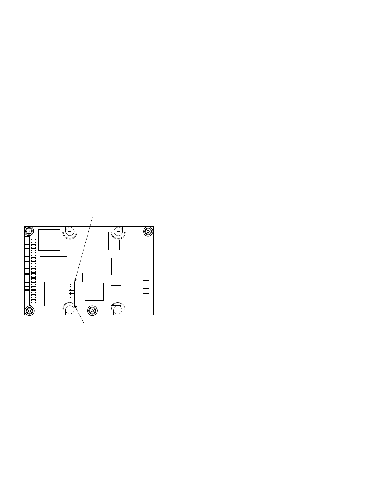
The vendor-specific pin field consists of pins A1–A4 and is
used for manufacturing testing purposes. As indicated in
Table 1, these vendor-specific pins should always be left
open.
Table 1 Vendor-Specific Pin Options
Pin Function Status
A1 Ground MFG test strap Leave open
A2 Test UART receive data Leave open
A3 +12 V for controller ROM Leave open
A4 Test UART transmit data Leave open
Note the Use of the ATA Signal Pins
The 44 ATA signals pins carry the ATA signals, power, and
grounds paths for the drive circuitry. Table 2 provides a list
of the signal names. For a full explanation of all the ATA
signal functions, refer to the ANSI ATA Specification.

4 DSP2022-A ATA/IDE Disk Drive Installation Guide
Table 2 Single-Ended ATA Signal Pins
Pin Signal Pin Signal
01 -RESET 02 SIGNAL GND
03 +DD7 04 +DD8
05 +DD6 06 +DD9
07 +DD5 08 +DD10
09 +DD4 10 +DD11
11 +DD3 12 +DD12
13 +DD2 14 +DD13
15 +DD1 16 +DD14
17 +DD0 18 +DD15
19 GND 20 KEY, (no pin)
21 RESERVED 22 SIGNAL GND
23 -DIOW 24 SIGNAL GND
25 -DIOR 26 SIGNAL GND
27 IORDY 28 CSEL
29 DMACK 30 SIGNAL GND
31 +INTRQ 32 -IOCS16
33 +DA1 34 -PDIAG
35 +DA0 36 +DA2
37 -CS1FX 38 -CS3FX
39 -DASP 40 SIGNAL GND
41 +5V CIRCUITS 42 +5V MOTOR
ACTUATOR
43 GND MOTOR
ACTUATOR 44 RESERVED

DSP2022-A ATA/IDE Disk Drive Installation Guide 5
Locate Jumper Connector J1
Locate jumper connector J1 on the electronic component
side of the drive shown in Figure 2. Note that connector
J1 contains eight jumper pairs numbered 0 through 7. Your
drive comes with all jumpers in place.
Figure 2 Location of Jumper Connector J1
JUMPER PAIR 0
JUMPER PAIR 7
J1
CXO-3498A-MC_R

6 DSP2022-A ATA/IDE Disk Drive Installation Guide
Learn the Jumper Functions
The jumper functions on the ATA drive are described in
Table 3. Note that jumper 0 is used for selecting single or
dual drive operation and that jumper 7 is used to prevent
the drive from entering manufacturing test mode if pin A1 is
momentarily grounded. Jumpers 1 through 6 are reserved
for future use and should always be left in place.
Table 3 Jumper Descriptions
Jumper Function Jumper Status
0 Single drive operation IN
Master drive in dual
operation IN
Slave drive in dual operation OUT
1 Reserved IN
2 Reserved IN
3 Reserved IN
4 Reserved IN
5 Reserved IN
6 Reserved IN
7 Prevents the manufacturing
test from being initiated if
ATA connector pin A1 is
grounded
OUT

DSP2022-A ATA/IDE Disk Drive Installation Guide 7
Select Single or Dual Drive Operation
With jumper 0 in place, your drive is set for single drive
operation, or as the master drive in dual drive operation.
If you wish to use this drive as the slave drive (drive D) in
dual drive operation, then remove jumper 0.
Remove Jumper 7
Remove jumper 7 to prevent the drive from entering
manufacturing test mode if pin A1 is grounded.
Obtain a mounting kit
Due to the large number of possible installation cabinets
and slot sizes, your drive does not come with an installation
kit of brackets, screws, and cables. You must obtain the
parts needed for your particular installation from your
distributor or purchasing source.

8 DSP2022-A ATA/IDE Disk Drive Installation Guide
Locate the Drive Mounting Holes
Two holes are provided on each side of the drive for side
mounting as shown in Figure 3. Four mounting holes are
provided on the bottom surface for bottom mounting as
shown in Figure 4.
Figure 3 Side Mounting Holes
M3 x 0.5
BOTH SIDES
.740 in
18.80 mm
.244 in
6.20 mm
1.500 in
38.10 mm
1.375 in
34.93 mm
CXO-3496A-MC_R
MOUNTING HOLE (2)

DSP2022-A ATA/IDE Disk Drive Installation Guide 9
Figure 4 Bottom Mounting Holes
1.500 in
38.10 mm
2.420 in
61.47 mm
.165 in
4.19 mm
4.000 in
101.60 mm
M3 x 0.05
1.375 in
34.93 mm
CXO-3495A-MC_R
MOUNTING HOLE SCREW (4)

10 DSP2022-A ATA/IDE Disk Drive Installation Guide
Use the Drive Mounting Guidelines
Use this list of drive mounting guidelines to prevent
mounting problems.
• The drive may be mounted in any orientation.
• Mounting screws should not penetrate the mounting
holes beyond the depths given in this list.
• Mounting screws are M3 X0.5 metric screws (3mm
diameter and 0.5 thread pitch).
• The recommended screw depth penetration of the
bottom mounting holes is 0.381 centimeters (0.15
inches).
• The recommended screw depth penetration of the side
mounting holes is 0.254 centimeters (0.1 inches).
Follow Connection Guidelines
Use these guidelines to connect to the DSP2022-A ATA
connector:
• Use a connector with pins on 2mm centers.
• Use a Molex 87259-5016 connector or its equivalent.
• Don’t exceed the recommended 2 foot cable length
maximum.
Follow ATA Interface Instructions
If the ATA interface is built into the computer, refer to the
computer’s installation guide for disk drive connection
instructions. If a separate interface adapter has been
installed, refer to the adapter installation guide for disk drive
connection instructions.

DSP2022-A ATA/IDE Disk Drive Installation Guide 11
Run the Setup Utility
When you are finished mounting the drive and attaching
the cables, you are ready to run the setup utility. You
need to run a setup utility to tell the system what type of
hardware is installed. To run the setup utility, follow the
setup instructions in your operating system manual or BIOS
manual.
This drive’s characteristics are not described by the 46
predefined BIOS drive types. Use BIOS type 47 (User
Defined Drive Type) to describe this drive. The default
values that describe this drive are provided in Table 4.
If your setup utility does not include the capability for a user
defined drive type, you can also use one of the pre-defined
drive types as long as the total capacity does not exceed
220.459 megabytes.
Table 4 Default Setup Values
Drive Characteristics Default Values
Number of cylinders 699
Number of heads 11
Write precomp 0 (not used)
Landing zone 699 (not used)
Sectors per track 56
Size (megabytes) 220.459
Bytes per sector 512

12 DSP2022-A ATA/IDE Disk Drive Installation Guide
Drive Specifications
The performance and environmental specifications for your
disk drive are listed in Table 5.
Table 5 Drive Specification Summary
Formatted Storage 220,000,000 bytes
Average Seek Time Less than 10 milliseconds
Typical spin up time Less than 12.5 seconds
Disk rotation speed 5400 RPM
Bytes per block 512
Height 0.75 in. (19.0 mm)
Length 4.0 in. (101.6 mm)
Width 2.75 in. (69.8 mm)
Weight 7.3 oz. (.20 kg.)
Voltage & regulation +5VDC +/- 5%
Active mode power Less than 5 watts
Operating Altitude -200 to + 10,000 feet
-61 to + 3,048 meters
Operating Temperature +40 to +131 degrees F
+5 to +55 degrees C
Table of contents
Other Digital Equipment DC Drive manuals
Popular DC Drive manuals by other brands

Iomega
Iomega REV 70 Quick install

YASKAWA
YASKAWA 1000 Series installation manual

York
York MILLENIUM 351-46 operating instructions

YASKAWA
YASKAWA 1000 Series Technical manual

Sumitomo Drive Technologies
Sumitomo Drive Technologies PARAMAX SFC Series Operating and maintenance manual

FAAC
FAAC T-MODE TM R E Series Quick installation guide