Digital Equipment 8504 User manual

85XX Series Network DVR User Manual……………………………………………………………………….V1.0
- 1 -
85XX Series Network DVR User Manual
8504/8504P
8508
H8504P/AH8504P
H8508/AH8508
8504FP/8508F/A8504FP 8504CP/8508C/A8504CP
/F8504FP/F8508F/A8508F F8504CP/F8508C/A8508C
PLEASE READ CAREFULLY AND SAVE
This manual contains important information about this product's operation. If you are installing this product for
others, you must leave this manual for a copy with the end user.
The DVR color included in the packing may be different from the user manual or packing.The picture is only for
reference

85XX Series Network DVR User Manual……………………………………………………………………….V1.0
- 2 -

85XX Series Network DVR User Manual……………………………………………………………………….V1.0
- 3 -
CONTENT
CHAPTER 1 INTRODUCTION ...............................................................................................4
1.1 MAIN FEATURE .............................................................................................................................................................4
1.2 PRODUCT FEATURES ......................................................................................................................................................4
1.2.1 Parameter..............................................................................................................................................................4
1.2.2 Working Environment...........................................................................................................................................5
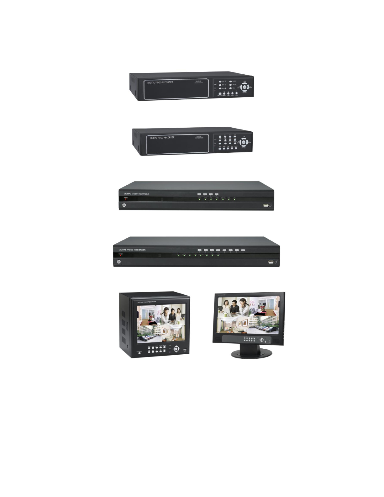
1.2.3 Device Environment..............................................................................................................................................5
CHAPTER 2 DEVICE OPERATION MANUAL ....................................................................6
2.1 CONTROL INSTRUCTION .................................................................................................................................................6
2.1.1 Remote Controller Instruction ................................................................................................................................6
2.1.2 Mouse Operation....................................................................................................................................................7
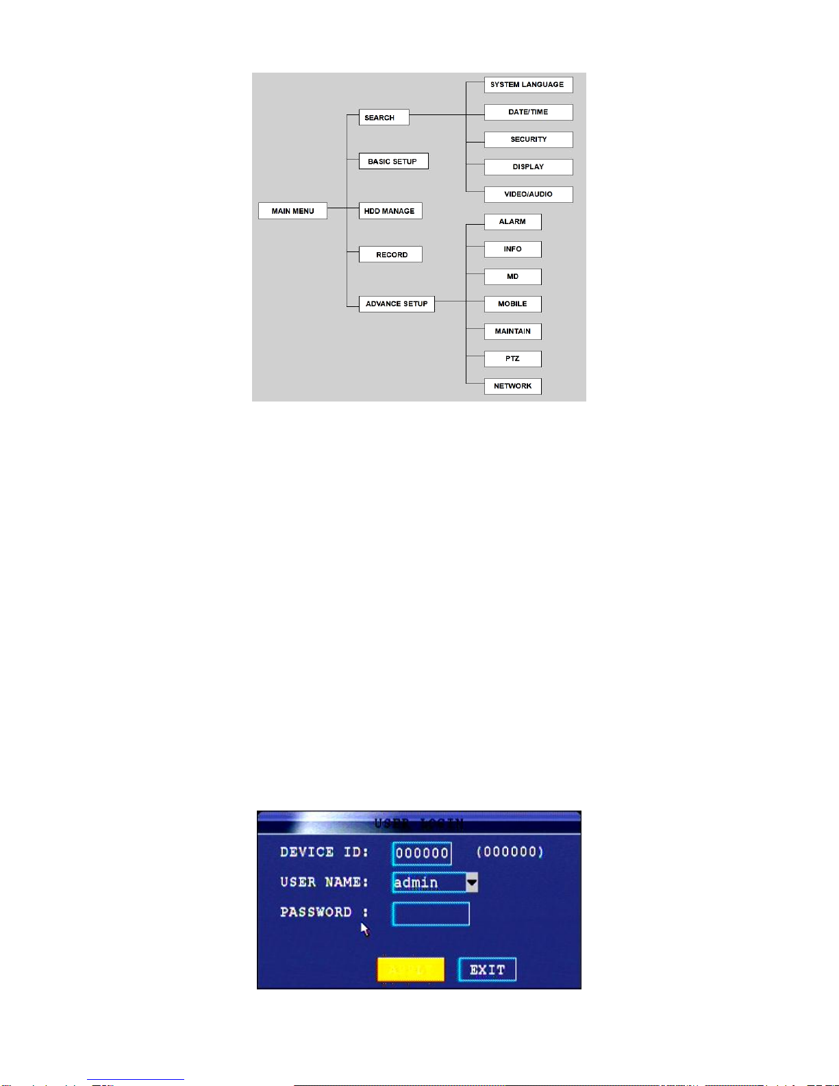
2.1.3 MENU CONFIGURATION...........................................................................................................................................7
2.2 SYSTEM OPERATION ......................................................................................................................................................8
2.2.1 START-UP............................................................................................................................................................8
2.2.2 SYSTEM LOGIN..................................................................................................................................................8
2.2.3 GUI OPERATION.................................................................................................................................................9
2.3 TOUCH-SCREEN MANUAL .............................................................................................................................................27
CHAPTER 3 IE REMOTE ACCESS......................................................................................30
3.1 FEATURES ...................................................................................................................................................................30
3.2 LOGIN .........................................................................................................................................................................30
3.3 IE BROWSER INTERFACE..............................................................................................................................................31
3.3.1 LIVE...................................................................................................................................................................32
3.3.2 Playback..............................................................................................................................................................33
3.3.3 Setup...................................................................................................................................................................35
4 VCA SOFTWARE OPERATION MANUAL......................................................................39
4.1 INSTALLATION.............................................................................................................................................................39
4.2 LOGIN.......................................................................................................................................................................42
4. 3SETUP .........................................................................................................................................................................45
4.4 VCA SETTING..............................................................................................................................................................65
5 DVR INSTALLATION GUIDELINE..................................................................................97
5.1FRONT PANEL..............................................................................................................................................................97
5.1.1 The Definition of Bottoms and Connectors on Front Panel....................................................................................97
5.1.2 The definition of buttons and connectors on rear panel.......................................................................................99
5.2 DVR HDD INSTALLATION DEMONSTRATION ...........................................................................................................104
5.2.1 HDD Installation..............................................................................................................................................104
CHAPTER 6 DEVICE PART................................................................................................ 105
6.1CHECK DEVICE PART .................................................................................................................................................105
CHAPTER 7 FAQ..................................................................................................................106
GUARANTEE........................................................................................................................110

85XX Series Network DVR User Manual……………………………………………………………………….V1.0
- 4 -
Chapter 1 INTRODUCTION
1.1 Main Feature
85XX series DVR is 4CH D1 and 8CH CIF resolution digital video recorder. Both of them have local
recording, playback, support treble code remote network surveillance, data backup, parameter setting, motion
detection, I/O alarm setting, PTZ and USB mouse.
1.2 Product features
Advanced Linux;
H.264 compression, support D1;
USB or IE to upgrade software;
PTZ and network function;
Support Multi-Language firmware;
Support mobile surveillance;
Support network center management system(CMS);
Applied in large surveillance area such as supermarket, gas station, factory etc.
1.2.1 Parameter
Content
Item
Instruction
System
Language
Multi-language
OSD
Friendly GUI OSD menu
Password
With six user groups for user and administractor
Video
Video Input
4/8CH BNC Input, with 1.0V p-p, 75Ω
Video Output
1CH BNC Output, with 1.0V p-p,75Ω
Video Display
4CH:1/4 channels display;
8CH: 1/4/9 channels display
Video System
PAL: 25fps/CH, CCIR625 line, 50Hz
NTSC: 30fps/CH, CCIR525 line, 60Hz
Audio
Audio Input
4/8CH RCA audio input, with 600Ω
Audio Output
1CH RCA audio output, with 600Ω
Output voltage
Linear voltage
Record mode
Support record with Video and Audio simultaneously
Audio
Compression
ADPCM
Video process and
save
Video
Compression
H.264
Resolution
CIF/HD1/D1
Video Standard
ISO14496-10
Audio Standard
ADPCM

85XX Series Network DVR User Manual……………………………………………………………………….V1.0
- 5 -
1.2.2 Working Environment
Item
Parameter
Instruction
Host Input Voltage
DC 12V
Video Input Resistance
75Ω
The resistance of each input channel is 75Ω.
Video Output
1Vp-p
Each channel for output is Vp-p with CVBS analog signal.
Working Temperature
-10----50℃
It’s the environment temperature around the DVR.
I/O Alarm Port
0—2V
It’s for low voltage alarm
5V-30V
It’s for high voltage alarm
RS485 Port
Connect PTZ through Pelco-D, Pelco-P protocol.
1.2.3 Device Environment
In order to make the DVR in long running and safe using, before install the DVR, please consider the following
Video bit rate
CIF: 384,512,768 Kbps
HD1: 512,768,1024 Kbps
D1:896,1024,1280Kbps
Audio bit rate
32KB/s
Data save mode
Support SATA HDD
Alarm
Alarm Input
4CH/8CH Alarm input
Alarm Output
1CH Alarm output
Communication port
Serial port
Support 1 RS485 port
Network port
NET port, 10M/100M adapt network port
USB
Mouse
USB2.0
USB Driver
USB2.0
VGA
VGA Output
Support 800×600,1024×768,1280×1024,1366×768,1440×900
Software
IE remote access
Install ActiveX for video preview, record download and configuration
of DVR
TFT Monitor
8504FP/8508F/A8504FP/A8508F/F8504FP/F8508F(8″Digital TFT)
8504CP/8508C/F8504CP/F8508C/A8504CP/A8508C(15.6″Digital
TFT)
Upgrade
Support USB driver or IE browser upgrade
Other
Power Adapters
Input Voltage
AC:110~240V
Power
6W (Without HDD and additional device)
Temperature
-10----50℃

85XX Series Network DVR User Manual……………………………………………………………………….V1.0
- 6 -
attention:
1. When install and operate the DVR, apply with the electrical standard request and connection requirement.
2. Make sure the power supply is connected to ground.
3. Do not touch the power supply adaptor and DVR in wet.
4. Do not drop the liquid onto the DVR device in order to avoid short circuit inside.
5. Do not lay on other heavy subjects to DVR.
6. Clear the DVR with soft cloth, and do not use chemical solvent.
7. If the DVR power supply and connection is correct, and the DVR is not able to start, it maybe the problem of
voltage, make sure the voltage is normal.
8. If the DVR will be rest in long time, it’s better to cut off the power supply and plug off the adaptor.
Chapter 2 Device operation manual
2.1 Control Instruction
2.1.1 Remote Controller Instruction
Handheld IR Controller Key Functions:
【0-9】keys: During setup, number keys are used to input values. For
viewing channels 1, 2, 3 and 4, use 1, 2, 3 and 4 on numeric keypad
respectively.
【+】,【-】keys: During setup, plus and minus are used to select next or
previous values.
,: Up, Down directional keys: Move selection up and down in setup
menu.
,: Left, Right directional keys: Move cursors left or right in setup menu.
【 】: Switch 4 Channels;
【 】: Fast forward the videowhile playback. press【 】to return to normal
speed;
【 】: Reverse the videowhile playback, press REW to switch, press【 】
to return to normal speed;
【STANDBY】: Reset the DVR to Power on off mode. (Standby and start up);
【LOGIN/LOCK】: If the security is enabled in the setup, use LOGIN/LOCK
key to enter the user setup. It is important to remember the password due to
without restoration function. Log in(to enter into “User ID select” and
“Password” input interface)and lock functions(To exit setup and operation).
【MENU】: Press OSD for main menu;
【PTZ】: PTZ control,press this key to enter into PTZ control interface when
at single live view;
【EXIT】: Exit to the preview or return to the last menu;
【RECORD】: Start manual record
【STOP】: Stop manual record
【ASISTANT】For future use

85XX Series Network DVR User Manual……………………………………………………………………….V1.0
- 7 -
2.1.2 Mouse Operation
You can use mouse to make operation of the menu besides IR remote controller. (The operation is the same as
PC Windows).Please inserts the mouse into USB Port.
Click right
key
Enter into main menu: Click the right key on the live view.
Click left key
Click the left key to enter into the setting interface.
Click the left key to zoom in the window on the live view and playback video. Double
click the left key can exit to the live view and playback multi-window interface.
1. Volume adjustment, color adjustment, PTZ setting and VGAborder operation. It
is for setting the single channel, PTZ control and color adjustment. If it is
multi-window, please use the left key to select the single window.
2. The remark when click the left key, color adjustment, VGAborder is as follow:
a.There are and for buttons the PTZ setting to adjust parameter, click
it can adjust the setting for PTZ.
b.There is a sticker to show the volume on the volume adjustment interface.
Move the mouse to the corresponding position and click the left key. The right
side of sticker will show the volume, click “x” to exit.
c.Color adjustment can refer to the volume adjustment interface operation.
When there are many options in the option frame, click left key to see down-pull
menu.
To click the left key on the playback interface can make >> means forward, <<
means raw, >>I means Slow play, I> means Pause frame play,> means Play, X
means exit.
Click left key
1. In the input frame, click the left key can activate the keyboard. The number,
symbol, English can be input by clicking the mouse.
2. Pinyin also can be input by the soft keyboard when enter Chinese, the method is
the same as remote control. You can use the left/right key to turn over the page
when check on Pinyin/Chinese word.
3. When input number, click the right key, the number soft keyboard will bob up first,
and then use the left key to select the corresponding numerical value. Also click the
left key to exit the number keyboard.
Mouse move
1. Press the left key to move the mouse can adjust the parameter on the volume,
color, VGA border interface. And the corresponding parameter will be display at the
same time.
2. In the Motion Detection setting interface, you can use the left key to drag the
frame to set the motion detection area.
Scroll-Wheel
Switch VGA and BGC
2.1.3 Menu Configuration
You can control the DVR by a lot of menu operation. This tree will show you the menu structure and it will be in
details in the following chapters.

85XX Series Network DVR User Manual……………………………………………………………………….V1.0
- 8 -
2.2 System Operation
2.2.1 START-UP
Connect the power adapter to DVR. When start up the DVR, 【POWER】LED will be on and 4 images will be
display on the screen. If it has setup ignition recording or time recording, the system will record automatically
and the corresponding LED will be on, and the system work normally.
Remark:
1. If there is no HDD in device, or the device didn’t read the HDD, or the HDD didn’t be formatted it will display
an 【H】in the video preview interface.
2. You must format the HDD in the DVR before first using. The steps as follows: menu > HDD management >
format. After formatting, the system will restart.
2.2.2 SYSTEM LOGIN
Remark: default device ID is: 00000, and there is no password. In order to keep safe, please modify the user
password and change the device ID in the base setup. You can setup user and admin password, Admin has all
authorities while user has limited authorities of viewing image, searching and play backing video. When you
input a password, the system will automatically match and offer different password with different authorities.
When DVR started, click right key by mouse. If you open a password, it will enter into user login interface. The
picture is as follows:

85XX Series Network DVR User Manual……………………………………………………………………….V1.0
- 9 -
Device ID: You just need to enter the device ID as the right frame.
Password: enter the admin password or user password.
2.2.3 GUI OPERATION
The main menu include “SEARCH”,”RECORD”,”HDD”,”BASIC”,“ADVANCE”, and “Exit”.
Remark: You must press “APPLY” to make the setting for submenu valid. It will be no use when exit directly.
There is a special feature of this DVR: when you move the mouse somewhere, the explanation information will
be showed automatically.
1. SEARCH: Search the record files, playback and backup the data;
2. RECORD: To set the record parameter;
3. HDD: To show the HDD running status and manage the HDD;
4. BASIC: To set Date and Time, Language, Video/Audio, Standard and User group;
5. ADVANCED: To set System, Alarm, PTZ, Network and Maintenance;
6. EXIT: To exit the main menu;
7. To show the information of instruction.
2.2.3.1 Search
2.2.3.1.1 Search record
Select 【SEARCH】to enter the search setting interface.
Input the date then click “SEARCH”, the record status will be shown as bellows,

85XX Series Network DVR User Manual……………………………………………………………………….V1.0
- 10 -
The first two lines is for Month, and the below three lines is for Day. The green color block is general record;
the red color block is alarm record.
Double click the day then system will playback the record for whole day. If click “FILE LIST”, the system will
show the record file list.
TYPE: The default is show all the channel;
SEARCH: To classify the record file through channel or time;
FIRST: To skip the file list to the first page;
PRE: To turn to the previous page;
NEXT: To turn to the next page;
LAST: To skip the file list to the last page;
ALL: To select all the record files in the list;
OTHER: To select all the record files except the current page;
BACKUP: To backup the selected file;
EXIT: To exit the file record interface.
2.2.3.1.2 Backup
Before backup, please prepare the USB Driver, which is better with capacity between 256MB to 32GB.
Backup steps:
A. Insert the USB Driver to the USB port on back panel, please make attention do not insert the port the

85XX Series Network DVR User Manual……………………………………………………………………….V1.0
- 11 -
USB mouse port;
B. Loin system and enter SEARCH menu, click FILE LIST to show the record files;
C. Select the record file you want to backup;
D. Click BACKUP to backup the data.
Please make sure the power supply is stable during backup, and make sure do not plug off the USB during
backup.
Remarks: If the free space of USB driver is not enough to save the backup data, the system will remind and
show the space is not enough.
2.2.3.2 Record
2.2.3.2.1 Record parameter
Select 【RECORD】to enter the record setting interface.

85XX Series Network DVR User Manual……………………………………………………………………….V1.0
- 12 -
Switch: Set the channel in ON or OFF status, that is to set the channel is open or close status.
Resolution: For 9504 DVR, there’re D1, HD1, CIF options;
For 9508 DVR, in CH1 and CH2, there’re D1, HD1, CIF options; and other channel only with HD1, CIF options.
Bitrate: There’re three options to be selected, L, M, H.
L->Low, the bit rate is as: CIF: 384 Kbps; HD1: 512 Kbps; D1: 896 Kbps;
M->Middle, the bit rate is as: CIF: 512 Kbps; HD1: 768 Kbps; D1: 1024 Kbps;
H->High, the bit rate is as: CIF: 768 Kbps; HD1: 1024 Kbps; D1: 1280 Kbps;
Frame Rate: The frame rate of image could be set, but the total frame rate is 200fps/PAL, 240fps/NTSC for
4CH, 400fps/PAL, 480fps/NTSC for 8CH. And the maximum frame rate for each channel is 25fps/PAL,
30fps/NTSC.
Note: 1 D1=4CIF, 1 HD1=2CIF.
Audio: To set the audio ON or OFF.
Rec. Mode:
POWER UP: the system will begin to record when DVR is start.
TIMER RECORD: the system will record as schedule.
Rec. Size: the system will process the record every 15minutes, 30minutes, 45minutes, and 60minutes.
Mask Area: to set the camera mask area in live demo.
After set the parameter, click APPLY to reserve and exit.
2.2.3.2.2 SCHEDULE RECORD
If select the record mode in TIME RECORD, the system will record as schedule. The user could set the time
duration to record.

85XX Series Network DVR User Manual……………………………………………………………………….V1.0
- 13 -
The time table shows one week and 0-23hrs in one day. Users could set the time duration as alarm record
(Red), normal record (Green), and no recording (Blue).
Schedule record steps:
A. Select the TIMER RECORD in RECORD menu.
B. Select the channel for schedule record.
C. Select the record mode, like Alarm, Normal record in Red or Green color.
D. Click the blue block in red or green color which to set the time duration you want to record in one day.
E. Select the day in “COPY TO” to click “COPY” button to copy the schedule record setting to other days in one
week.
F. Click APPLY to save the setting and exit.
For example, you want the system record from Monday to Friday and from 9:00 to 17:00 with all the channels,
and you also hope to record the alarm/MD record from 17:00 to 9:00. But do not record on Saturday and
Sunday.
Notice: In default settings, one week includes 7days, recording in succession for 24hrs.
Record time settings:
A. Select the TIMER RECORD in RECORD menu.
B. Select channels for “all”
C. Click the blue box (not record) under the time table, it will display “√”sign.
D. Move the cursor to 『SUN』, click the entire box from 00~23hrs, the box turned blue.
E. In “COPY TO” selection box choose Sunday, and in “set to” selection box choose Saturday, then click
“COPY” button.
F. Click the box in red (alarm recording) under the time table.
G. Move the cursor to 『MON』, click the entire box from 00~23hrs, the box turned red.
H. In “COPY TO” selection box choose Monday, and in “set to” selection box choose
Tuesday, then click “COPY” button. Keep the same copy to 『Wed』『 Thu』『 Fri』, the settings will display as
below:
I. Click APPLY to save the setting and exit
2.2.3.3 HDD Management
Select 【HDD】to enter the HDD management setting interface. It will display the system embedded HDD
basic information, and can format the HDD and U disk.

85XX Series Network DVR User Manual……………………………………………………………………….V1.0
- 14 -
HDD STATUS:
SIZE: shows HDD total capacity.
FREE SPACE: show the free space of HDD.
AVAILABLE TIME: show the remaining recording time depends on the video packing time you set.
OVERWRITE: there’re two options ENABLE or DISABLE.
If in ENABLE, and if the HDD capacity is full, the system will overwrite the previous record automatically.
If in DIABLE: and if the HDD capacity is full, system will stop recording and the “FULL” LED light on the front
panel will indicate on as well.
USB STATUS:
SIZE: show the USB driver total capacity.
FREE SPACE: show the free space of USB driver.
HDD FORMAT: to format the HDD. Notice: HDD format will delete all the video data. And the data will
NOT be recovered.
USB FORMAT: to format the USB driver. Before using USB driver to backup video data and upgrade the
firmware, we suggest format the USB first.
2.2.3.4 BASIC SETUP
Select 【BASIC】to enter the system basic information setting interface. Basic setup includes language,
date/time, password, display, and video/audio and exit six options.
2.2.3.4.1 Language

85XX Series Network DVR User Manual……………………………………………………………………….V1.0
- 15 -
SYSTEM LANGUAGE: Select the language and click APPLY, then system will restart.
Now the system is available for multiple language firmwares, such as English, Russian, Spanish, French, Thai
language etc.
2.2.3.4.2 DATE/TIME
Date and Time setup:
A. Input the date and time, and select the date format in TIME SETUP. Make sure the system date and time is
the same with computer when need to remote access from outside internet.
DATE: Press【Enter】or 【+】/【-】or press number key to choose the date.
DATE FORMAT: Press ENTER to switch between the date patterns, there are YY-MM-DD and MM/DD/YY two
options.
TIME: Press【Enter】or 【+】/【-】or press number key to choose the date.
TIME FORMAT: Press ENTER to switch between the date patterns, there are 12 HOURS and 24 HOURS two
options.
B. Click “SAVE DATE AND TIME” to reserve the date and time setting.
Zone: the time zone which the DVR device is in.
C. Click APPLY to save the setting, then the date and time setup will be reserve.
DST (Daylight Saving Time)
DST setup:
A. Select ON to open the DST。
B. There is User-defined and default mode to choose:
·User-defined:Skip to Step4

85XX Series Network DVR User Manual……………………………………………………………………….V1.0
- 16 -
·Default:In default, DST is from the 2nd Sun of March to 2nd Sun to November. (Skip to Step3)
C. Select default, click “enter” to setup.
D. Select user-defined mode, choose the corresponding week and month is OK.
E. Click “APPLY” to save and exit.
2.2.3.4.3 PASSWORD
When user starts the system in first time, system will identify with “000000” as the device serial number to login.
There are 2 users groups which are one admin group and 4 users group, and one device serial number.
Administrator: Have all the rights of system operation; click CONFIG to input the password.
User: only have the right to surveillance view, record searching, video playback and other restricted right. Click
CONFIG to input the password.
Remark: We strongly suggest you enable your system password for admin password and user password with
6 numeral numbers.
Notice: In default setting, the system is without password. Users can access any functions without any
password.

85XX Series Network DVR User Manual……………………………………………………………………….V1.0
- 17 -
User can change the device serial number, admin and user password in the password setting interface.
Open the Password interface:
A. right clicks anywhere to open the sub-menu, and select the main menu.
B. Select the basic setting in the interface。
C. Select the password to enter the user management interface.
Change the device serial number and password:
A. Click serial number and key into 6 numeral numbers (by mouse). For example: 000010.
B. Select “ON” to enable using password.。
C. Click user password and key into 6 numeral numbers (by mouse). In the corresponding field “enter again” to
save and confirm.
D. Click Admin password and key into 6 numeral number (by mouse). In the corresponding field “enter again”
to save and confirm.。
Notice: User password should not be the same as the one for admin.
E. Click “APPLY” to save and exit.
User can access the system menu by new password. And can also access the system through internet with
the admin and user password.
Delete network password: Delete the network password and click enter to save. The system will recover to IE
browser password.
2.2.3.4.4 DISPLAY
Through display menu to change the channel name, display/hide the view and playback time and date, and
enable/disable preview channel.

85XX Series Network DVR User Manual……………………………………………………………………….V1.0
- 18 -
NAME: input the new name through mouse or remote control.
POSITION: locate the channel name in live window; there are TOPLEFT, BOTTOMLEFT, TOPRIGHT,
BOTTOMRIGHT and OFF. Select OFF, the name will not be shown on the window.
COLOR: adjusting the chrome, brightness, contrast and saturation.
LIVE: there are ON/OFF option to display/hide the playback time and date.
PREVIEW TIME: there are ON/OFF options to display/hide the live time and date.
RECORD TIME: there are ON/OFF options to display/hide the playback time and date.
After set the parameter, click APPLY to save and exit.
2.2.3.4.5 VIDEO/AUDIO
Video/audio setup can set the resolution and camera system standard.
VGA resolution: there 800×600, 1024×768, 1280×1024, 1366×768, 1440×900 five options.
Camera system: there are NTSC and PAL systems standard.
Loop Time: to set the time to rotate the window when there’s only one live window.
Volume Setup: to setup the audio volume.
2.2.3.5 ADVANCED
Advance menu includes alarm, system information, motion detection, mobile, system maintenance, PTZ and
network setting.
2.2.3.5.1 ALARM

85XX Series Network DVR User Manual……………………………………………………………………….V1.0
- 19 -
I/O ALARM: show each channel alarm status, that is, when an alarm triggered, it will activate the
corresponding channel to start alarm recording.
NO: indicate alarm is Normal Open; it will be ON when have alarm
NC: indicate alarm is Normal Close; it will be OFF when there is a alarm
HDD LOSS: if ON, means it will trigger alarm if there is no HDD, and it will display【H】on the bottom of each
channel in the live window. If OFF, there will be not alarm, but still will show 【H】in live window.
HDD SPACE: if ON, if the space is less than 500M, there is remind window in live view: No enough space,
please change HDD after shutdown. If OFF, the system won’t alarm.
VIDEO LOSS: if on, when one channel loss video signal, it will display “video loss” in live view.
EMAIL SETUP: to send the snap pictures when there’s alarm.
TAMPER ALARM: to set the alarm on or off.
ALARM MANAGE: to manage the alarm output, buzzer and post record status.
OUTPUT: when alarm triggered, the output time will be: 0 second, 10 seconds, 20 seconds, 40 seconds or 60
seconds
BUZZER: to alarm in sound with 0 second, 10 seconds, 20 seconds, 40 seconds or 60 seconds when alarm is
triggered.
POST REC.: to continue record with time 30 seconds, 1 minute, 2 minutes or 5 minutes when alarm is
triggered.
EMAIL SETUP:
DVR system can send an email with JPEG snapshot once the system is triggered by events.

85XX Series Network DVR User Manual……………………………………………………………………….V1.0
- 20 -
EMAIL: to select ON to make the email alarm function.
SSL: one protocol of email, in SSL area, select “ON”.
SMTP port: input the email provider SMTP port.
SMTP server: input the email provider SMTP server address.
SEND EMAIL: input the email sending account.
SEND PW: input the password of above email.
RECV EMAIL: input the receiving email account.
After set as above, the SEND EMAIL will send the snap pictures to RECE EMAILaddress particularly.
2.2.3.5.2 INFO
Here to check the software version, SCM version, MAC address and serial number in system information.
2.2.3.5.3 MD (Motion Detection)
To set the motion detection for each channel.
STATUS: Select ON to active the motion detection function.
SENSITIVITY: There’re five options to set. The number is more, the sensitivity is easier to trigger.As usual, we
suggest 2.
MD Area: To select the motion detection area. Click SETUP to set. Each channel has corresponding regional
motion detecting setting, RED area means it have activated motion detection, transparent block means it have
not activated motion detection. Picture is below:
This manual suits for next models
18
Table of contents
Other Digital Equipment DVR manuals