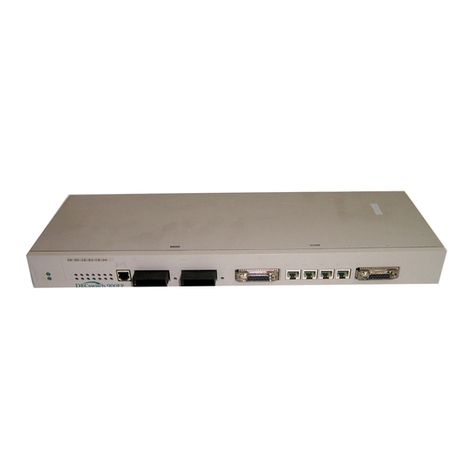
Digital Equipment DECswitch 900EF Operating and maintenance instructions

DECswitch 900EF
Installation and Configuration
Part Number: EK-DEFBA-IN. D01
May 1996
This manual describes how to install and configure the DECswitch 900EF module.
Revision/Update Information: This is a revised manual.

Digital Equipment Corporation makes no representations that the use of its products in the manner
described in this publication will not infringe on existing or future patent rights, nor do the descriptions
contained in this publication imply the granting of licenses to make, use, or sell equipment or software in
accordance with the description.
Possession, use, or copying of the software described in this publication is authorized only pursuant to a
valid written license from Digital or an authorized sublicensor.
© Digital Equipment Corporation 1996. All rights reserved.
The following are trademarks of Digital Equipment Corporation:
DEC, DECswitch, DECconnect, DEChub, DECnet, DEChub ONE, DEChub ONE-MX, DECnet,
MultiSwitch, clearVISN, ThinWire, and the DIGITAL logo.
The following are third-party trademarks:
AppleTalk is a registered trademark of Apple Computer, Inc.
Novell and IPX are registered trademarks of Novell, Inc.
All other trademarks and registered trademarks are the property of their respective holders.
FCC Notice — Class A Computing Device:
This equipment generates, uses, and may emit radio frequency energy. The equipment has been type
tested and found to comply with the limits for a Class A computing device pursuant to Subpart J of Part
15 of FCC Rules, which are designed to provide reasonable protection against such radio frequency
interference when operated in a commercial environment. Operation of this equipment in a residential
area may cause interference; in which case, measures taken to correct the interference are at the user’s
expense.
VCCI Notice — Class 1 Computing Device:
This equipment is in the 1st Class category (information equipment to be used in commercial and/or
industrial areas) and conforms to the standards set by the Voluntary Control Council for Interference by
Data Processing Equipment and Electronic Office Machines aimed at preventing radio interference in
commercial and/or industrial areas. Consequently, when used in a residential area or in an adjacent area
thereto, radio interference may be caused to radios and TV receivers. Read the instructions for correct
handling.
CE Notice — Class A Computing Device:
Warning!
This is a Class A product. In a domestic environment, this product may cause radio interference,in which
case the user may be required to take adequate measures.
Achtung!
Dieses ist ein Gerät der Funkstörgrenzwertklasse A. In Wohnbereichen können bei Betrieb dieses Gerätes
Rundfunkstörungen auftreten, in welchen Fällen der Benutzer für entsprechende Gegenma nahmen
verantwortlich ist.
Attention!
Ceci est un produit de Classe A. Dans un environment domestique, ce produit risque de créer des
interférences radioélectriques, il appartiendra alors à l’utilisateur de prendre les mesures spécifiques
appropriées.

iii
CONTENTS
Preface
Overview . . . . . . . . . . . . . . . . . . . . . . . . . . . . . . . . . . . . . . . . . . . . . . . . . . . . . . . . . . . . . . . . . . . . . ix
About this Manual . . . . . . . . . . . . . . . . . . . . . . . . . . . . . . . . . . . . . . . . . . . . . . . . . . . . . . . . . . ix
Intended Audience . . . . . . . . . . . . . . . . . . . . . . . . . . . . . . . . . . . . . . . . . . . . . . . . . . . . . . . . . . ix
Organization . . . . . . . . . . . . . . . . . . . . . . . . . . . . . . . . . . . . . . . . . . . . . . . . . . . . . . . . . . . . . . . .x
Associated Documents. . . . . . . . . . . . . . . . . . . . . . . . . . . . . . . . . . . . . . . . . . . . . . . . . . . . . . . . . . . xi
Conventions . . . . . . . . . . . . . . . . . . . . . . . . . . . . . . . . . . . . . . . . . . . . . . . . . . . . . . . . . . . . . . . . . . xiii
Overview. . . . . . . . . . . . . . . . . . . . . . . . . . . . . . . . . . . . . . . . . . . . . . . . . . . . . . . . . . . . . . . . . xiii
Correspondence . . . . . . . . . . . . . . . . . . . . . . . . . . . . . . . . . . . . . . . . . . . . . . . . . . . . . . . . . . . . . . . xiv
Documentation Comments . . . . . . . . . . . . . . . . . . . . . . . . . . . . . . . . . . . . . . . . . . . . . . . . . . . xiv
Online Services. . . . . . . . . . . . . . . . . . . . . . . . . . . . . . . . . . . . . . . . . . . . . . . . . . . . . . . . . . . . xiv
How to Order Additional Documentation . . . . . . . . . . . . . . . . . . . . . . . . . . . . . . . . . . . . . . . . . . . .xv
Safety
Overview . . . . . . . . . . . . . . . . . . . . . . . . . . . . . . . . . . . . . . . . . . . . . . . . . . . . . . . . . . . . . . . . . . . .xvii
1 Product Introduction
Overview . . . . . . . . . . . . . . . . . . . . . . . . . . . . . . . . . . . . . . . . . . . . . . . . . . . . . . . . . . . . . . . . . . . . 1-1
Introduction. . . . . . . . . . . . . . . . . . . . . . . . . . . . . . . . . . . . . . . . . . . . . . . . . . . . . . . . . . . . . . . 1-1
In this chapter . . . . . . . . . . . . . . . . . . . . . . . . . . . . . . . . . . . . . . . . . . . . . . . . . . . . . . . . . . . . . 1-1
What is the DECswitch 900EF?. . . . . . . . . . . . . . . . . . . . . . . . . . . . . . . . . . . . . . . . . . . . . . . . . . . 1-2
Features . . . . . . . . . . . . . . . . . . . . . . . . . . . . . . . . . . . . . . . . . . . . . . . . . . . . . . . . . . . . . . . . . . . . . 1-3
Hot Swap. . . . . . . . . . . . . . . . . . . . . . . . . . . . . . . . . . . . . . . . . . . . . . . . . . . . . . . . . . . . . . . . . 1-3
Configuration and Management . . . . . . . . . . . . . . . . . . . . . . . . . . . . . . . . . . . . . . . . . . . . . . . 1-3
Bridging . . . . . . . . . . . . . . . . . . . . . . . . . . . . . . . . . . . . . . . . . . . . . . . . . . . . . . . . . . . . . . . . . 1-4
FDDI/Ethernet . . . . . . . . . . . . . . . . . . . . . . . . . . . . . . . . . . . . . . . . . . . . . . . . . . . . . . . . . . . . 1-5
SNMP . . . . . . . . . . . . . . . . . . . . . . . . . . . . . . . . . . . . . . . . . . . . . . . . . . . . . . . . . . . . . . . . . . . 1-6
Remote MONitoring (RMON) . . . . . . . . . . . . . . . . . . . . . . . . . . . . . . . . . . . . . . . . . . . . . . . . 1-7
Virtual LANs . . . . . . . . . . . . . . . . . . . . . . . . . . . . . . . . . . . . . . . . . . . . . . . . . . . . . . . . . . . . . 1-8

iv
Front Panel Features . . . . . . . . . . . . . . . . . . . . . . . . . . . . . . . . . . . . . . . . . . . . . . . . . . . . . . . . . . . 1-9
Back Panel Features . . . . . . . . . . . . . . . . . . . . . . . . . . . . . . . . . . . . . . . . . . . . . . . . . . . . . . . . . . 1-12
2 Installing the Module
Overview. . . . . . . . . . . . . . . . . . . . . . . . . . . . . . . . . . . . . . . . . . . . . . . . . . . . . . . . . . . . . . . . . . . . 2-1
Introduction . . . . . . . . . . . . . . . . . . . . . . . . . . . . . . . . . . . . . . . . . . . . . . . . . . . . . . . . . . . . . . 2-1
In this chapter. . . . . . . . . . . . . . . . . . . . . . . . . . . . . . . . . . . . . . . . . . . . . . . . . . . . . . . . . . . . . 2-1
Installing the Module in a DEChub 900 . . . . . . . . . . . . . . . . . . . . . . . . . . . . . . . . . . . . . . . . . . . . 2-2
Task 1: Compare the Power Ratings. . . . . . . . . . . . . . . . . . . . . . . . . . . . . . . . . . . . . . . . . . . . . . . 2-3
Task 2: Seat the Module into the DEChub 900. . . . . . . . . . . . . . . . . . . . . . . . . . . . . . . . . . . . . . . 2-4
Task 3: Verify Initial LED Operation . . . . . . . . . . . . . . . . . . . . . . . . . . . . . . . . . . . . . . . . . . . . . . 2-5
Task 4: Connect the Port Cables . . . . . . . . . . . . . . . . . . . . . . . . . . . . . . . . . . . . . . . . . . . . . . . . . . 2-6
Task 4 (Cont.): Connect the FDDI Cables . . . . . . . . . . . . . . . . . . . . . . . . . . . . . . . . . . . . . . . . . . 2-7
Task 4 (Cont.): Connect the AUI Ethernet Cables . . . . . . . . . . . . . . . . . . . . . . . . . . . . . . . . . . . . 2-8
Task 4 (Cont.): Connecting the UTP/STP Cable . . . . . . . . . . . . . . . . . . . . . . . . . . . . . . . . . . . . . 2-9
3 Installing the Setup Port Cable
Overview. . . . . . . . . . . . . . . . . . . . . . . . . . . . . . . . . . . . . . . . . . . . . . . . . . . . . . . . . . . . . . . . . . . . 3-1
Introduction . . . . . . . . . . . . . . . . . . . . . . . . . . . . . . . . . . . . . . . . . . . . . . . . . . . . . . . . . . . . . . 3-1
In this chapter. . . . . . . . . . . . . . . . . . . . . . . . . . . . . . . . . . . . . . . . . . . . . . . . . . . . . . . . . . . . . 3-1
Signaling Standards. . . . . . . . . . . . . . . . . . . . . . . . . . . . . . . . . . . . . . . . . . . . . . . . . . . . . . . . . . . . 3-2
Setup Port Device Cabling . . . . . . . . . . . . . . . . . . . . . . . . . . . . . . . . . . . . . . . . . . . . . . . . . . . . . . 3-3
Connecting the Setup Port. . . . . . . . . . . . . . . . . . . . . . . . . . . . . . . . . . . . . . . . . . . . . . . . . . . . . . . 3-4
4 Setting Up and Configuring the Module in a DEChub ONE
Overview. . . . . . . . . . . . . . . . . . . . . . . . . . . . . . . . . . . . . . . . . . . . . . . . . . . . . . . . . . . . . . . . . . . . 4-1
Introduction . . . . . . . . . . . . . . . . . . . . . . . . . . . . . . . . . . . . . . . . . . . . . . . . . . . . . . . . . . . . . . 4-1
In this chapter. . . . . . . . . . . . . . . . . . . . . . . . . . . . . . . . . . . . . . . . . . . . . . . . . . . . . . . . . . . . . 4-1
Accessing the Setup Port. . . . . . . . . . . . . . . . . . . . . . . . . . . . . . . . . . . . . . . . . . . . . . . . . . . . . . . . 4-2
Using Menus to Setup the Module . . . . . . . . . . . . . . . . . . . . . . . . . . . . . . . . . . . . . . . . . . . . . . . . 4-3
[1] Reset with Factory Defaults . . . . . . . . . . . . . . . . . . . . . . . . . . . . . . . . . . . . . . . . . . . . . . . . . . 4-4
[2] Reset with Current Settings. . . . . . . . . . . . . . . . . . . . . . . . . . . . . . . . . . . . . . . . . . . . . . . . . . . 4-5
[3] Show Current Settings. . . . . . . . . . . . . . . . . . . . . . . . . . . . . . . . . . . . . . . . . . . . . . . . . . . . . . . 4-6
[4] Configure IP . . . . . . . . . . . . . . . . . . . . . . . . . . . . . . . . . . . . . . . . . . . . . . . . . . . . . . . . . . . . . . 4-7
[1] Set SNMP Read/Write Community . . . . . . . . . . . . . . . . . . . . . . . . . . . . . . . . . . . . . . . . . 4-8
[2] Add SNMP Trap Addresses . . . . . . . . . . . . . . . . . . . . . . . . . . . . . . . . . . . . . . . . . . . . . . . 4-9
[3] Delete SNMP Trap Addresses . . . . . . . . . . . . . . . . . . . . . . . . . . . . . . . . . . . . . . . . . . . . 4-10
[4] Set In-Band Interface IP Address. . . . . . . . . . . . . . . . . . . . . . . . . . . . . . . . . . . . . . . . . . 4-11

v
[5] Set Out-of-Band Interface IP Address . . . . . . . . . . . . . . . . . . . . . . . . . . . . . . . . . . . . . . 4-12
[6] Enable/Disable BootP . . . . . . . . . . . . . . . . . . . . . . . . . . . . . . . . . . . . . . . . . . . . . . . . . . . 4-13
[5] Dump Error Log . . . . . . . . . . . . . . . . . . . . . . . . . . . . . . . . . . . . . . . . . . . . . . . . . . . . . . . . . . 4-14
[6] Downline Upgrade . . . . . . . . . . . . . . . . . . . . . . . . . . . . . . . . . . . . . . . . . . . . . . . . . . . . . . . . 4-15
Before You Begin . . . . . . . . . . . . . . . . . . . . . . . . . . . . . . . . . . . . . . . . . . . . . . . . . . . . . . . . . 4-15
Assigning an IP Address. . . . . . . . . . . . . . . . . . . . . . . . . . . . . . . . . . . . . . . . . . . . . . . . . . . . 4-15
Using the DLU Process. . . . . . . . . . . . . . . . . . . . . . . . . . . . . . . . . . . . . . . . . . . . . . . . . . . . . 4-16
Initiaizing the Process. . . . . . . . . . . . . . . . . . . . . . . . . . . . . . . . . . . . . . . . . . . . . . . . . . . . . . 4-17
The DLU Process Stages . . . . . . . . . . . . . . . . . . . . . . . . . . . . . . . . . . . . . . . . . . . . . . . . . . . 4-18
If the Process Does not Complete. . . . . . . . . . . . . . . . . . . . . . . . . . . . . . . . . . . . . . . . . . . . . 4-20
When the DLU Process is Complete . . . . . . . . . . . . . . . . . . . . . . . . . . . . . . . . . . . . . . . . . . 4-21
Verifying the Upgrade . . . . . . . . . . . . . . . . . . . . . . . . . . . . . . . . . . . . . . . . . . . . . . . . . . . . . 4-21
[7] Out-of-Band Port Configuration . . . . . . . . . . . . . . . . . . . . . . . . . . . . . . . . . . . . . . . . . . . . . . 4-22
[8] Module-Specific Options . . . . . . . . . . . . . . . . . . . . . . . . . . . . . . . . . . . . . . . . . . . . . . . . . . . . 4-23
[1] Set FDDI Configuration . . . . . . . . . . . . . . . . . . . . . . . . . . . . . . . . . . . . . . . . . . . . . . . . . 4-24
[1] Set FDDI Configuration (Cont.) . . . . . . . . . . . . . . . . . . . . . . . . . . . . . . . . . . . . . . . . . . . 4-25
[2] Set Ethernet Configuration . . . . . . . . . . . . . . . . . . . . . . . . . . . . . . . . . . . . . . . . . . . . . . . 4-26
[3] Configure IPX Switch. . . . . . . . . . . . . . . . . . . . . . . . . . . . . . . . . . . . . . . . . . . . . . . . . . . 4-27
5 Configuring the Module in a DEChub 900
Overview . . . . . . . . . . . . . . . . . . . . . . . . . . . . . . . . . . . . . . . . . . . . . . . . . . . . . . . . . . . . . . . . . . . . 5-1
Introduction. . . . . . . . . . . . . . . . . . . . . . . . . . . . . . . . . . . . . . . . . . . . . . . . . . . . . . . . . . . . . . . 5-1
In this chapter . . . . . . . . . . . . . . . . . . . . . . . . . . . . . . . . . . . . . . . . . . . . . . . . . . . . . . . . . . . . . 5-1
DEChub 900 MultiSwitch Installation Menu . . . . . . . . . . . . . . . . . . . . . . . . . . . . . . . . . . . . . . . . 5-2
[9] Start Redirect Mode . . . . . . . . . . . . . . . . . . . . . . . . . . . . . . . . . . . . . . . . . . . . . . . . . . . . . . . . . 5-3
Using Menus to Setup the Module. . . . . . . . . . . . . . . . . . . . . . . . . . . . . . . . . . . . . . . . . . . . . . . . . 5-4
[1] Reset with Factory Defaults . . . . . . . . . . . . . . . . . . . . . . . . . . . . . . . . . . . . . . . . . . . . . . . . . . . 5-5
[2] Reset with Current Settings . . . . . . . . . . . . . . . . . . . . . . . . . . . . . . . . . . . . . . . . . . . . . . . . . . . 5-6
[3] Show Current Settings . . . . . . . . . . . . . . . . . . . . . . . . . . . . . . . . . . . . . . . . . . . . . . . . . . . . . . . 5-7
[4] Configure IP . . . . . . . . . . . . . . . . . . . . . . . . . . . . . . . . . . . . . . . . . . . . . . . . . . . . . . . . . . . . . . 5-8
[1] Set SNMP Read/Write Community . . . . . . . . . . . . . . . . . . . . . . . . . . . . . . . . . . . . . . . . . 5-9
[2] Add SNMP Trap Addresses . . . . . . . . . . . . . . . . . . . . . . . . . . . . . . . . . . . . . . . . . . . . . . 5-10
[3] Delete SNMP Trap Addresses . . . . . . . . . . . . . . . . . . . . . . . . . . . . . . . . . . . . . . . . . . . . 5-11
[4] Set In-Band Interface IP Address . . . . . . . . . . . . . . . . . . . . . . . . . . . . . . . . . . . . . . . . . . 5-12
[5] Set Out-of-Band Interface IP Address . . . . . . . . . . . . . . . . . . . . . . . . . . . . . . . . . . . . . . 5-13
[6] Enable/Disable BootP . . . . . . . . . . . . . . . . . . . . . . . . . . . . . . . . . . . . . . . . . . . . . . . . . . . 5-14
[5] Dump Error Log . . . . . . . . . . . . . . . . . . . . . . . . . . . . . . . . . . . . . . . . . . . . . . . . . . . . . . . . . . 5-15
[6] Downline Upgrade . . . . . . . . . . . . . . . . . . . . . . . . . . . . . . . . . . . . . . . . . . . . . . . . . . . . . . . . 5-16
Before You Begin . . . . . . . . . . . . . . . . . . . . . . . . . . . . . . . . . . . . . . . . . . . . . . . . . . . . . . . . . 5-16
Assigning an IP Address. . . . . . . . . . . . . . . . . . . . . . . . . . . . . . . . . . . . . . . . . . . . . . . . . . . . 5-16
Using the DLU Process. . . . . . . . . . . . . . . . . . . . . . . . . . . . . . . . . . . . . . . . . . . . . . . . . . . . . 5-17
Initiaizing the Process. . . . . . . . . . . . . . . . . . . . . . . . . . . . . . . . . . . . . . . . . . . . . . . . . . . . . . 5-18
The DLU Process Stages . . . . . . . . . . . . . . . . . . . . . . . . . . . . . . . . . . . . . . . . . . . . . . . . . . . 5-19
vi
If the Process Does not Complete . . . . . . . . . . . . . . . . . . . . . . . . . . . . . . . . . . . . . . . . . . . . 5-22
When the DLU Process is Complete . . . . . . . . . . . . . . . . . . . . . . . . . . . . . . . . . . . . . . . . . . 5-23
Verifying the Upgrade . . . . . . . . . . . . . . . . . . . . . . . . . . . . . . . . . . . . . . . . . . . . . . . . . . . . . 5-23
[7] Module-Specific Options. . . . . . . . . . . . . . . . . . . . . . . . . . . . . . . . . . . . . . . . . . . . . . . . . . . . 5-24
[1] Configure IPX Switch . . . . . . . . . . . . . . . . . . . . . . . . . . . . . . . . . . . . . . . . . . . . . . . . . . 5-25
[2] Run Extended Diagnostics . . . . . . . . . . . . . . . . . . . . . . . . . . . . . . . . . . . . . . . . . . . . . . . 5-26
6 Removing the Module
Overview. . . . . . . . . . . . . . . . . . . . . . . . . . . . . . . . . . . . . . . . . . . . . . . . . . . . . . . . . . . . . . . . . . . . 6-1
Introduction . . . . . . . . . . . . . . . . . . . . . . . . . . . . . . . . . . . . . . . . . . . . . . . . . . . . . . . . . . . . . . 6-1
In this chapter. . . . . . . . . . . . . . . . . . . . . . . . . . . . . . . . . . . . . . . . . . . . . . . . . . . . . . . . . . . . . 6-1
Removing the Cables . . . . . . . . . . . . . . . . . . . . . . . . . . . . . . . . . . . . . . . . . . . . . . . . . . . . . . . . . . 6-2
Unseating the Module . . . . . . . . . . . . . . . . . . . . . . . . . . . . . . . . . . . . . . . . . . . . . . . . . . . . . . . . . . 6-3
A Problem Solving
Overview. . . . . . . . . . . . . . . . . . . . . . . . . . . . . . . . . . . . . . . . . . . . . . . . . . . . . . . . . . . . . . . . . . . . A-1
Introduction . . . . . . . . . . . . . . . . . . . . . . . . . . . . . . . . . . . . . . . . . . . . . . . . . . . . . . . . . . . . . . A-1
In this appendix . . . . . . . . . . . . . . . . . . . . . . . . . . . . . . . . . . . . . . . . . . . . . . . . . . . . . . . . . . . A-1
LED Descriptions . . . . . . . . . . . . . . . . . . . . . . . . . . . . . . . . . . . . . . . . . . . . . . . . . . . . . . . . . . . . . A-2
Problem Solving Using LEDs. . . . . . . . . . . . . . . . . . . . . . . . . . . . . . . . . . . . . . . . . . . . . . . . . . . . A-5
B Connector and Pin Assignments
Overview. . . . . . . . . . . . . . . . . . . . . . . . . . . . . . . . . . . . . . . . . . . . . . . . . . . . . . . . . . . . . . . . . . . . B-1
Introduction . . . . . . . . . . . . . . . . . . . . . . . . . . . . . . . . . . . . . . . . . . . . . . . . . . . . . . . . . . . . . . B-1
In this appendix . . . . . . . . . . . . . . . . . . . . . . . . . . . . . . . . . . . . . . . . . . . . . . . . . . . . . . . . . . . B-1
Connector Assignments. . . . . . . . . . . . . . . . . . . . . . . . . . . . . . . . . . . . . . . . . . . . . . . . . . . . . . . . . B-2
Optical Bypass Relay (6-pin MJ) Connector. . . . . . . . . . . . . . . . . . . . . . . . . . . . . . . . . . . . . B-2
10BaseT (8-pin MJ) Port Connector . . . . . . . . . . . . . . . . . . . . . . . . . . . . . . . . . . . . . . . . . . . B-3
AUI (15-pin D-Sub) Port Connector. . . . . . . . . . . . . . . . . . . . . . . . . . . . . . . . . . . . . . . . . . . B-4
H8571-J Adapter . . . . . . . . . . . . . . . . . . . . . . . . . . . . . . . . . . . . . . . . . . . . . . . . . . . . . . . . . . B-5
H8575-A Adapter. . . . . . . . . . . . . . . . . . . . . . . . . . . . . . . . . . . . . . . . . . . . . . . . . . . . . . . . . . B-5
Internal and External Crossover Configurations. . . . . . . . . . . . . . . . . . . . . . . . . . . . . . . . . . . . . . B-6
C Product Specifications
Overview. . . . . . . . . . . . . . . . . . . . . . . . . . . . . . . . . . . . . . . . . . . . . . . . . . . . . . . . . . . . . . . . . . . . C-1
Introduction . . . . . . . . . . . . . . . . . . . . . . . . . . . . . . . . . . . . . . . . . . . . . . . . . . . . . . . . . . . . . . C-1

vii
In this appendix. . . . . . . . . . . . . . . . . . . . . . . . . . . . . . . . . . . . . . . . . . . . . . . . . . . . . . . . . . . .C-1
Operating Specifications . . . . . . . . . . . . . . . . . . . . . . . . . . . . . . . . . . . . . . . . . . . . . . . . . . . . . . . .C-2
Acoustical Specifications. . . . . . . . . . . . . . . . . . . . . . . . . . . . . . . . . . . . . . . . . . . . . . . . . . . . . . . .C-4
D Accessing and Configuring RMON Groups
Overview . . . . . . . . . . . . . . . . . . . . . . . . . . . . . . . . . . . . . . . . . . . . . . . . . . . . . . . . . . . . . . . . . . . .D-1
Introduction. . . . . . . . . . . . . . . . . . . . . . . . . . . . . . . . . . . . . . . . . . . . . . . . . . . . . . . . . . . . . . .D-1
In this appendix. . . . . . . . . . . . . . . . . . . . . . . . . . . . . . . . . . . . . . . . . . . . . . . . . . . . . . . . . . . .D-1
What is RMON?. . . . . . . . . . . . . . . . . . . . . . . . . . . . . . . . . . . . . . . . . . . . . . . . . . . . . . . . . . . . . . .D-2
Groups Supported . . . . . . . . . . . . . . . . . . . . . . . . . . . . . . . . . . . . . . . . . . . . . . . . . . . . . . . . . . . . .D-3
How to Access RMON Groups . . . . . . . . . . . . . . . . . . . . . . . . . . . . . . . . . . . . . . . . . . . . . . . . . . .D-4
Accessing Statistics and History. . . . . . . . . . . . . . . . . . . . . . . . . . . . . . . . . . . . . . . . . . . . . . .D-4
Accessing Alarms and Events. . . . . . . . . . . . . . . . . . . . . . . . . . . . . . . . . . . . . . . . . . . . . . . . .D-4
Alarm and Event Table Entries. . . . . . . . . . . . . . . . . . . . . . . . . . . . . . . . . . . . . . . . . . . . . . . .D-5
How Traps Work . . . . . . . . . . . . . . . . . . . . . . . . . . . . . . . . . . . . . . . . . . . . . . . . . . . . . . . . . .D-7
Figures
Front Panel LEDs and Connectors. . . . . . . . . . . . . . . . . . . . . . . . . . . . . . . . . . . . . . . . . . . . . . . . 1-10
Back Panel Layout . . . . . . . . . . . . . . . . . . . . . . . . . . . . . . . . . . . . . . . . . . . . . . . . . . . . . . . . . . . 1-13
Module Power Ratings. . . . . . . . . . . . . . . . . . . . . . . . . . . . . . . . . . . . . . . . . . . . . . . . . . . . . . . . . 2-3
Seating the Module . . . . . . . . . . . . . . . . . . . . . . . . . . . . . . . . . . . . . . . . . . . . . . . . . . . . . . . . . . . 2-4
LED Location. . . . . . . . . . . . . . . . . . . . . . . . . . . . . . . . . . . . . . . . . . . . . . . . . . . . . . . . . . . . . . . . . 2-5
FDDI Cables . . . . . . . . . . . . . . . . . . . . . . . . . . . . . . . . . . . . . . . . . . . . . . . . . . . . . . . . . . . . . . . . 2-7
AUI Cable Connection. . . . . . . . . . . . . . . . . . . . . . . . . . . . . . . . . . . . . . . . . . . . . . . . . . . . . . . . . 2-8
UTP/STP Cable Connection . . . . . . . . . . . . . . . . . . . . . . . . . . . . . . . . . . . . . . . . . . . . . . . . . . . . 2-10
Device, Cable and Connector Identification . . . . . . . . . . . . . . . . . . . . . . . . . . . . . . . . . . . . . . . . 3-5
Cable Removal. . . . . . . . . . . . . . . . . . . . . . . . . . . . . . . . . . . . . . . . . . . . . . . . . . . . . . . . . . . . . . . 6-2
Unseat the Module. . . . . . . . . . . . . . . . . . . . . . . . . . . . . . . . . . . . . . . . . . . . . . . . . . . . . . . . . . . . 6-3
Optical Bypass Relay Connector Pin Assignments . . . . . . . . . . . . . . . . . . . . . . . . . . . . . . . . . . . B-2
10BaseT (8-pin MJ) Connector . . . . . . . . . . . . . . . . . . . . . . . . . . . . . . . . . . . . . . . . . . . . . . . . . . B-3
AUI 15-Pin Port Connector . . . . . . . . . . . . . . . . . . . . . . . . . . . . . . . . . . . . . . . . . . . . . . . . . . . . . B-4
H8571-J Adapter . . . . . . . . . . . . . . . . . . . . . . . . . . . . . . . . . . . . . . . . . . . . . . . . . . . . . . . . . . . . . B-5
H8575-A Adapter. . . . . . . . . . . . . . . . . . . . . . . . . . . . . . . . . . . . . . . . . . . . . . . . . . . . . . . . . . . . . B-5
Crossover Configurations . . . . . . . . . . . . . . . . . . . . . . . . . . . . . . . . . . . . . . . . . . . . . . . . . . . . . . B-6

viii
Tables
Front Panel LEDs and Connectors . . . . . . . . . . . . . . . . . . . . . . . . . . . . . . . . . . . . . . . . . . . . . . . . 1-9
Front Panel LEDs and Connectors . . . . . . . . . . . . . . . . . . . . . . . . . . . . . . . . . . . . . . . . . . . . . . . 1-11
Back Panel Feature Descriptions. . . . . . . . . . . . . . . . . . . . . . . . . . . . . . . . . . . . . . . . . . . . . . . . . 1-12
DLU Process Description . . . . . . . . . . . . . . . . . . . . . . . . . . . . . . . . . . . . . . . . . . . . . . . . . . . . . . 4-18
DLU Process Description . . . . . . . . . . . . . . . . . . . . . . . . . . . . . . . . . . . . . . . . . . . . . . . . . . . . . . 5-20
LED States. . . . . . . . . . . . . . . . . . . . . . . . . . . . . . . . . . . . . . . . . . . . . . . . . . . . . . . . . . . . . . . . . . A-3
FDDI PHY LEDs . . . . . . . . . . . . . . . . . . . . . . . . . . . . . . . . . . . . . . . . . . . . . . . . . . . . . . . . . . . . A-4
Typical Combined States of LEDs . . . . . . . . . . . . . . . . . . . . . . . . . . . . . . . . . . . . . . . . . . . . . . . A-6
Pin Assignments . . . . . . . . . . . . . . . . . . . . . . . . . . . . . . . . . . . . . . . . . . . . . . . . . . . . . . . . . . . . . . B-2
10BaseT (8-pin MJ) Connector Pin Assignments. . . . . . . . . . . . . . . . . . . . . . . . . . . . . . . . . . . . . B-3
AUI 15-Pin Port Connector Pin Assignments. . . . . . . . . . . . . . . . . . . . . . . . . . . . . . . . . . . . . . . . B-4
Operating Environment. . . . . . . . . . . . . . . . . . . . . . . . . . . . . . . . . . . . . . . . . . . . . . . . . . . . . . . . . C-2
Connector Specifications. . . . . . . . . . . . . . . . . . . . . . . . . . . . . . . . . . . . . . . . . . . . . . . . . . . . . . . . C-2
Physical Specifications . . . . . . . . . . . . . . . . . . . . . . . . . . . . . . . . . . . . . . . . . . . . . . . . . . . . . . . . . C-3
Certification. . . . . . . . . . . . . . . . . . . . . . . . . . . . . . . . . . . . . . . . . . . . . . . . . . . . . . . . . . . . . . . . . . C-3
Acoustical Specifications . . . . . . . . . . . . . . . . . . . . . . . . . . . . . . . . . . . . . . . . . . . . . . . . . . . . . . . C-4
Aktuelle Werte für spezielle Produkt . . . . . . . . . . . . . . . . . . . . . . . . . . . . . . . . . . . . . . . . . . . . . . C-5
Alarm Table Entry Fields . . . . . . . . . . . . . . . . . . . . . . . . . . . . . . . . . . . . . . . . . . . . . . . . . . . . . . D-6
Event Table Entries . . . . . . . . . . . . . . . . . . . . . . . . . . . . . . . . . . . . . . . . . . . . . . . . . . . . . . . . . . . D-7

ix
Preface
Overview
About this Manual
This manual describes how to install the DECswitch 900EF in a DEChub 900
MultiSwitch. (How to install the DECswitch 900EF in the DEChub ONE docking
station is described in the DEChub ONE Installation manual.) This manual also
describes how to configure the DECswitch 900EF software to operate in either a
DEChub 900 MultiSwitch or as a standalone module in a DEChub ONE docking
station.
Intended Audience
This manual is intended for use by personnel who will install and configure the
DECswitch 900EF module.

x
OrganizationThis manual is organized as follows:
Section Description
1 Provides an overview of the DECswitch 900EF, describes its
features, and lists front and back panel features.
2 Provides instructionsfor installingthe module in aDEChub900
MultiSwitch.
3 Provides instructions for installing the setup port cable.
4 Provides instructions for configuring the module in a DEChub
ONE.
5 Provides instructions for configuring the module in a DEChub
900 MultiSwitch.
6 Provides instructions for removing the module from a DEChub
900 MultiSwitch.
A Provides installation-specific troubleshooting information
using the LEDs.
B Provides connector and pin assignment information.
C Provides product specifications.
D Provides instructions for accessing the RMON groups.

xi
Associated Documents
The following documents provide information relating to the module. To order any of
the following documents, refer to the section titled How to Order Additional
Documentation.
Title and Order
Number Description
Ethernet Switch
Enterprise RMON
Upgrade
Configuration
AA-QXWAA-TH
Provides information for installing and configuring full
RMON firmware upgrade that supports all nine RMON
groups plus additional proprietary RMON MIBs.
DEChub 900
MultiSwitch
Owner’s Manual
EK-DH2MS-OM
Provides installation, use, security, and troubleshooting
information for the DEChub 900 MultiSwitch.
DEChub ONE
Installation
EK-DEHU2-IN
Provides installation and operation guidelines for
standalone module configuration, including mounting
options and cabling.
DEChub ONE MX
Installation
EK-DEF1H-IN
Provides installation and operation guidelines for
standalone module configuration, including mounting
options and cabling.
clearVISN
Installation Describes how to install clearVISN software. It includes
a list of distribution kit contents, system requirements,
pre-installation considerations, and the installation
procedure.
clearVISN
Product Overview Provides an overview of clearVISN, an explanation of
each clearVISN application, and descriptions of all
conceptsnecessary to understand and use the application
efficiently.
clearVISN
Configuration and
Use
Provides information for starting each application,
configuring then (when necessary), and general use
information.
Open DECconnect
Applications Guide
EC-G2570-42
Provides information to help plan and install networking
systems based on Digital’s OPEN DECconnect System
and networking products.

xii
DEChub Network
Modules 900-Series
Switch Reference
EK-SWTCH-HR
Describes the functions and features of Digital’s HUB-
based 900-Series switching products.
Bridge and
Extended
LAN Reference
EK-DEBAM-HR
Describes how bridges are used to create extended local
area networks (LANs). This includes the use of bridges
in extended LAN configurations, information on LAN
interconnections, overall bridge operation, spanning
tree, and solving bridge-related problems in a network.
Title and Order
Number Description

xiii
Conventions
Overview This book uses the following conventions.
Convention Description
Bold Type Indicates user input
Monospaced Type Indicates system output
16.20.54.156 The format of an IP address is the standard 4-
octet dotted decimal notation, where each
octet of the address is represented as a
decimal value, separated by a decimal point
(.).
Italics In examples, indicates user input.
[ ] Contain default responses to the installation
menu prompts.
<Return> Indicates that you press the Return Key.
Ethernet The Digital’s term for its product’s
compatibility with the ISO 8801-3/ANSI/
IEEE 802.3 standards and the Ethernet
standards for Carrier Sense Multiple Acc4ess
with Collision Detection (CSMA/CD) local
area networks (LANs).
08-00-2B-A3-00-00 This format represents a Media Access
Control (MAC) address in examples and
figures.

xiv
Correspondence
Documentation Comments
If you have comments or suggestions about this document, send them to the Network
Products Business Organization.
Attn.: Documentation Project Manager
FAX: (508) 486-6093
E-MAIL: doc_feed[email protected].dec.com
Online Services
To locate product specific information, refer to the following online services:
BBS To read the Bulletin Board System, set your modem to 8 bits, no parity, 1 stop bitand
dial 508-486-5766 (U.S.)
WWW The Digital Equipment Corporation Network Products Business Home Page on the
World Wide Web is at the following addresses:
North America: http://www.networks.digital.com
Europe: http://www.networks.europe.digital.com
Australia: http://www.digital.com.au/networks

xv
How to Order Additional Documentation
To order additional documentation, use the following information.
To Order: Contact:
By Telephone USA (except Alaska, New Hampshire, and Hawaii):
1-800-DIGITAL (1-800-344-4825)
Alaska, New Hampshire, and Hawaii: 1-603-884-6660
Canada: 1-800-267-6215
Electronically
(USA. only) Dial 1-800-DEC-DEMO
(For assistance, call 1-800-DIGITAL)
By Mail
(USA and
Puerto Rico)
DIGITAL EQUIPMENT CORPORATION
P.O. Box CS2008
Nashua, New Hampshire 03061
(Place prepaid orders from Puerto Rico with the local Digital
subsidiary: 809-754-7575)
By Mail
(Canada) DIGITAL EQUIPMENT of CANADA LTD.
940 Belfast Road
Ottawa, Ontario, Canada K1G 4C2
Attn.: A&SG Business Manager
Internationally DIGITAL EQUIPMENT CORPORATION
Attn.: A&SG Business Manager
c/o local Digital subsidiary or approved distributor
Internally U.S. Software Supply Business (SSB)
DIGITAL EQUIPMENT CORPORATION
10 Cotton Road
Nashua, New Hampshire 03063

xvi

xvii
Safety
Overview
Any warning or caution that appears in this manual is defined as follows:.
WARNING Contains information to prevent personal injury.
CAUTION Contains information to prevent damage to
equipment.
VORSICHT Enthält Informationen, die beachtet werden müssen
um den Benutzer vor Schaden zu bewahren.
ACHTUNG Enthält Informationen, die beachtet werden müssen
um die Gerate vor Schaden zu bewahren
DANGER Signale les informations destinées à prévenir les
accidents corporels.
ATTENTION Signale les informations destinées à prévenir la
détérioration du matériel.
AVISO Contiene información para evitar daños personales.
PRECAUCIÓN Contiene información para evitar daños al equipo.

xviii
The cautions that must be observed for the hardware described inthis manual are listed
below in English, German, French, and Spanish.
CAUTION This action deletes all configured settings and
replaces them with factory default values. All
configuration settings will be lost.
ACHTUNG Bei diesem Vorgang werden alle
Konfigurationseinstellungen gelöscht und die
Werkseinstellungen wieder eingesetzt. Alle
Konfigurationsdaten gehen verloren.
ATTENTION Cette action supprime tous les paramètres de
configuration et les remplace par des valeurs
prédéfinies. Tous les paramètres de configuration
seront perdus.
PRECAUCIÓN Esta intervención borrará todos los parámetros de
configuracióny lossustituirá porvalorespordefecto
definidos de fábrica. Se perderán todos los
parámetros de configuración.
WARNING Toprevent personalinjuryorequipmentdamage,do
not insert telecommunications cabling into the
Optical Bypass Relay connector.
VORSICHT Um Personen oder Geräteschäden zu vermeiden,
dürfen Sie das Telefonkabel Auf Keinen Fall am
Anschluß des optischen Bypass-Relais anschließen.
DANGER Pour éviter tout risque d'accident corporel ou de
dommage matériel, Ne Branchez Pas de câble de
télécommunication sur le connecteur de relais
sélectif optique.
AVISO Para evitar daños personales o al equipo,No se debe
introducir cableado de telecomunicaciones en el
conector óptico de relés de derivación.

xix
WARNING Some fiber optic equipment can emit laser or infrared
light that can injure your eyes. Never look into an optical
fiber or connector port. Always assume the cable is
connected to a light source.
VORSICHT Bestimmte Lichtleitergeräte können für die Augen
gefährliches Laser- oder Infrarotlicht abstrahlen.
Vermeiden Sie es daher unterallen Umständen, direkt in
ein Lichtleiterkabel oder einen Lichtleiteranschluß zu
schauen. Gehen Sie immer davon aus, daß
Lichtleiterkabel mit einer Lichtquelle verbunden sind.
DANGER Certains équipements à fibre optique peuvent émettre un
rayonnementlaser ou infra-rouge pouvantprovoquer des
troubles oculaires. Ne regardez jamais à l'intérieur d'une
fibre optique ou d'un port de connecteur. Considérez que
le câble est connecté en permanence à une source
lumineuse.
AVISO Ciertos equipos de fibras ópticas pueden emitir luz
lasérica o infrarroja con riesgos de lesiones en los ojos.
No se debe nunca mirar en una fibra óptica o una puerta
de conexión. Siempre hay que suponer que el cable está
conectado a una fuente luminosa.

xx
CAUTION If power is interrupted during Stage 3 of the DLU process,
the firmware image can become corrupted. Do not turn off
power to the unit or perform any action that can cause the
unit to lose power during Stage 3 of the DLU process.
ACHTUNG Solite während der Phase 3 des DLU-Prozesses eine
Unterbrechung der Stromversorgung eintreten, kann das
Firmwareprogramm zerstört verden. Aus diesem Grunde
wird dringend empfohlen, Vorkehrungen zu treffen, daß
während der Durchführung dieser Phase 3 die
Systemeinheit weder ausgeschaltet noch die
Stromversorgung unterbrochen werden kann.
ATTENTION L’image du microprogramme risque d’être corrumpue, en
cas de coupure de courant au cours de l’étape 3 du
processus DLU. Ne mettez pas l’unité hors tension et
n’exécutez aucune action risquant d’entraîner une coupure
d’alimentation au course de cette étape.
PRECAUCIÓN Si se interrumpe el suministro eléctrico durante la Etapa 3
del proceso DLU,. puede dañarse la imagen del firmware.
No se debe apagar la unidad ni realizar ninguna operación
que pueda causar una interrupción del suministro de la
unidad durante la Etapa 3 del mencionado proceso.
Other manuals for DECswitch 900EF
2
Table of contents
Other Digital Equipment Network Router manuals

Digital Equipment
Digital Equipment DECbrouter 90 User manual

Digital Equipment
Digital Equipment DECswitch 900EE Operating and maintenance instructions

Digital Equipment
Digital Equipment DECswitch 900EF Operating and maintenance instructions

Digital Equipment
Digital Equipment DECswitch 900EE User manual

Digital Equipment
Digital Equipment DECswitch 900EF Operating and maintenance instructions

Digital Equipment
Digital Equipment DEC WANrouter 90 User manual