4
Part 3: Configuring the Module
©Digital Equipment Corporation, 1997. All rights reserved.
clearVISN, DEChub, DIGITAL, and the DIGITAL logo are trademarks of Digital Equipment Corporation.
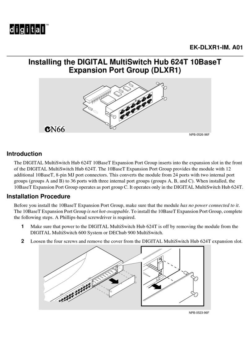
4Firmly push the module onto the backplane connector.
5Press down on the release lever to lock the module into place. Check that the module is fully
seated and secure.
6Ensure that the module’s Power OK and Module OK LEDs are on.
7Connect any modular media cables and the10BaseT cables. See Procedure 3: Cable the Mod-
MACs on page 2 and Procedure 4: Cable the 10BaseT Ports on page 2.
8Configure the module in the DIGITAL MultiSwitch 600. See Part 3: Configuring the
Module.
Step Action
1Select the appropriate cable and, if necessary, an adapter for your setup port device.
Normally, this is a BN24H-xx cable and an H8571-J (6-pin MMJ to a 9-pin D-Sub
connector) or H8575-A (6-pin MMJ to 25-pin D-Sub connector) adapter.
2Connect a terminal to the setup port on the Stack Station (if in an unmanaged environment),
Stack Director, or DEChub 900 MultiSwitch.
3Ensure that the transmit and receive baud rates on the setup port device are set to 9600.
4Stack Station only: Press Return on the setup port device until the Digital
MultiSwitch 612EX INSTALLATION menu appears.
5Stack Director or DEChub 900 only: Select option 9to start redirect mode. Enter the slot
number of the module. The console will be redirected to the module. The DIGITAL
MultiSwitch 612EX menu appears.
6From the DIGITAL MultiSwitch 612EX menu, select the desired menu item. For example,
select 3to see the current settings. Press Return to return to the main installation menu.
7Stack Station only: Select 5to configure the module’s product-specific options.
Stack Director or DEChub 900 only: Use clearVISN MultiSwitch Manager or clearVISN
MultiChassis Manager to configure the product-specific options.
8Restart the module in order for the changes to take effect.
Step Action
