3
3.
1
3.2
3.2.1
3.3
4
4.
1
4.2
4.2.1
4.2.2
4.3
4.4
4.5
4.6
4.7
4.8
5
5.
1
5.2
5.3
5.3.1
5.3.2
5.4
Figure
1-1
1-2
1-3
1-4
1-5
DECTAPE
TRANSPORT
TU55
CON
TEN
TS (Continued)
OPERATION
.•••.•..••..•••••...•.•••.•.••••.••.•..•...
'
..•..•........
Introduction
....•.•...•...••.•....................•.
'
..........•...
Controls and Indicators
...•..........•....••......•........•........
Operating
Notes
....•.•....•..••.•.•....•..••...•..•••..•.....
Loading Tape
........•.......••.•.•.•........•.•..•.......•..•...•
MAINTENANCE
•..•....•..•.........••...••.............•.•......••..
Equipment Required
•.•.•..••...•..•..••••.•..•...•.•.•
','
••..••••..•
Preventive
Maintenance
•••••••.•.••..•..•.•.•......•..•..•.•..•....
Weekly Schedule
...•.•...•••......•.....•.•...••..•..•.•...•..
Monthly Schedule
..•.••.••••.••.•..••...••...•................
Tape Tension and Transport Stop
Ad
justment
.•••.•.•.•.•.•.•.•..•..•.•.
Head
Output
Check
..•..•••••.••.•...•.••..•.••••.••.•..••.••••.•.
Head-Skew
Check
..•.•••..••••.••••....•.••..•.••••••••.•.•.•..••.
WRITE
ENABLE
Circuit
Check
.••••••..•.••..••.•.••.••...••.••••..••
Troubl eshooti
ng
••.••.•..•••••••.•...•.••.•...•.••••...•...•.•..•..
Recommended Spares
..•.••••••••••.•..•.•••••••••.•.•.•..•••..•••••
ENGINEERING DRAWINGS
••.•••••.••••••.•..••••..•.••••.••••..•••••.
Introduction
.•••••••••••••••••••.•••..••••••••.••.•.••...••••••.••
Circuit Symbols
......•.•........•.•......•....••..•.•.••..••••.•••
Logic Signal Symbols
..•.•.••.••.••.•..••.•••.•.•..•....•........•.
Logic Levels
.•..•..•..•.•..••••.•....•••....•......•..••......
FLIP
CH
IP
Pulses
.•..••••••..•••..••••••••.•••••••.•....•••....
Semiconductor Substitution .........................................
ILLUSTRATIONS
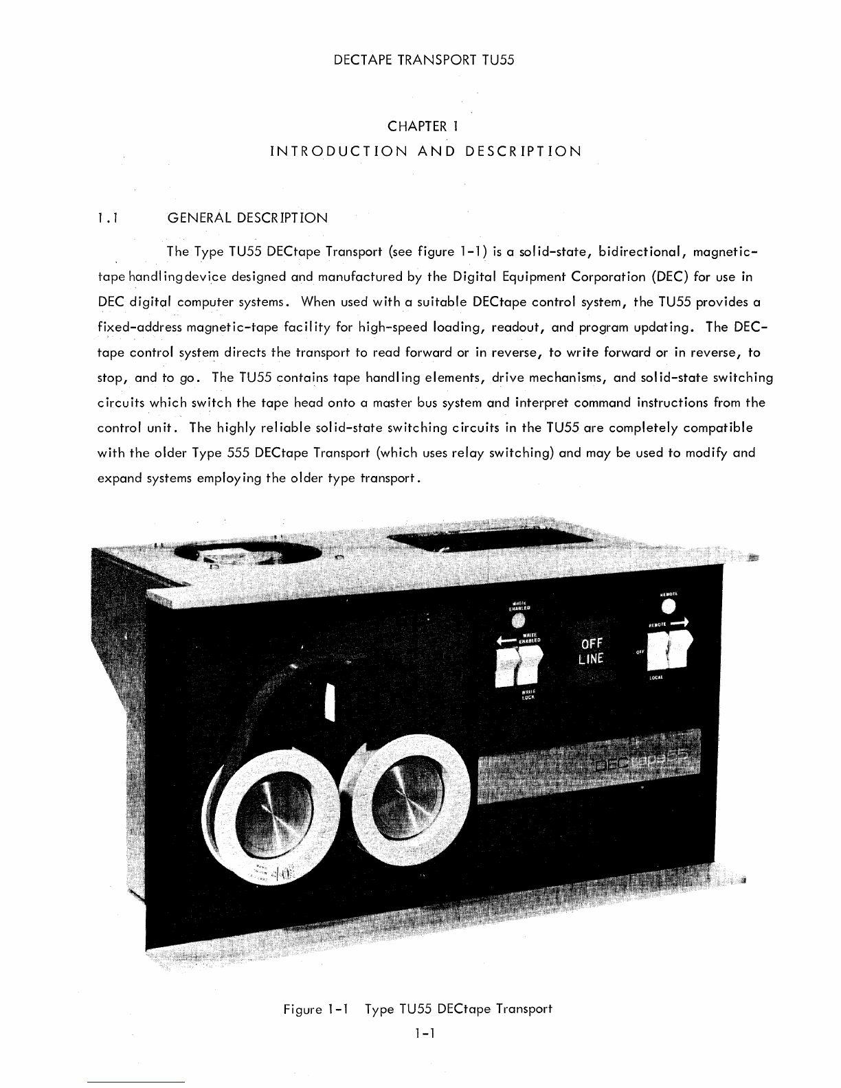
Type
TU55
DECtape Transport
••.•.•.••••..•...•••.•..••...•.••..•..•.•..
Hub and
Reel
Assembly
......................•..........................
Arrangement
of
DEC
tape
Head
.••••.••...•••....•...•....•.•.••..••.....
Type
TU55
DECtape TransportI Rear View
.•••••..•.•••.•••...•.......•.••.
TU55 Interface Connections
.•....•••.•••••.•••..••.••••.•••••••.•.•.••••
iv
Page
3-1
3-1
3-1
3-1
3-1
4-1
4-1
4-1
4-1
4-2
4-2
4-3
4-4
4-5
4-6
4-7
5-1
5-1
5-1
5-1
5-1
5-1
5-4
1- 1
1-5
1-6
1-7
1-8