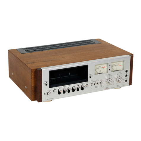
Pioneer CT1270WR User manual

Waster.
STEREO
DOUBLE
CASSETTE
TAPE
DECK
CT-1270WR
Operating
Instructions
Thank
you
for
buying
this
Pioneer
product.
Please
read
through
these
operating
instructions
so
you
will
know
how
to
operate
your
model
properly.
After
you
have
inished
reading
the
instructions,
put
them
away
in
a
safe
place
for
future
reference.
In
some
countries
or
regions,
the
shape
of
the
power
plug
and
power
outlet
may
sometimes
differ
from
that
shown
in
the
ex-
planatory
drawings.
However,
the
method
of
connecting
and
operating
the
unit
is
the
same.
xh
LINE
VOLTAGE
SELECTOR
SWITCH
Only
multi-voltage
modets
are
provided
with
this
switch.
U.S.,
Canadian,
European,
U.K.,
and
Australian
models
are
not
provided
with
this
switch.
The
line
voltage
selector
switch
is
on
the
rear
panel.
Before
your
model
is
shipped
from
the
factory,
this
switch
is
set
to
WARNING:
to
prevent
FIRE
OR
SHOCK
HAZARD,
DO
NOT
EXPOSE
THIS
APPLIANCE
TO
RAIN
OR
MOISTURE.
IMPORTANT
NOTICE
[For
U.S.
and
Canadian
models]
The
serial
number
for
this
equipment
is
located
on
the
rear
panel.
Please
write
this
serial
number
on
your
enclosed
war-
ranty
card
and
keep
in
a
secure
area.
This
is
for
your
security.
the
power
requirements
of
the
destination.
Check
that
it
is
set
properly
before
plugging
the
power
cord
into
the
AC
outlet.
if
the
voltage
is
not
properly
set
or
if
you
move
to
an
area
where
the
voltage
requirements
differ,
adjust
the
selector
switch
as
follows.
1.
Disconnect
the
power
cord.
2.
Use
a
medium-size
screwdriver.
3.
Insert
the
screwdriver
into
the
groove
on
the
voltage
selec-
tor,
and
adjust
so
that
the
tip
of
the
arrow
points
to
the
voltage
value
of
your
area.
=,
Medium-size
screwdriver
“This
product
is
manufactured
‘to
comply
with
the
radio
ine
terference
requirements
of
EEC
Directive
76/889/EEC
and
82/499/
EEC.”
QMPIONEER’

SAFETY
INSTRUCTIONS
READ
INSTAUCTIONS
--
All
the
safety
and
operating
instructions
should
be
read
before
the
appliance
is
operated.
RETAIN
INSTRUCTIONS
--
The
operating
instruc-
tions
should
be
retained
for
future
reference.
HEED
WARNING
—
All
warnings
on
the
appliance
and
in
the
operating
instructions
should
be
adhered
to.
FOLLOW
INSTRUCTIONS
—
All
operating
and
use
instructions
should
be
followed.
WATER
AND
MOISTURE
—
The
appliance
should
not
be
used
near
water
—
for
example,
near
a
bathtub,
washbow/,
kitchen
sink,
laundry
tub,
in
a
wet
basement,
or
near
a
swimming
pool,
etc.
LOCATION
—
The
appliance
should
be
installed
in
s
stable
location.
WALL
OR
CEILING
MOUNTING
—
The
appliance
should
not
be
mounted
to
a
waill
or
ceiting.
VENTILATION
—
The
appliance
should
be
situated
so
that
its
location
or
position
does
not
interfere
with
its
proper
ventilation.
For
example,
the
appliance
should
not
be
situated
on
a
bed,
sofa,
rug,
oF
similar
surface
that
may
block
the
ventilation
open-
ings;
of,
placed
in
a
built-in
installation,
such
as
a
bookcase
or
cabinet
that
may
impede
the
flow
of
air
through
the
ventilation
openings.
HEAT
—
The
apptiance
should
be
situated
away
from
heat
sources
such
as
radiators,
heat
registers,
stoves,
or
other
appliances
(including
amplifiers)
that
produce
heat.
POWER
SOURCES
-
The
appliance
should
be
con-
nected
to
a
power
supply
only
of
the
type
describ-
ed
in
the
operating
instructions
or
as
marked
on
the
appliance.
POWER-CORD
PROTECTION
—
Power-supply
cords
should
be
routed
so
that
they
are
not
likely
to
be
walked
on
or
pinched
by
items
placed
upon
or
against
them,
paying
particular
attention
to
cords
at
plugs,
convenience
receptacles,
and
the
point
POWER
LINES
—
An
outdoor
antenna
should
be
located
away
from
power
fines.
NONUSE
PERIODS
—
The
power
cord
of
the
ap-
pliance
should
be
unplugged
from
the
outlet
when
ieft
unused
for
a
tong
period
of
time.
OBJECT
AND
LIQUID
ENTRY
—
Care
should
be
taken
so
that
objects
do
not
fall
and
liquids
are
not
spilled
into
the
enclosure
through
openings.
DAMAGE
REQUIRING
SERVICE
—
The
appliance
should
be
serviced
by
Pioneer
authorized
service
center
or
qualified
service
personnel
when:
*
The
power-supply
cord
or
the
plug
has
been
damaged;
or
©
Objects
have
fallen,
or
liquid
has
been
spilled
into
the
appliance;
or
‘The
applisnce
has
been
exposed
to
rain;
or
The
appliance
does
not
appear
to
operate
normally
or
exhibits
a
marked
change
in
performance;
or
©
The
appliance
has
been
dropped;
or
the
enclosure
damaged.
SERVICING
—
The
user
should
not
attempt
to
service
the
appliance
beyond
that
described
in
the
‘operating
instructions.
For
all
other
servicing,
con-
tact
the
nearest
Pioneer
authorized
service
center.
POWER
LUNES.
seavice
ENTRANCE
CONDUCTORS
+
OUTDOOR
ANTENNA
GROUNDING
—
If
an
outside
antenna
is
connecied
to
the
antenna
terminal,
be
sure
the
antenna
system
is
grounded
so as
to
provide
some
protection
against
voliage
surges
and
built
up
static
‘charges.
In
the
U.S.A.
section
810
of
the
National
Elac-
trical
Code,
ANSI/NFPA
No.
70-1984,
pra-
vides
information
with
respect
to
proper
grounding
of
the
mast_and
supporting
struc-
ture,
grounding
of
the
fead-in
wire
to
an
anten-
na
discharge
unit,
size
of
grounding
conduc-
tors,
location
of
antenna-discharge
unit,
con-
nection
to
grounding
electrodes,
and
re-
quirements
for
the
grounding
electrode.
See
Fig.
A.
a)
Use
No.
10
AWG
(6.3
mm?)
copper,
No.
8
AWG
(8.4
mm}
aluminum,
No.
17
AWG
(1.0
mm)
copper-
clad
steel,
bronze
wire,
or
farger
as
ground
wit
b)
Secure
antenna
fead-in
and
STAND-OFF
ground
wires
to
house
with
INSULATORS
&
stand-off
insulators
spaced
from
4
feet
(1,22
meters}
to
6
feet
(1.83
meters)
apart.
¢)
Mount
antenna
discharge
where
they
exit
from
the
appliance.
POLARIZATION
—
If
your
purchased
product
Is
pro-
“
vided
with
a
polarized
power
plug,
please
read
the
following
instructions.
This
product
is
equipped
with
a
polarized
alternating
current
line
plug
(a
plug
-
having
one
blade
wider
than
the
other).
This
plug
seinen
unit
as
closely
as
possible
to
{ES
tne
where
lead-in
enters
house.
d)
Use
jumper
wite
not
smaller
than
No.6
AWG
(13.3
rm?)
copper
or
equivalent
when
ANTENNA,
separata
antenna-ground:
TO
EXTERNAL
ANTENNA
TERMINALS
OF
PRODUCT
will
fit
into
the
power
outlet
only
one
way.
This
is
a
SIGaARGE
unr
©
ing
electrode
is
used.
safety
feature.
If
you
are
unable
to
insert
the
plug
Foursewr
“aici
fully
into
the
outlet,
try
reversing
the
plug.
If
the
WIRE
ab
plug
should
stil
fail
to
fit,
contact
your
electrician
to
replace
your
obsolete.
outlet.
Do
not
defeat
the
safety
purpose
of
the
polarized
plug.
power
sence
CLEANING
—
The
appliance
shoutd
be
cleaned
only
Some
enn
cers
{lg.
mieriny
metal
water
ioe!
with
a
polishing
cloth
or
a
soft
dry
cloth.
Never
QPTIONAL
ANTENNA
‘GROUNONG
ELECTRODE
F
‘
3
4
clean
with
furniture
wax,
benzine,
insecticides
or
frien
RIVER
8
FEET
2.44
mt
other
volatile
fiquids
since
they
may
corrode
the
fo
aunesr
cabinet.
FIG.A
WU
_NEC
SECTION
€10
23
1H,
IMPORTANT
1
The
lightning
flash
with
arrowhead,
within
an
equilateral
triangle,
is
intended
to
alert
the
user
of
the
presence
of
uninsulated
“dangerous
voltage”
within
the
product's
enclosure
that
may
be
of
sufficient
magnitude
to
constitute
a
risk
of
electtic
shock
to
persons.
IMPORTANT
2
If
the
apparatus
is
fitted
with
AC
mains
power
outlet(s),
see
REAR
PANEL
FACILITIES
for
convenient
connec-
tion
of
additional
Hi-Fi
components}.
Make
all
connec-
tions
to
the
AC
outiet(s)
and
the
signal
terminals
first.
Connect
the
plug
to
the
wall
socket
last,
make
sure
that
the
power
switch
is
off,
Disconnect
the
wall
plug
when
the
equipment
is
not
in
(regular)
use,
e.g.
when
on
vacation.
2
RRBCO3>
CAUTION
RISK
OF
ELECTRIC
SHOCK
DO
NOT
OPEN
CAUTION:
TO
PREVENT
THE
RISK
OF
ELECTRIC
SHOCK,
DO
NOT
REMOVE
COVER
(OR
BACK}.
NO
USER-
SERVICEABLE
PARTS
INSIDE.
REFER
SERVIC-
ING
TO
QUALIFIED
SERVICE
PERSONNEL.
FOR
USE
IN
THE
UNITED
KINGDOM
WARNING:
This
plug
must
only
be
connected
to
electronic
apparatus
equipped
with
suitable
sockets.
If
not,
cut
off
the
plug
and
fit
an
appropriate
type
in
accordance
with
the
instructions
below.
The
cut-off
plug
must
be
disposed
of
as
an
elec-
trical
shock
hazard
could
exist
if
connected
to
a
socket
outlet.
The
exclamation
point
within
an
equilateral
triangle
is
intended
to
alert
the
user
of
the
presence
of
important
operating
and
maintenance
(servicing)
instructions
in
the
literature
accompanying
the
appliance.
The
wires
in
this
mains
lead
are
coloured
in
accordance
with
the
following
code:
Blue:
Neutral
Brown:
Live
As
the
colours
of
the
wires
in
the
mains
lead
of
this
ap.
paratus
may
not
correspond
with
the
coloured
marking
identifying
the
terminals
in
your
plug
proceed
as
follows:
The
wire
which
is
coloured
blue
must
be
connected
to
the
terminal
which
is
marked
with
the
letter
N
or
cai-
oured
black.
The
wire
which
is
coloured
brown
must
be
connected
to
the
terminal
which
is
marked
with
the
Jetter
L
or
col-
oured
red.

Features
Preparations
and
Connections
Front Panel
Facilities
How
to
Handle
Cassette
Tapes
.
Noise
Reduction
System
.
Recording
........::::.cc0
Playback:
we
ccccescosscbaceceditectiyvactes
sieeeeidas
i
ddwecncedeeeey
CONTENTS
Relay
Playback
..
Tape
Copying
...
Recording
and
Playback
Using
Audie
Timer
..
Maintenance
Troubleshooting
Specifications
FEATURES
®
Double
deck
equipped
with
auto
reverse
mechanism
(record/playback
deck+
exclusive
playback
deck)
operated
by
soft-push
button.
Dolby
B
and
C
Noise
Reduction
Normal
and
High-Speed
Dubbing
Functions
Relay
Play
for
Extended
Playback
Timer
Stand-by
Functions
Music
Scan
PREPARATIONS
AND
CONNECTIONS
CONNECTING
THE
CASSETTE
TAPE
DECK
TO
AN
AMPLIFIER
®
Read
through
the
operating
instructions
of
the
stereo
components
which
you
intend
to
connect
to
this
unit.
®
Turn
on
the
power
only
after
all
the
connections
are
completed.
®
The
top
jacks
are
for
the
left
(L)
channel;
the
bottom
jacks
are
for
the
right
(R)
channel.
®
Make
sure
that
the
plugs
are
inserted
securely.
Im-
proper
connection
may
generate
noise.
e
Avoid
placing
the
unit
directly
on
top
of
an
amplifier
since
this
may
cause
humming
or
other
noise.
®
Avoid
installing
the
unit
too
close
to
a
TV
set
since
humming
can
arise
during
recording
operations.
pp
uESk
ACCESSORIES
————
Connection
cord
with
pin
plugs
x
2
|
|
CT-1270WR
Playback
connections
Recording
connections
it
NOTE:
iC
he
HMustration
not
applicable
to
U.K.
model.
=e
IE
Heupe
elds
ute
When
using
an
audio
timer
{
Audio
timer
Jac
JE
Household
AC
outiet
3
<RAB1I003>

FRONT
PANEL
FACILITIES
POWER
(STAND-BY)
switch
|
NOTE:
The
unit's
POWER
switch
is
designed
to
select
the
transformer’s
secondary
and
so
even
at
the
STAND-BY
position,
the
unit’s
cir-
cuitry
will
work
as
long
as
the
power
cord
is
connected
to
power
outlet,
Disconnect
the
power
cord
from
the
power
outlet
when
you
do
nat
plan
to
use
the
unit
for
a
long
period
of
time.
Deck
Il
Reverse
MODE
switch
Deck
|
Reverse
MODE
switch
(=
Vposition
I
=e
Set
to
this
position
for
playback
or
recording
of
only
one
side
{
=D
)
position
of
the
cassette.
The
deck
will
stop
automatically
when
the
tape
Set
to
this
position
to
play
back
both
sides
of
the
cassette.
reaches
the
end.
When
the
tape
reaches
the
end
during
playback
in
the
FWD
{
=)
position
direction,
the
deck
wil!
automatically
reverse
directions
and
playback
the
other
side
of
the
cassette.
When
the
tape
reaches
the
end
in
the
REV
direction,
the
deck
will
stop
automatically.
Set
to
this
position
for
playback
or
recording
of
both
sides
of
the
cassette.
When
the
tape
reaches
the
end
during
playback
Start
playback
from
the
FWD
direction
to
play
back
both
sides
{or
recording)
in
the
FWD
direction,
the
deck
will
automatically
of
the
tape
automatically.
reverse
directions
and
play
back
(or
record)
the
other
side
of
the
cassette.
When
the
tape
reaches
the
end
in
the
REV
direc-
(CID)
position
tion,
the
deck
will
stop
automatically.
Playback
(or
recording}
Set
to
this
position
to
play
back
both
sides
of
the
tape
con-
must
be
started
from
the
FWD
direction
in
order
for
the
auto-
tinuously.
reverse
function
to
work.
Deck
Il
{for
playback/recording)
Deck
1
(for
playback)
|
Deck
il
DIRECTION
lever
Deck
i
Tape
direction
indicators
Use
to
change
the
playback/recording
direction
of
Deck
H.
Each
time
this
lever
is
pushed
down
the
playback/recording
direction
will
be
changed.
(This
lever
cannot
be
locked.)
Indicate
direction
of
tape
playback.
FWD:
Side
A
(visible
side)
playback
REV
:
Side
B
(side
not
visible)
playback
fs
ime
souks
Deck
Il
tape
direction
indicators
Deck
|
DIRECTION
lever
Use
to
change
the
playback
direction
of
Deck
I.
Each
time
this
Show
direction
of
tape
playback
or
recording
lever
is
pushed
down
the
playback
direction
will
be
changed.
|
FWD:
Side
A
(visible
side}
playback/recording
(This
lever
can
not
be
locked.)
REV
:
Side
B
(side
not
visible)
playback/recording
4
<RRB1I003>

FRONT
PANEL
FACILITIES
REC
LEVEL
control
Tape
COPY
switch
(OFF/ON)
Press
for
tape
copying.
This
switch
should
always
be
in
the
OFF
(HB)
position
when
not
copying
tapes.
If
the
COPY
switch
is
set
to
the
ON
{
sm
}
position,
it
will
not
be
possible
to
record
signals
from
the
LINE
INPUT
terminals.
Also,
when
the
COPY
switch
is
in
the
ON
(
s@)
position,
Deck
|
will
not
operate
unless
Deck
II
is
in
the
REC
or
REC/PAUSE
mode.
RELAY
play
switch
(OFF/ON)
When
the
RELAY
play
switch
is
in
the
ON
{
ga)
position,
relay
play
can
be
performed
between
Deck
|
and
Deck
Il.
When
the
RELAY
play
switch
is
in
the
ON
(
a
}
position,
if
the
PLAY
button
of
either
deck
or
the
REC
button
(Deck
II
only)
is
pressed,
the
PLAY,
FF,
and
REW
buttons
of
the
other
deck
will
not
function.
Deck
Il
REC
MUTE
button
During
recording
on
Deck
Il,
the
input
signal
will
be
cut
while
this
button
is
held
depressed,
creating
a
blank
interval
on
the
tape.
COPY
SPEED
switch
(NORM/HIGH)
HIGH
({
sm
}:
When
t
the
unit
is
in
the
tape
copy
mode,
pressing
this
switch
will
cause
high
speed
copying
to
take
place.
NORM
(
3)
Tapes
are
copied
at
the
normal
speed.
LEVEL
meter
Deck
li
REC
indicator
i
Lights
when
Deck
Il
is
in
the
record
mode.
COPY
indicator
|
Lights
when
Deck
fi
and
Deck
ihe
are
in
the
tape
copy
_mode.
|
RELAY
PLAY
indicator
Lights
when
Deck
|
and
Deck
ll
are
in
the
relay
play
ey
aap
|]
emeareare
[
aro
ll
o
==
Deck
|
PLAY
button
|
Playback
on
Deck
|
starts
when
this
button
is
press-
|
|
ed.
Playback
direction
is
shown
by
the
Deck
|
tape
Girection
indicators
(FWD
or
REV}.
[
Deck
|
FAST/SCAN
buttons
When
one
of
these
buttons
is
pressed,
the
tape
in
Deck
|
is
wound
rapidly
in
the
direction
shown
by
the
arrow
above
the
button
pressed.
When
pressed
during
playback,
the
tape
will
be
played
back
rapid-
ly.
This
allows
you
to
cue
or
review
the
tape
to
locate
a
desired
|
position.
Deck
|
EJECT/STOP
button
The
cassette
compartment
door
will
open
when
this
button
is
pressed
while
the
tape
is
stopped.
Pressing
it
while
the
tape
is
running
will
stop
the
tape.
Deck
Il
EJECT/STOP
button
The
cassette
compartment
door
will
open
when
this
button
is
pressed
while
the
tape
is
stopped.
Pressing
it
while
the
tape
is
running
will
stop
the
tape.
Tape
travel
will
be
“stopped
temporarily
during
|
recording
or
playback
on
Deck
It
wien
this
button
is
pressed.
|
|
Deck
oD
FAST
buttons
When
«
one
‘of
these
buttons
is
pressed,
the
tape
will
be
wound
rapidly
in
the
direction
of
the
arrow
above
the
button
pressed.
Deck
"i
PLAY
button
Playback
on
‘Deck
il
starts
when
this
button
is
press-
ed
Playback
direction
is
shown
by
the
Deck
Ii
tape
i
EV}
Deck
ii
REC
button
When
the
REC
button
is
pressed,
the
PLAY
“putton
will
also'be
engaged
automatically
and
recording
on
Deck
{I
will
start.
It
wili
not
be
possible
to
depress
this
button
if
the
accidental
erasure
prevention
tabs
on
the
cassette
have been
removed,
or
if
the
tape
is
not
leaded
properly.
Never
try
to
force
it,
5
<RRBIOO3>

FRONT
PANEL
FACILITIES
Tape
counter
RESET
button
Deck
Il.
Deck
Il
TAPE
COUNTER
Three-digit
counter
indicates
the
current
position
on
the
tape
irs
Deck
|
(for
playback)
Deck
II
(for
playback/recording)
TAPE
SELECTOR
[I]
switches
\
The
selectors
allow
the
blas
and
equalization
characte
recording,
and
equalization
characteristics
during
playback,
to
be
selected
on
Deck
I!
in
accord
with
the
type
of
tape
used,
Normal
tape:
Release
the
left-hand
switch
to
the
“out”
position
(
3.
NORM).
CrO,
tape:
‘
Press
the
left-hand
switch
and
set
it
to
the
‘‘in'’
position
(
gm
HIGH)
and
rease
the
right-hand
switch
to
the
“out”
position
|
|
(Hi
cro).
Metal
tape:
Press
both
the
left
and
right-hand
switches
to
the
“in”
position
{
ga.
HIGH,
ga
METAL).
|
NOTE:
Deck
|
is
provided
with
an
automatic
tape
selector
mechanism.
PHONES
jack
ny
il.
vrea
pe
VERSE:
fee
Ss
<RRBIOO3>
back
tapes
recorded
with
the
Dolby
B
or
C
type
noise
reduction}
system.
Dolby
NR
OFF:
Release
the
{eft-hand
switch
to
the
‘out’
position
(
Hl
OFF).
Dolby
B-type
NR
ON:
Press
the
left-hand
switch
and
set
it
to
the
“in”
position
(
ga
ON)
and
release
the
right-hand
switch
to
the
“out”
position
(
Hib).
Dobly
C-type
NR
ON:
Press
the
left
and
right-hand
switches
to
the
“‘in’’
position
(
aa
ON,
mC).
Laboratories
Licensing
Corporation
|
®
“Doiby’’
and
the
double-D
symbol
are
trademarks
of
Dolby
Laboratories
Licensing
Corporation.
PEER
ERS
NEE
eR oh
OCT
eR
Ene
ee
4
j
:
3
:
i
i
|
:

HOW
TO
HANDLE
CASSETTE
TAPES
CHECK
CASSETTE
BEFORE
USE
Bear
in
mind
the
following
points
before
loading
cassette
tapes.
Is
the
tape
loose,
or
is
some
of
the
tape
out-
side
the
cassette?
If
some
of
the
tape
is
projecting
outside
the
cassette
shell or
if
it
is
loose,
it
may
not
enter
between
the
capstan
and
pinch
roller.
This
will
prevent
the
tape
from
being
supplied
or
damage
the
tape
itself.
In
cases
like
these,
insert
a
pencil
into
the
reel
hole
and
take
up
the
slack
(Fig.
A).
Some
cassette
tapes
come
with
a
plastic
or
thick
paper
stopper
which
prevents
tape
slack.
Remove
this
stopper
when
loading
the
tape
and
replace
it
after
having
used
the
cassette.
What
are
the
accidental
erasure
prevention
tabs
for?
A
cassette
is
provided
with
these
tabs
so
that
important
or
otherwise
valuable
recordings
will
not
be
erased
accidentally.
When
the tab
(Fig.
B) on
the
cassette
shell
is
broken
out
with
the
tip
of
a
screwdriver,
it
will
not
be
possible
to
depress
the
recording
(REC)
button,
so
valuable
recordings
will
not
be
erased
in
error.
To
re-record
a
cassette
on
which
tabs
have been
broken
out,
simply
apply
a
piece
of
adhesive
tape
over
the tab
areas,
as
shown
in
Fig.
C.
NOTE:
The
accidental
erasure
prevention
tabs
are
located
at
the
top
left
on
both
sides
A
and
B
(1
or
2),
so
that
material
on
each
side
can
be
prevented
from
being
erased
in
error.
NOISE
REDUCTION
SYSTEM
TIPS
ON
USING
CASSETTE
TAPES
©
Leader
tape
(which
does
not
allow
sound
to
be
recorded
over
it}
is
provided
at
the
beginning
of
a
cassette
tape.
Start
recording
after
allowing
the
tape
to
run
for
about
5
seconds
so
that
the
leader
tape
clears
the
recording
head.
©
Do
not
leave
a
cassette
tape
exposed
to
the
environment.
Store
the
cassette
in
its
case
so
that
dust
and
dirt
do
not
adhere
to
the
tape
after
use,
and
so
that
the
tape.is
prevented
from
becoming
slack.
Choose
a
location
which
is
not
exposed
to
the
effects
of
magnetism,
dust,
dirt
and
oil
for
storing
the
tapes.
*
Because
C-120
tapes
are
so
thin,
they
easily
jam
in
the
pinch
roller
and
capstan,
and
they
are
susceptible
to
other
trouble
such
as
ir-
regular
winding.
Try
not
to
use
them
with
this
unit.
How
to
take
up
tape
slack
How
to
prevent
already
recorded
tapes
from
being
erased
Adhesive
tape
for
re-recording
This
unit
features
a
dual
noise
reduction
system
(Dolby
NR
B
and
C
systems),
Dolby
NR
system
The
Dolby
NR
system
is
designed
to
reduce
the
amount
of
tape
hiss
(mainly
in
the
treble
components).
During
recording,
the
high-pitched
pianissimo
sounds
which
are
most
characteristic
of
audible
noise
are
boosted,
and
during
playback
these
boosted
sections
only
are
at-
tenuated
so
that
the
tape
sound
is
returned
to
normal.
As
a
result,
the
noise
is
attenuated
by
an
amount
equivalent
to
the
boosting
in
the
tre-
ble
range.
The
Dolby
NR
B
system
serves
to
reduce
noise
in
the
treble
range,
it
cuts
tape
hiss
and
expands
the
dynamic
range.
The
Dolby
NR
C
system
is
even
more
effective
than
the
B
in
reducing
noise
as
it
cuts
the
noise
from
the
mid-range
on.
NOTE:
When
a
tape
has
been
recorded
using
the
Dolby
NR
8
or
C
system,
make
sure
that
the
same
DOLBY
NR
switch
position
is
selected
when
it
is
played
back.
|
7
<RRB1I003>

RECORDING
ClmO
Nh
=
COo~!
Only
Deck
Il
can
be
used
for
recording.
Deck
|
(left
side)
cannot
be
used
for
recording.
The
REC
button
cannot
be
depressed
if
the
accidental
erasure
prevention
tabs
have
been
removed
from
the
tape
loaded,
or
when
no
tape
is
loaded.
(See
page
7.)
Never
try
to
force
the
REC
button
as
you
may
damage
the
deck.
Press
the
EJECT/STOP
button
to
open
the
cassette
com-
partment
door,
load
a
tape,
and
close
the
compartment
door,
Set
the
COPY
switch
to
the
OFF
(
HL)
position.
*
If
the
COPY
switch
is
in
the
ON
(
sa)
position,
program
signals
from
the
LINE
INPUT
(REC)
jacks
cannot
be
record-
ed.
Press
the
appropriate
DOLBY
NR
switches
(OFF/B/C).
Set
the
TAPE
SELECTOR
[II]
switches
according
to
the
type
of
tape
used.
(See
page
6.)
Set
the
Reverse
MODE
switch
appropriately.
(See
page
4.)
@
When
set
to
the
(
_)
)
position
to
record
both
sides
of
the
tape,
make
sure
that
you
start
recording
in
the
FWD
direc-
tion.
The
tape
will
stop
automatically
when
it
comes
to
the
end
in
the
REV
direction.
To
record
in
the
direction
opposite
that
shown
by
the
lighted
tape
direction
indicator,
press
the
DIRECTION
lever
to
select
the
desired
direction.
¢
The
recording
direction
will
change
each
time
the
lever
is
pressed.
Press
the
PAUSE
button.
Press
the
REC
button.
The
PLAY
button
will
be
engaged
automatically
when
the
REC
button
is
pressed,
and
the
REC
indicator
will
light.
Since
the
PAUSE
button
has
been
pressed,
Deck
ff
will
be
in
the
recording
stand-by
mode,
and
recording
will
not
start
yet.
Adjust
the
REC
LEVEL
control.
®
Select
the
program
source
on
the
amplifier,
and
adjust
the
recording
level
with
the
REC
LEVEL
control
according
to
the
instructions
given
in
the
section
entitled
‘‘Adjusting
the
Recording
Level.”
Press
the
PAUSE
button.
®
You
can
press
the
PAUSE
button
anytime
during
recording
to
stop
recording
momentarily.
Pressing
it
again
will
restart
recording.
®
To
stop
recording
entirely,
press
the
EJECT/STOP
button.
Press-
ADJUSTING
THE
RECORDING
LEVEL
ing
it
again
will
eject
the
tape.
The
adjustment
of
the
recording
level
is
the
most
important
factor
ir
in
achieving
good
recording
results.
A
high
level
is
good
for
the
signal
to-noise
ratio
and
the
dynamic
range
but
an
excessively
high
level
distorts
the
sound,
If
the
level
is
made
too
low
out
of
fear
of
distorting
the
sound,
irritating
tape
hiss
will
mar
the
recording.
Depending
on
the
manufacturer
and
type
of
tape,
the
charact:
|
even
when
the
same
kind
is
used,
Making
a
setting
just
near
the
tapa’s
maximum
recording
level
will
do
full
justice
to
a
tape’s
characteristics
and
result
in
a
good-quality
recording
Adjust
the
REC
LEVEL
contro!
so
that
the
Jevel
meters’s
0
dB”
just
lights.
No
harm
will
be
done
if
the
”
+3
dB”
indicator
lights
momen:
tarily
at
peaks
{when
using
metal
tapes,
it
is
permisible
for
the
+6
dB”
indicator
to
light
momentarily).
NOTE:
e
The
OO
mark
on
the
level
meter
indicates
the
reference
level
for
the
Dolby
NR
system.
Jn
reality,
the
optimum
recording
level
may
differ
samnewhat,
depending
on
the
music
source
and
type
of
tape
used,
In
order
to
deliver
the
best
results
of
which
your
tapes
are
Capable
and
to
produce
better
recordings,
set
the
recording
level after
actual
testing,
by
listening
carefully
to
the
sound
produced
and
ad-
justing
it
to
a
level
most
pleasing
to
you.
The
level
meter
may
react
differently
during
recording
and
playback
of
the
same
music
tape;
this
is
due
to
differences
in
tape
sensitivity,
and
creates
no
problem
so
long
as
the
variation
is
not
severe.
|
[
REC
MUTE
FUNCTION
|
(Creating
unrecorded
blanks)
When
the
REC
MUTE
button
is
pressed
during
recording,
an
unrecorded
blank
lasting
as
long
as
the
button
is
kept
depressed
is
created.
1.
2.
Press
the
REC
MUTE
button
during
the
recording
at
the
point
an
the
tape
where
the
unrecorded
blank
is
to
be
created.
Neo
sound
will
be
recorded
while
this
button
is
kept
depressed;
when
itis
released,
the
recording
will
be
resumed.
Hold
the
button
depressed
for
4
seconds
to
create
an
unrecorded
blank
lasting
4
seconds.
*
Recording
will
start
when
the
PAUSE
button
is
pressed.
10
<RRB1003>

PLAYBACK
Both
Deck
|
and
Deck
li
can
be
used
to
play
back
tapes.
|f
playback
is
started
on
both
decks
at
the
same
time,
only
the
out-
put
from
Deck
II
will
be
heard.
Deck
II
must
be
stopped
in
order
to
play
back
a
tape
in
Deck
|.
SINGLE
PLAYBACK]
on’
>»
WN
=
7
Press
the
EJECT/STOP
button
of
the
deck
to
be
used
for
playback
to
open
the
cassette
compartment
door,
insert
a
prerecorded
cassette,
and
close
the
door.
Set
the
COPY
switch
to
the
OFF
(
Hi
)
position.
®
If
the
COPY
switch
is
in
the
ON
(
ga
)
position,
Deck
|
will
not
operate
unless
Deck
Il
is
in
the
REC
or
REC/PAUSE
mode.
Press
the
appropriate
DOLBY
NR
switches
(OFF/B/C).
*
Select
the
DOLBY
NR
switches
for
the
type
of
Dolby
noise
reduction
that
was
used
when
the
tape
was
recorded
(or
OFF
if
no
noise
reduction
was
used).
lf
using
Deck
Il,
set
the
TAPE
SELECTOR
[II]
switches
according
to
the
type
of
tape
used.
(See
page
6.)
®
This
setting
is
unnecessary
if
Deck
|
is
used.
(Deck
|
is
equip-
ped
with
an
automatic
tape
selector
function.)
Set
the
Reverse
MODE
switches
appropriately.
(See
page
4.)
If
you
wish
to
start
playback
in
the
direction
opposite
to
that
shown
by
the
lighted
tape
direction
indicator,
press
down
the
DIRECTION
lever
to
select
the
opposite
direc-
tion.
*
Playback
direction
is
changed
each
time
the
DIRECTION
lever
is
pushed.
Press
the
PLAY
button.
®
Playback
will
start.
To
stop
playback,
press
the
EJECT/STOP
button.
Pressing
it
again
will
cause
the
cassette
compartment
door
to
open,
allowing
you
to
remove
the
tape.
23
MUSIC
SCAN
*@
The
Music
Scan
function
operates
only
on
Deck
1.
©
When
used
together
with
the
CUE
and
REVIEW
operations,
Music
Scan
is
useful
for
locating
the
beginning
of
selections
on
a
tape.
¢
The
Music
Scan
function
is
activated
when
one
of
the
FAST
but-
tons
(
SB>
or
&T)
on
Deck
|
is
pressed
during
playback.
*
Note
that
the
FAST
buttons
(53>,
<&
)
will
not
lock
when
they
are
pressed
during
playback.
They
must
be
held
depressed
during
CUE
and
REVIEW
operations.
Normal
playback
will
resume
when
they
are
released.
Se
a,
Start
of
previous
|
Start
of
next
selection
selection
|
During
FWD
|
FAST
(<@Z)
FAST
(
35>}
playback
|
button button
i
During
REV
|
FAST
(3D)
FAST
(
<@e
}
playback
|
button
button
NOTE:
©
To
switch
from
the
Music
Scan
operation
ta
fast
forward
or
re-
wind
operation,
first
press
the
STOP
switch
and
then
the
FAST
{
Sor
&Z)
switch.
2
Reduce
the
volume
level
of
the
stereo
amplifier
before
perform-
ing
the
Music
Scan
operation.
If
the
veiume
is
too
high,
the
tweeters
in
the
speaker
system
may
be
damaged.
3s
<RRB1003>

RELAY
PLAYBACK
*
Relay
playback
permits
uninterrupted
playback
from
Deck
|
to
Deck
tl,
or
from
Deck
II
to
Deck
J,
Press
the
EJECT/STOP
button
on
both
Deck
|
and
Deck
H
to
open
the
cassette
compartment
doors,
load
a
prerecorded
cassette
into
each
deck,
and
close
the
doors.
Set
the
RELAY
PLAY
switch
to
the
ON
(
ma
)
position.
*®
The
RELAY
PLAY
indicator
(=)
will
light.
®
As
long
as
the
RELAY
PLAY
switch
is
ON
(
am
},
the
deck
that
is
not
currently
playing
back
will
not
operate
until
the
currently
playing
deck
has
stopped,
even
if
any
of
the
contro!
buttons
are
pressed.
RO
Set
the
COPY
switch
to
the
OFF
(
&
)
position.
°
The
RELAY
switch
will
not
function
if
the
COPY
switch
is
in
the
ON
(
mm
}
position.
Press
the
appropriate
DOLBY
NR
switches
(OFF/B/C).
¢
Select
the
switches
that
correspond
to
the
type
of
Dolby
noise
reduction
used
when
recording
the
tape.
Set
the
TAPE
SELECTOR
[1]
switches
according
to
the
type
of
tape
loaded
in
Deck
il.
(See
page
6.)
*
Deck
|
is
equipped
with
an
automatic
tape
selector
function,
so
this
setting
is
not
necessary.
Set
the
Reverse
MODE
switches
appropriately.
°
Relay
play
can
be
performed
in
a
variety
of
ways
depending
on
the
setting
of
the
Reverse
MODE
switches
on
Deck
|
and
Deck
Il.
Set
these
switches
according
to
the
chart
on
the
next
page.
oOo
oF
&
&
410
<RRB1003>
7
To
start
playback
in
the
direction
opposite
that
shown
by
the
lighted
tape
direction
indicators,
push
the
DIREC-
TION
lever
for
each
deck
to
choose
the
desired
direction.
®
Playback
direction
changes
each
time
the
DIRECTION
levers
are
pushed,
*
You
can
play
both
sides
of
the
tapes
in
relay
play
by
setting
the
Reverse
MODE
switch
to
the
())
position.
When
do-
ing
so,
always
set
the
direction
switch
to
start
playback
in
the
FWD
direction.
Make
sure
that
the
supply
reef
(full
reel)
of
the
cassette
tape
is
on
the
left.
Press
the
PLAY
button
of
the
tape
deck
to
be
started
first.
@
Playback
will
start.
Press
the
PLAY
button
of
the
other
deck.
©
This
deck
will
be
in
the
PLAY
stand-by
mode,
and
the
tape
will
not
start
yet.
Playback
on
this
deck
will
begin
when
the
first
deck
has
stopped.
*
You
can
force
playback
on
the
second
deck
to
start
by
press-
ing
the
EJECT/STOP
bution
on
the
first
deck
to
stop
it

RELAY
PLAYBACK
Relay
play
and
reverse
MODE
switch
settings
(
*
)
indicates
that
the
auto-reverse
function
will
work
to
play
the
other
side
of
the
tape
when
playback
is
started
in
the
FWD
direction.
Starting
playback
on
Deck
!]
Deck
H
I
[Starting
play:
Deck
I
|
Reverse
|
Reverse
|
Relay
Operation
|
MODE
|
MODE
:
_
*
Automatic
stop
at
the
end
of
reverse
playback
on
=,
==
Deck
|,
Deck
li
then
starts
playback
in
the
direc-
tion
set,
and
stops
at
the
end
of
the
tape.
* *
Automatic
stop
at
the
end
of
reverse
playback
on
Deck
|.
Deck
Il
then
starts
playback
in
the
direc-
Pz)
—
|
tion
set,
and
stops
at
the
end
of
reverse
|
playback.
CGE
=
Repeat
play
of
the
tape
in
Deck
1.
Deck
II
will
not
-
operate.
se
back
on
Deck
If]
Relay
Operation
Automatic
stop
at
the
end
of
the
tape
in
Deck
Il
after
playback
in
the
set
direction.
Deck
|
then
starts
playback
in
the
set
direction,
and
stops
at
the
end
of
reverse
playback.
Automatic
at
the
end
of
reverse
playback
on
Deck
Il.
Deck
|
then
starts
playback
in
the
set
direction,
and
stops
at
the
end
of
reverse
playback.
Deck
I
|
Deck
Reverse
|
Reverse
|
MODE_|
MODE
*
>|=
* *
oe
ae)
——
Ca}
=
*
CID]
=>
Automatic
stop
at
the
end
of
playback
in
the
set
direction
on
Deck
II,
Repeat
playback
then
starts
on
Deck
|
in
the
set
direction.
Automatic
stop
at
the
end
of
reverse
playback
on
Deck
f!.
Repeat
playback
the
starts
on
Deck
|
in
the
set
direction.
14
<RRB1003>

TAPE
COPYING
19
2107
83
«
The
tape
copying
function
permits
you
to-copy
the
contents
of
a
tape
in
Deck
I
to
a
tape
in
Deck
Il.
®
The
Copy
SPEED
switch
(NORM/HIGH)
is
used
to
select
either
normal
speed
copying
(to
listen
to
playback
as
a
tape
is
being
copied)
or
high
speed
copying
(the
tape
is
copied
at
twice
normal
playback
speed).
Press
the
EJECT/STOP
button
on
Deck
|
to
open
the
cassette
compartment
door,
insert
a
prerecorded
tape
{tape
to
be
copied),
and
close
the
door.
Press
the
EJECT/STOP
button
on
Deck
Hi
to
open
the
cassette
compartment
door,
insert
a
recording
tape,
and
close
the
door.
Press
the
appropriate
DOLBY
NR
switches
(OFF/B/C).
®
This
setting
has
no
affect
on
the
copying
operation.
It
affects
only
the
playback
signal
of
the
tape
in
Deck
|
for
monitoring
during
normal
speed
copying.
Set
the
TAPE
SELECTOR
switches
according
to
the
tape
used
in
Deck
II.
(See
page
6.)
©
Deck
|
is
equipped
with
an
automatic
tape
selector
function,
so
this
setting
is
made
automatically
for
the
tape
in
Deck
|.
Set
the
Reverse
MODE
switches
appropriately.
(See
page
4.)
©
To
copy
both
sides
of
a
tape,
set
the
Reverse
MODE
switch
of
both
Deck
|
and
Deck
{i
to
the
(
>
)
position.
To
start
playback
and
recording
in
the
direction
opposite
to
that
shown
by
the
tape
direction
indicators,
press
the
DIRECTION
levers
for
each
deck.
*®
When
the
Reverse
MODE
switches
are
set
to
the
(
—)
}
position
for
copying
of
both
sides
of
a
tape,
always
start
playback
and
recerding
in
the
FWD
direction,
Load
the
tapes
so
that
the
supply
reel
(full
reel)
is
on
the
left
side.
®
Playback
and
recording
direction
is
changed
each
time
the
DIRECTION
lever
is
pressed.
¢
If
the
COPY
switch
is
ON
(
mm
)
at
this
point,
the
DIRECTION
lever
for
Deck
|
will
not
function.
Set
the
playback
direction
with
the
COPY
switch
in
the
OFF
(
§@
)
position.
ao
og
Ff
WN
=
8
Set
the
Copy
SPEED
selector
to
the
NORM
or
HIGH
posi-
tion.
NORM:
Tape
copying
at
normal
speed
for
listening
to
playback.
HIGH:
Tape
copying
at
twice
normal
speed.
Press
the
PLAY
button
on
Deck
1.
@
Deck
|
will
enter
the
PLAY
stand-by
mode,
and
playback
will
not
start
yet.
1
0
Press
the
REC
button
on
Deck
Il.
®
When
the
REC
button
on
Deck
It
is
pressed,
the
PLAY
but-
ton
on
Deck
II
will
be
engaged
automatically,
and
copying
will
begin.
NOTE
DURING
TAPE
COPYING:
When
repeating
the
tape
copying,
be
sure
ta
leave
the
original
tape
in
deck
|.
Making
a
copy
of
a
copy
will
result
in
a
deteriora-
tion
in
sound
quality.
When
making
tape
copies,
adjustment
of
the
recording
level
is
not
required.
When
performing
tape
copying,
be
sure
to
use
tapes
of
the
same
length.
When
performing
tape
copying,
the
copy
will
be
produced
with
the
same
noise
reduction
effects
as
those
used
on
the
original
tape,
regardless
of
the
pasition
of
the
noise
reduction
switches.
For
example,
if
the
original
tape
was
recorded
with
the
Dolby
C
noise
reduction,
the
copy
will
be
produced
with
the
same
Dalby
C
noise
reduction
effects.
if
a
tape
prerecarded
at
a
high
recording
level
is
loaded
in
Deck
|,
and
an
empty
tape
with
a
low
saturation
level
is
loaded
in
Deck
It
for
copying,
the
resulting
sound
may
be
distorted.
Do
nat
change
the
SPEED
swtich
position
during
tape
copying.
When
you
wish
to
perform
MUSIC
SCAN
(CUE
or
REVIEW)
us-
ing
Deck
|
while
copying
a
tape,
put
Deck
If
into
the
REC
PAUSE
{REC
stand-by}
mode.
If
yau
do
not
do
this,
noise
may
be
recorded.
The
playback
sound
output
from
the
LINE
OUTPUT
terminals
during
copying
is
to
enable
you
to
check
the
COPY
operation.
Consequently,
it
may
sometimes
differ
slightly
from
the
original
sound.
NOTE
DURING
HIGH-SPEED
COPYING
-———~—--->
|
Set
the
COPY
switch
to
the
ON
{
m
}
position.
When
performing
high-speed
copying
with
this
unit,
if
a
television
®
The
COPY
indicator
(>)
will
light.
is
used
nearby,
a
high-pitched
interference
sound
may
be
heard
on
the
recording.
In
this
case,
either
use
the
normal-speed
capying
i
42
function,
or
turn
off
the
power
of
the
television.
<RRBIOG3>

TAPE
COPYING
*
Follow
the
procedure
given
below
to
restart
tape
copying
if
it
has
been
stopped.
1
1
Press
the
EJECT/STOP
buttons
on
both
Deck
|
and
Deck
i.
1
2
Set
the
COPY
switch
to
the
OFF
position.
the
FAST
buttons
(
<€Z
or
SS>)
to
locate
the
point
from
where
you
wish
to
resume
copying,
and
stop
the
tape
at
that
point
with
the
EJECT/STOP
button.
1
3
Press
the
PLAY
button
on
Deck
|
to
restart
playback,
use
the
tape
to
the
point
from
which
you
will
resume
record-
ing,
and
stop
it
there
by
pressing
the
EJECT/STOP
but-
ton,
1
5
Repeat
above
steps
7
to
10,
1
4
Use
the
FAST
buttons
(
<<
or
35>}
on
Deck
Il
to
move
13
<RRB1003>

RECORDING
AND
PLAYBACK
USING
AUDIO
TIMER
©
This
procedure
may
differ
according
to
the
timer used.
Refer
to
the
timer
operating
instructions
for
information
on
its
use.
UNATTENDED
RECORDING
O16)
NO
=
oO
14
Only
Deck
Il
can
be
used
for
recording.
Deck
|
(left
side)
cannot
be
used
for
recording.
The
REC
button
cannot
be
depressed
if
the
accidental
erasure
prevention
tabs
have
been
removed
from
the
tape
loaded
in
Deck
Il,
or
when
no
tape
is
loaded.
(See
page
7.)
Never
try
to
force.
the
REC
button
as
you
may
damage
the
deck.
Press
the
EJECT/STOP
button
to
open
the
cassette
com-
partment
door,
load
a
tape,
and
close
the
compartment
door.
Set
the
COPY
switch
to
the
OFF
(
Mf
}
position.
*
lf
the
COPY
switch
is
in
the
ON
(
aa)
position,
program
signals
from
the
LINE
INPUT
(REC)
jacks
cannot
be
record-
ed.
Press
the
appropriate
DOLBY
NR
switches
(OFF/B/C).
Set
the
TAPE
SELECTOR
Tal
switches
according
to
the
type
of
tape
used.
(See
page
6.)
Set
the
Reverse
MODE
switch
appropriately.
(See
page
4.)
®
When
set
to
the
(
)_)
position
to
record
both
sides
of
the
tape,
make
sure
that
you
start
recording
in
the
FWD
direc-
tion.
The
tape
will
stop
automatically
when
it
comes
to
the
end
in
the
REV
direction.
To
record
in
the
direction
opposite
that
shown
by
the
lighted
tape
direction
indicator,
press
the
DIRECTION
lever
to
select
the
desired
direction.
*
The
recording
direction
will
change
each
time
the
lever
is
pressed.
<RRB1003>
7
Press
the
PAUSE
button.
8
Press
the
REC
button.
®
The
PLAY
button
will
be
engaged
automatically
when’
the
REC
button
is
pressed,
and
the
REC
indicator
will
light.
Since
the
PAUSE
button
has
besn
pressed,
Deck
{I
will
be
in
the
recording
stand-by
mode,
and
recording
will
not
start
yet.
3]
Adjust
the
REC
LEVEL
control,
*
Tune
in
the
radio
station
to
be
recorded,
and
adjust
the
recording
level
according
to
the
procedure
given
on
page
8
in
the
section
“ADJUSTING
THE
RECORDING
LEVEL.”
1
0
Press
the
EJECT/STOP
button.
1
1
Press
the
PAUSE
button
to
cancel
the
stand-by
mode.
(Release
the
PAUSE
button.)
Set
the
audio
timer.
*
All
components
should
be
off
when
you
have
finished
setting
the
timer.
1
3
Press
the
REC
button.
&
Power
to
the
components
will
be
turned
on
at
the
time
set
on
the
timer,
and
recording
will
start
automaticaily.

RECORDING
AND
PLAYBACK
USING
AUDIO
TIMER
WAKE-UP
PLAYBACK
*
Both
Deck
|
and
Deck
II
can
be
used
to
play
back
tapes.
Use
the
FAST
buttons
(
<<
or
3B
)
to
locate
the
point
on
the
tape
from
where
you
wish
playback
to
begin.
Press
the
EJECT/STOP
button
of
the
deck
to
be
used
for
playback
to
open
the
cassette
compartment
door,
insert
Set
the
audio
timer.
a
prerecorded
cassette,
and
close
the
door.
1
All
components
should
be
off
when
you
have
finished
setting
the
timer.
Set
the
COPY
switch
to
the
OFF
(
Hf
)
position.
*
tf
the
COPY
switch
is
in
the
ON
(
a
}position,
Deck
|
will
not
1
1
Press
the
PLAY
button
of
the
deck
to
be
used,
operate
unless
Deck
Il
is
in
the
REC
or
REC
PAUSE
mode.
ree
®
Power
to
the
components
will
be
turned
on
at
the
time
set
on
the
Press
the
appropriate
DOLBY
NR
switches
(OFF/B/C).
timer,
and
playback
will
begin
automatically.
*
Select
the
DOLBY
NR
switches
for
the
type
of
Dolby
noise
reduction
that
was
used
when
the
tape
was
recorded
(or
OFF
if
no
noise
reduction
was
used),
ty
If
using
Deck
fl,
set
the
TAPE
SELECTOR
|II}
switches
according
to
the
type
of
tape
used.
(See
page
6.)
¢
This
setting
is
unnecessary
if
Deck
|
is
used.
(Deck
|
is
equip-
ped
with
an
automatic
tape
selector
function.)
Set
the
Reverse
MODE
switches
appropriately.
(See
page
4.)
If
you
wish
to
start
playback
in
the
direction
opposite
to
that
shown
by
the
lighted
tape
direction
indicator,
press
down
the
DIRECTION
lever
to
select
the
opposite
direc-
tion.
®
Playback
direction
is
changed
each
time
the
DIRECTION
fever
is
pushed
down.
Press
the
PLAY
button.
®
Piay
back
the
tape
and
set
the
volume
on
the
amplifier
to
the
level
you
wish
to
use
for
wake-up
playback.
Press
the
EJECT/STOP
button
to
stop
playback.
Co
on
F&F
WN
=
15
<RRBIOO3>

MAINTENANCE
CLEANING
THE
HEAD,
PINCH
ROLLER
AND
CAPSTAN
The
heads,
pinch
rollers
and
capstans
are
parts
which
are
liable
to
get
dirty
quite
easily.
In
particular,
if
the
heads
are
dirty,
the
high-
frequency
components
are
not
reproduced
and
the
stereo
balance
is
impaired,
resulting
in
a
deterioration
in
the
playback
sound.
it
is
therefore
recommended
that
the
head
section
be
cleaned
regularly.
.
1.
Press
the
EJECT
button
and
open
the
cassette
door.
2.
Dip
the
cleaning
swab
into
the
cleaning
fluid
and
use
it
to
wipe
the
heads,
capstans
and
pinch
rollers.
NOTE:
°
After
cleaning,
do
not
insert
a
tape
until
the
cleaning
liquid
has
dried
(2
to
3
minutes).
©
Set
the
power
switches
of
the
connected
equipments
to
OFF.
DEMAGNETIZING
THE
HEADS
After
using
the
cassette
deck
over
a
period
of
time,
the
heads
will
become
magnetized.
The
same
effect
is
also
caused
by
bringing
a
screwdriver,
magnet
or
other
magnetized
object
too
near
the
heads.
This
causes
loss
of
high-frequency
sound
during
recording
and
playback,
and
is
also
a
cause
of
interference
noise.
The
heads
should
be
regularly
demagnetized
with
a
head
demagnetizer
(eraser)
which
can
be
purchased
at
your
dealer.
When
demagnetizing
the
heads,
be
sure
the
cassette
deck’s
POWER
switch
is
in
the
STAND-BY
position.
For
detailed
instructions,
consult
the
operating
manual
for
your
head
demagnetizer
(eraser).
18
<RRB1I003>
CLEANING
THE
FRONT
PANEL
SECTION
Wipe
the
front
panel
and
the
cassette
door
when
dusty
or
greasy
with
a
soft
cloth
containing
a
small
amount
of
ordinary
detergent.
Then,
wipe
dry
with
a
cloth.
Never
use
volatile
spirits
like
thinners,
benzine
or
alcohol
because
they
will
damage
the
panel's
finish.
Pinch
roller
Capstan
Combination
head
Capstan
Pinch
roller

TROUBLESHOOTING
Incorrect
operations
are
often
mistaken
for
trouble
and
malfunctions.
if
you
think
that
there
is
something
wrong
with
this
component,
check
the
points
below.
Sometimes
the
trouble
may
lie
in
another
component.
investigate
the
other
components
and
electrical
appliances
being
used.
If
the
trouble
cannot
be
rectified
even
after
exercising
the
checks
listed
below,
ask
your
nearest
PIONEER
authorized
service
center
or
your
dealer
to
carry
out
repair
work.
Symptom
Possible
cause
No
power
even
with
POWER
switch
at
ON.
Disconnected
power
cord.
Power
cord
is
connected
to
switched
auxiliary
outlet
on
a
stereo
camponent
whose
power
is
OFF.
e
Connect
properly
to
power,
outlet.
I)
*°
Switch
on
power
of
that
component.
No
tape
run,
Wound-up
tape.
PAUSE
button
is
depressed.
Cassette
tape
not
loaded
properly.
Slack
tape.
When
the
RELAY
switch
is
turned
to
“ON”
and
one
deck
is
operated,
the
other
deck
does
not
operate.
When
the
COPY
switch
is
turned
to
“ON,”
deck
{
does
not
operate
unless
deck
II
is
in
the
record
mode.
®
Rewind
tape
or
change
tape
direction.
*®
Release
PAUSE
button.
Re-load
tape.
Take
up
slack
using
pencil
(see
page
7).
Turn
the
pencil
to
remove
tape
slack
°
Turn
the
RELAY
switch
to
“OFF.”
No
sound,
Stereo
amplifiers
function
switch
is
not
set
to
TAPE.
|
Stereo
amplifier’s
volume
control
is
at
minimum
position.
Unrecorded
tape
has
been
loaded.
Disconnected
or
improper
stereo
amplifier
con-
nection.
Dirty
heads.
e
Set
it
to
TAPE.
e
Try
rotating
volume
control.
Try
replacing
tape.
Check
all
connections
{see
page
3).
®
Clean
heads
(see
page
16).
SS
Capstan~~
Pinch
roller
|
Combination
head
Capstan
Pinch
roller
17
<RRB1003>

TROUBLESHOOTING
Symptom
Possible
cause
Remedy
No
recording.
e
Cassette
tape’s
accidental
erasure
prevention
tab
broken
off.
°
When
the
COPY
switch
is
turned
to
“ON,”
the
program
signals
from
the
LINE
INPUT
(REC)
jacks
cannot
record.
REC
LEVEL
contro
set
too
low
(no
indication
of
the
level
meter
during
recording).
®
Disconnected
or
improper
stereo
amplifier
con-
*
Cover
tab
hole
with
adhesive
tape
(see
page
7).
Cover
with
adhesive
tape
e
Adjust
the
REC
LEVEL
control
as
indicated
on
page
8
and
record.
©
Check
ail
connections
(see
page
3).
when
recording
anew.
nection.
®
Dirty
head.
*
Clean
heads
(see
page
16).
Capstan
Pinch
roller
©
Bach
rol
inati
-
~~
Pinch
roller
Combination
head
Capstan
Previous
sound
remains
©
Dirty
heads.
®
Clean
heads
(see
page
16).
No
treble
sound.
®
A
tape,
which
was
not
recorded
with
the
Dolby
NR
system,
is
being
played
back
at
ON
position
of
DOLBY
NR
switch.
®
With deck
Il,
the
positions
of
the
TAPE
SELEC-
TOR
|
I]
switches
do
not
match
the
tape
being
used.
e
Dirty
heads.
®
Set
DOLBY
NR
switch
to
proper
position.
e
Set
the
TAPE
SELECTOR
|
IL]
switches
to
match
the
tape
being
used.
(See
page
6.)
TAPE
SELE
os
&
NORM
roy
Seace
vie
Fae
®
Clean
heads
(see
page
16).
Boosted
treble.
®
A
tape,
which
was
recorded
with
the
Dolby
NR
system,
is
being
played
back
at
OFF
position
of
DOLBY
NR
switch.
e
With
deck
{i,
the
positions
of
the
TAPE
SELEC-
TOR
switches
do
not
match
the
tape
being
used.
s
Set
DOLBY
NR
switch
to
proper
position.
e
Set
the
TAPE
SELECTOR
(q]
switches
to
match
the
tape
being
used.
(See
page
6.)
18
<RRB1IC03>

TROUBLESHOOTING
Symptom
Possible
cause
|
*
Distortion
in
recorded
tape
itself.
*
Recording
level
is
too
high.
Distorted
sound.
Remedy
Try
replacing
tape.
Turn
down
recording
ievel
and
record
(see
page
|
8).
RECLEVEL,
0+.
UL
High
noise
level.
|
°
Tape
itself
has
high
noise
level.
;
*
Connecting
cord
has
been
connected
improperly.
;
©
Unit
has
been
placed
near
TV
set.
©
Recording
level
is
too
iow.
¢
Dirty
heads.
ie
Heads
are
magnetized.
Replace
cassette
tape.
Inspect
input
and
output
connections;
connect
cords
properly.
Distance
it
from
TV
set
or
switch
off
TV's
power.
Turn
up
recording
level
and
record
(see
page
8).
RECLevEL
B.1
Clean
heads
(see
page
16).
Demagnetize
them
with
head
eraser.
DEW
CONDENSATION
When
the
unit
is
moved
from
a
cold
to
a
warm
room,
or
the
temperature
changes
quickly,
condensation
will
form
on
the
mechanical
parts
and
this
will
affect
the
performance
of
the
tape.
In
such
cases,
leave
the
unit
in
a
warmer
atmosphere
for
about
one
hour
or
change
the
room
temperature
gradually.
eee
a
eet
2,
‘
coud
19
<RRB1003>

SPECIFICATIONS
|
4
track,
2-channel
stereo
“Hard
Permalloy”’
recording/
playback
head
x
1
“Hard
Permalloy”
playback
head
x
1
“Ferrite”
erasing
head
x
1
.
DC
servo
capstan
motor
x
2
No
more
than
0.07%
(WRMS)
No
more
than
+
0.19%
(DIN)
Fast
winding
Time
........::ceseesseeesseeseees
Approximately
110
seconds
{C-60
tape)
Systems
.
Wow
and
Flutter
..
Frequency
Response
20
dB
recording:
Normal
tape
...
.20
to
15,000
Hz
Chrome
tape
.20
to
15,500
Hz
Metal
tape
..
.20
to
16,000
Hz
0 dB
recording:
Normal
tape
«20
to
10,000
Hz
Chrome
tape
«20
to
11,000
Hz
Metal
tape
..
20
to
15,000
Hz
Signal-to-Noise
Ratio
Dolby
NR
OFF
.
..
More
than
57
dB
Noise
Reduction
Effect
Dolby
NR
8
type
ON
Dolby
NR
C
type
ON
.
Harmonic
Distortion
..
Input
(Sensitivity)
...
More
than
10
dB
(at
5
kHz)
More
than
19
dB
(at
5
kHz)
.
No
more
than
0,7%
(0
dB)
LINE
(INPUT)
oo...
.ccceseceseeenn
eee
70
mV
(Input
impedance
100
k2)
Output
(Reference
level)
LINE
(OUTPUT)
0.0...
316
mV
(Output
impedance
3,9
k2)
HEADPHONES.
.....-.-ceeeeseeeceeeereee
45
mV
(Load
impedance
8
2)
Subfunctions
@
Relay
playback
(Deck
|
=
Deck
II}
®
Synchronized
copy
start
e
High-speed
and
normal-speed
tape
copying
(Deck
]
->
Deck
Il}
*
Dolby
NR
B/C
types
*®
Auto
tape
selector
(Deck
|}
©
5
segments/channel
LED
level
meter
©
Music
Scan
(Cue
and
Review)
(Deck
!)
e
Full
automatic
stop
function
»
Timer
stand-by
function
(Unattended
recording:
Deck
II}
(Wake-up
playback:
Deck
|
and
Deck
I!)
One-Touch
recording
®
3-digit
mechanical
tape
counter
Miscellaneous
Power.
Requirements
U.S.,
Canadian
models
European
mode!
......
U.K.,
Australian
models.
U.S.
military,
other
destination
models
AC
120
V/220 V/240
V,
50/60
Hz
(switchable)
AC
120
V,
60
Hz
.
AC
220
V,
50/60
Hz
.
AC
240
V,
56/60
Hz
Power
Consumption
U.S.,
Canadian
modeis
European,
U.K.,
Australian
models
.
2aW
U.S.
military,
other
destination
models
16W
Dimensions
......::.ccscreeeeeseeneenneenecs
420
(W)
x
115
(H)
x
262
(D}
mm
16-9/16
(W)
x
4-1/2(H)
x
10-5/16
(D)
in
.B'kg
(111b)
18
W
Weight
(without
package)
...
Accessories
Operating
instructions
Connection
cord
with
pin
plugs
NOTE:
Specifications
and
design
subject
to
possible
modifications
without
notice
due
to
improvements.
PIONEER
ELECTRONIC
CORPORATION
4.1,
Meguro
1-Chome,
Meguro-ku,
Tokyo
153,
Japan
PIONEER
ELECTRONICS
[USA]
INC.
5000
Airport
Plaza
Drive
P.O.
Box
1720,
Long
Beach,
California
90801-1720
U.S.A
PIONEER
ELECTRONICS
OF
CANADA,
INC.
505
Cochrane
Drive,
Marknam,
Ontario
L3R
6B8
Canada
PIONEER
ELECTRONIC
[EUROPE]
N.V.
Keetbergiaan
1,
2740
Beveren,
Belgium
TEL:
03/775.28-08
PIONEER
ELECTRONICS
AUSTRALIA
PTY. LTD.
178-184
Boundary
Road,
Braeside,
Victoria
3195.
Austratia
TEL:
(03]
580-9914
<87COTY5H10>
Printed
in
Japan
=<RRB1003-B>
Other manuals for CT1270WR
1
Table of contents
Other Pioneer Tape Deck manuals

Pioneer
Pioneer CT-70R User manual

Pioneer
Pioneer CT-F615 User manual

Pioneer
Pioneer CT-1060W User manual

Pioneer
Pioneer CT-501 User manual

Pioneer
Pioneer CT-5 User manual

Pioneer
Pioneer CT-8R User manual

Pioneer
Pioneer CT-1160R User manual

Pioneer
Pioneer CT-5151 User manual

Pioneer
Pioneer RT-909 User manual

Pioneer
Pioneer CT-W505R User manual

Pioneer
Pioneer CT-F1050 User manual

Pioneer
Pioneer CT-A9 User manual

Pioneer
Pioneer CT-F615 User manual

Pioneer
Pioneer XC-IS21T User manual

Pioneer
Pioneer CT-055W User manual

Pioneer
Pioneer WTM-A4 User manual

Pioneer
Pioneer RT-1020LF User manual

Pioneer
Pioneer CT-9R User manual

Pioneer
Pioneer RT-1011L User manual

Pioneer
Pioneer RT-707 User manual