TABLE
OF
CONTENTS
When
ordering
replacement
parts,
use
PART
NUMBERS
listed
in
Parts
Lists
or
shown
in
EXPLODED
VIEWS.
-
.
Parts
List
reference
numbers
should
not
be
used.
All
screws
in
this
service
)
manual
are
Phillips
type
(cross.
recess
type)
unless
otherwise
indicated,
(-}:
slotted
head
©
Section
Title
Page
Specifications:
sass.
s2ce-5
sss
ceeveasbes
cesses
ate
Slee
vig
See
A
echen
relee
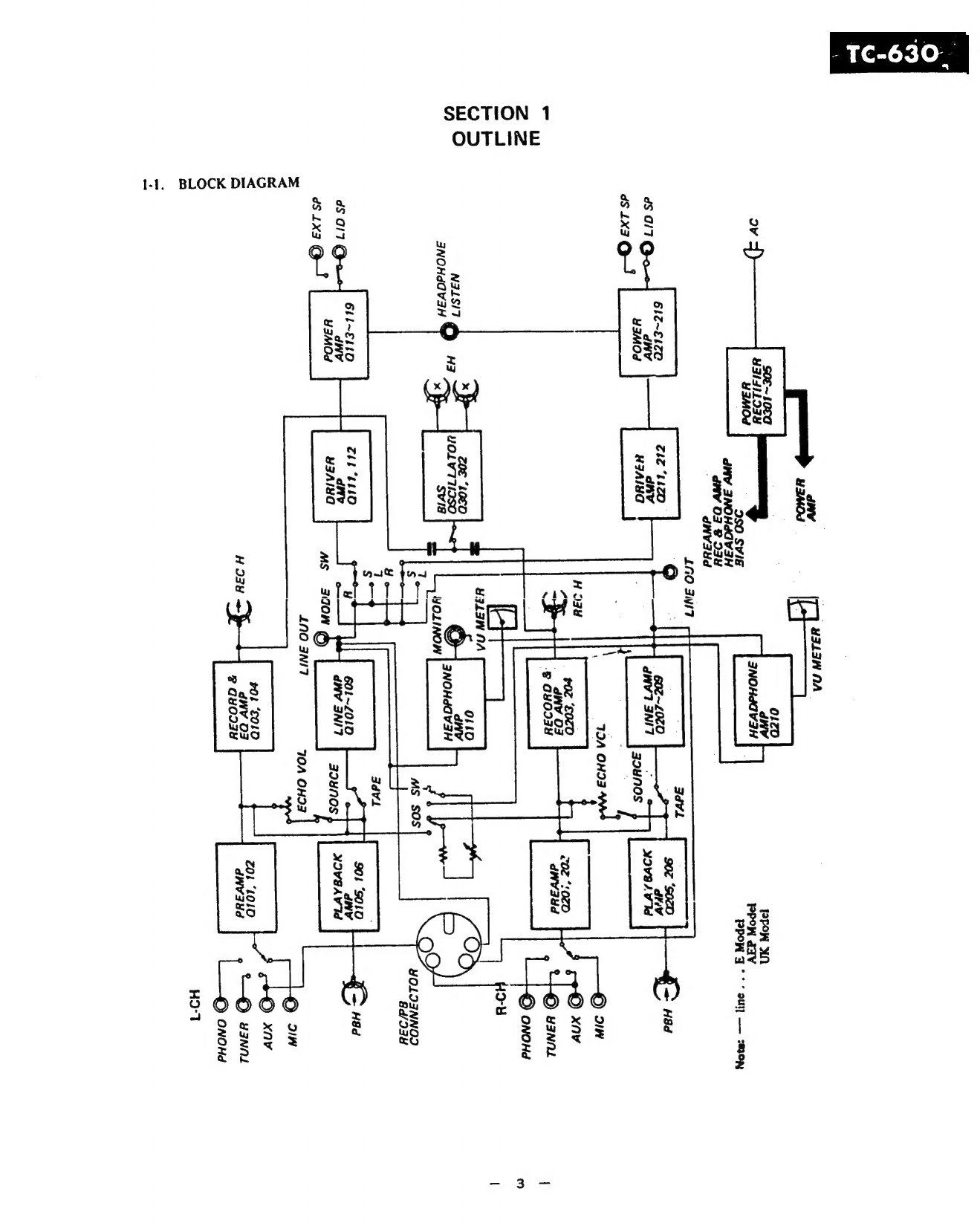
1
1.
OUTLINE
lehs.
Block:
Didgramy:
<<i3
sth
stedeicesteisid
shaven
atte
eden
erica Nitec
masiceeeat
3
122:
Cabinet:
Top
Views
ccs
secs
2c. ccc
cde
eeed
ao
at
Se
ae
4
1-3.
Cabinet
Side
Views
(AEP,
UK)
.0.....
ccc
cece
ceccenee
ener
centnereteeeeeees
4
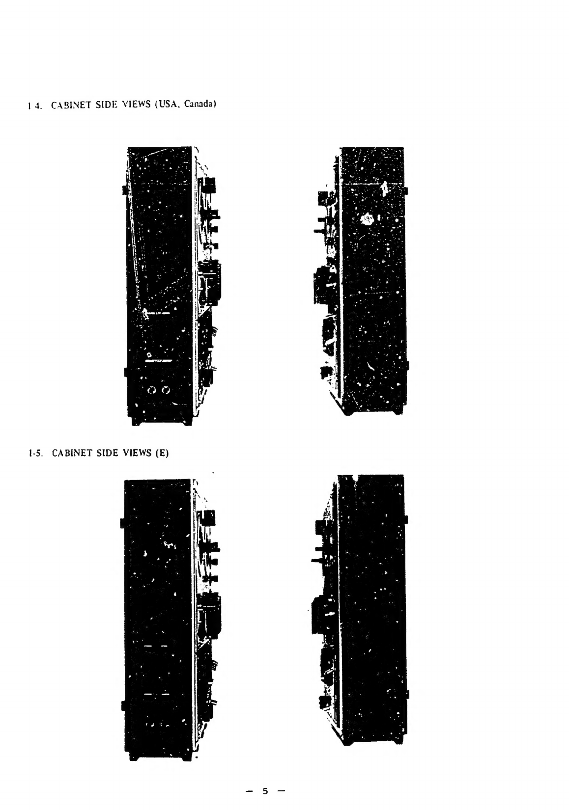
14.
Cabinet
Side
Views
(USA,
Canada)
0...
cccceceeeeeeeeeeeeeeeereee
5
1-5.
Cabinet
Side
View
(E)
oo...
ccecccesscccescccecesceseecsecceceessererssasaeecs
5
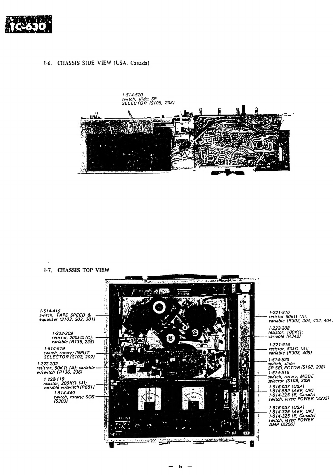
14.
Chassis
Side
Views
(USA,
Canada)
........cececcceccccecceeecee
sense
cseecesseees
6
1-72.
2Ghassis:
Tope
Mid
we
cok2sckes2ecenisahedansece
scsecsoseasavennes
pdeetbnetunctneetoisgochestonet
6
1-8.
Chassis
Bottom
View
(AEP,
UK)
oo...
.cccccccccccccccccceeseeceecesseeeeeceerees
7
1-9.
Chassis
Bottom
View
(E,
USA,
Canada)
0...
ccceeeseeeeterreeeeees
7
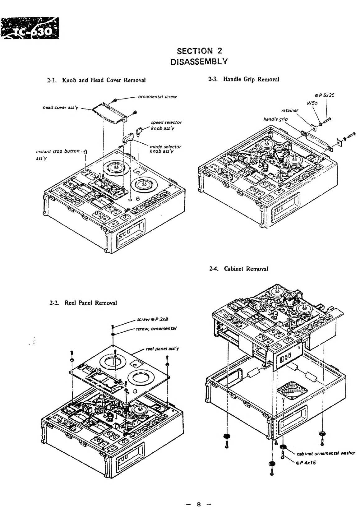
2.
DISASSEMBLY
i
ccckciteid
Seis
heen
atin
te
ieee
seenens
8
3.
MAINTENANCE:
2o.c22ccctescclndesstevicaciaideeek
ti
hnieniicn
ween
ins
9
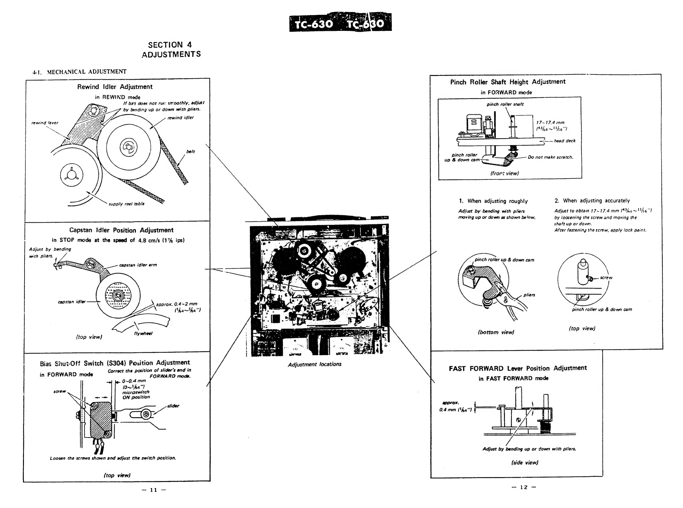
4.
ADJUSTMENTS
4-1.
Mechanical
Adjustments
..........
cc
ccccseeceecereeeeeeeeneeesererecessnneeaeeneereses
1]
4-2.
Adaptation
to
Different
Power
Line
Frequency
...........c.0.
cere
15
4-3.
Electrical
Adjustments
0.0...
cceccsseceeesssseecesseneeeeees
ceteaeenerenneneeners
16
5.
DIAGRAMS
S-1.
Wiring
Diagram
(E)
.0.........csescsssceeeccseceeeeseeteeceeeneeceeeceentserecsereenseees
19
5-2.
Wiring
Diagram
(USA,
Canada).......ccecceeeereesesseteectertertteeene
22
5-3.
Mounting
Diagrams
...........:cccsce
cscesseeeeeeceseseneneceenaneeeseeseateesaeenaereess
25
Record
Amp
Circuit
Board
—
Conductor
Side
-—
oe
25
Trap
&
Dummy
Coil
Circuit
Board
—
Conductor
Side
-.............
26
Bias
OSC
Circuit
Board
—
Conductor
Side
—
........
ce
eeeeseeeseeeees
25
Playback
Amp
Circuit
Board
—
Conductor
Side
—
«0...
eee
aT
Power
Amp
Circuit
Board
—
Conductor
Side
—
o....eeeeeeeeeeee
28
5-4.
Schematic
Diagram
...........
cece
ceeecseeceeeecee
seeseeseecneecennnnanaeenesereeeeees
29
$-5.
Level
Diagrams
..................csceeceesesceneeeecetsccesssneesaeeeneneneeneseceeceeeeaereess
32
6.
EXPLODED
VIEWS
6-1.
Control
Chassis
—
Top
View
—
..........ccccccesescesseeeecenneseseeessesonensooeeee
33
6-2.
Chassis
—
Bottom
View
—
.2...cceescececssecteccenessteesaeeceesesenecserensneeeee
34
6-3.
Amp
Chassis
—
Top
View
—
........ecsccccessrsececssreeeseeeseesessceeseesesesseses
35
6-4.
Head
Deck
—
Top
View
—
.........ccessceescssseserecereeceneencseceeercensceeecees
37
6-5.
Head
Deck
—
Top
View
—
Serial
No.
124,
701
and
later............
38
6-6.
Chassis
—
Top
View
—
......ccsccsscescesesseesessseseneeseneesessseeesseeseseeees
39
6-7.
Cabinet
—
Top
View
—
.........ccesccsssesseersececsrecessaceereeseseseeseesereeerees
41
6-8.
Speaker
Box
—
Top
View
—
....ccccsccccecersssseresseeesnesseesseerseeseeseneens
42
7,
ELECTRICAL
PARTS
LIST
oun...
ccc
secceceeeeensecseneeseeenaseceeeesesscneeeeee
43
8.
HARDWARE
oo...
.ccccc
cece
ceeccccscccceccensscecsenssceneesesssescecsenssenetseceeseseseranees
ree
47