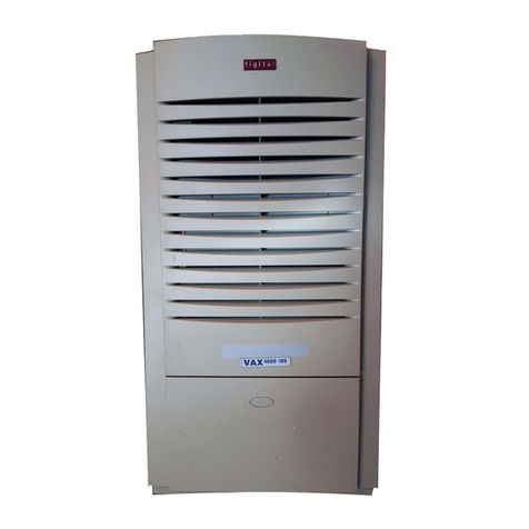
Digital Microsystems DMS-3/F User manual

Digital
Microsystems
un"
DMS-3/F
MANUAL
Version 1.0
Copyright
@1983,
Digital Microsystems

COPYRIGHT
All rights reserved.
No
part
of
this manual may be
reproduced
without
the
prior
written permission
of
Digital Microsystems, Inc.
Digital Microsystems, Inc.
17SS
Embarcadero, Oakland, CA 94606
(41S) S32-3686 TWX 910-366-3710
NOTICE
Digital Microsystems, Inc. reserves the right
to
make
improvements in the products described in this manual
at
any time,
without
notice.
TRADEMARKS
HiNet,
DMS-SOOO,
DMS-S016, OMS-S080, DMS-S086,
DMS-S087, DMS-3/F, and DMS-1S, are trademarks
of
Digital Microsystems, Inc. CP/M, and CP/M86, are
trademarks
of
Digital Research, Inc. MX-100 and
Graphtrax are trademarks
of
Epson,
Inc. Microline-83A
and Okigraph I are trademarks
of
,Okidata, Inc.
Manual written by:
Alan
H.
Stacy and
Bruce Hartford
Illustrations by:
Deborah Russell
Copyright
@1983,
Digital Microsystems, Inc.

FCC NOTICE
§ 15.818ClassAcomputingdevice:information
to
user.
Warning-This
equipmentgenerates, uses,
and
can radiate radio frequency energy and
if
not installed and used
in
accordance with
the instructions manual, may cause inter-
ference to radio communications.
It
has
been
tested
and
found tocomplywiththelimitsfor
a Class A computing device
pursuant
to
SubpartJ ofPart 15 of
FCC
Rules,which are
designed to provide reasonable protection
against
such
interferencewhenoperated
in
a
commercial environment. Operation of this
eqUipment
in
a residential area is likely to
cause interference
in
which case the user
at
his own expense
will
be required to take
whatever measures may be reqUired to cor-
rect the interference.


DMS-3/F
PREFACE
PREFACE
THE
MANUAL
Digital
Microsystems' Manuals
are
written
with
you,
the
user,
in
mind.
All
the
information
that
you need
to
know
about your
OMS
computer
and
the
HiNet Network
is
carefully
explained.
This manual
is
divided
into
eleven
sections.
They
are
organized
in
the
following
manner:
•
Section
1
(Introducing
the
Workstation)
will
introduce
you
to
the
particular
OMS
computer
that
you have and
explain
the
basic
procedures
for
setting
it
up
to
begin
work.
•
Section
2 (Using HiNet)
is
intended
for
new
computer
users
or
those
new
to
the
HiNet system.
It
contains
basic
information
about
files,
partitions,
network commands, and
other
material
regarding
the
workstations
and
the
HiNet
network.
•
Section
3
(CP/M
Environment)
covers
the
CP/M
operating
system.
•
Section
4 (Customizing)
will
explain
how
to
alter
the
operating
characteristics
of
the
workstation
to
suit
your
applications
and needs.
The
OMS
program
CUSTOMIZ
is
the
primary
means
of
adapting
your computer
to
your
specific
needs.
Release:
1
0/1/83
i

DMS-3/F
PREFACE.
•
Section
5 (Using
Printers)
discusses
how
to
use
printers
with
DMS
equipment and
the
HiNet
Network.
•
Section
6
(Hi
Net Master)
describes
the
DMS
equipment
that
can
be
used
to
run a HiNet
Network
(DMS-15
and
DMS-3/4
series).
It
also
explains
how
to
set
up
a HiNet Local Area
Network. This
section
is
not
included
in
manuals
for
equipement
that
are
not
HiNet
Masters.
•
Section
7 (Local Storage)
applies
to
DMS
computers
that
have
local
storage
capabilities
(e.g.,
Floppy Disks
or
Hard
Disks).
•
Section
8 (Graphics)
details
how
to
use
various
applications
packages
with
the
DMS-
5000's
graphic
capabilities.
(Not
included
in
the
DMS-15
or
DMS-3/F
manuals.)
•
Section
9 (Programs)
gives
some
further
explanations
of
various
software
packages
that
can be used
with
DMS
equipment and HiNet.
•
Section
10
(Electronic
Mail)
explains
how
to
use
DMS
electronic
mail
program.
This
system
lets
you send and
receive
messages
through your HiNet computer network.
•
Section
11
(Tele-Communications)
covers
the
use
of
Modems
and
other
forms
of
tele-communica-
tions
with
DMS
computers and HiNet.
•
The
Appendix
contains
a
list
of
the
most
common
error
messages and
their
meanings, and a
list
of
ESC
and
CTRL
codes
that
you
may
need
to
Release:1
0/1/83
.
ii

OMS-3/F
PREFACE
know
to
configure
your
OMS
equipment
to
printers
and word
processing
programs.
MANUAL
CONVENTIONS.
In
the
text
of
this
manual,
prompts
and
other
messages
that
are
displayed
on
the
CRT
screen
by
the
computer
will
be
shown
in
a
different
typeface,
while
characters
and commands
that
you,
the
user,
enter
through
the
keyboard
will
be
both
boldfaced
and
underlined
in
the
screen
typeface.
Boldfaced
and/or
underlined
comments
in
the
normal
text
typeface
are
used
to
accent
important
points
in
this
manual.
Because
computer
programs
and
hardware
are
constantly
being
imprOVed and
updated,a
'version
number'
almost
always
follows
the
name
of
the
product.
This
number (sometimes
called
'revision
number')
is
used
to
identify
the
version
and
capabilities
of
the
product.
Since
these
numbers
are
changed
every
time
a
product
is
upgraded
this
manual
will
indicate
them
by
the
letter
x
in
screen
depictions.
Thus,
in
Version
x.x
the
'x.x'
would
simply
represent
some number
that
may
vary
from
unit
to
unit.
Often
a
version
number
will
include
a
release
date.
In
this
manual
these
release
dates
are
indicated
by mm/dd/yy
(for
month/day/year).
Release:
1
0/1/83
iii

DMS-3/F
PREFACE
To
bring
to
your
attention
important
points
that
might
otherwise
be
easily
passed over,
this
manual
will
use
three
different·
'levels'
of
NOTE
headings.
NOTE---
These
are
details
that
you should
know
in
order
to
use
the
equipment. They
are
points
that
will
help
you
to
avoid problems
as
you use
the
computer.
Here
is
a
point
which you must pay
close
attention
to
in
order
for
the
system
to
work.
It
should
catch
your eye
if
you
are
having a
problem and
are
going back
to
the
manual
for
information.
WARNIR;!-
WATCH
IT! This
indicates
that
something
could
go
very
wrong
if
you
don't
pay
close
attention.
Always heed
these
warnings.
PAR'!'
NOM3ERS
If
you need a
specific
part
that
is
referred
to
in
this
manual, you should
contact
your
DMS
Dealer
or
Digital
Microsystems
directly.
Describe what you need
or
use
the
part
name
given
in
the
manual.
Release:
10/1/83
iv

DMS-3/F
PREFACE
FEEDBACK FROM YOU.
Digital
Microsystems would
like
this
manual
to
be
as
clear
and
informative
as
possible.
If
you encounter any problems
in
using
this
manual,
or
have any comments or
suggestions,
please
let
us
know.
We
have included a Customer Feedback
form
for
you
to
use,
and comments
are
welcome
from you
at
any
time.
(All comments and sugges-
tions
become
the
property
of
Digital
Micro-
systems.)
HINET.
HiNet
is
a Local Area Network. A
local
area
network
is
a
varied
group
of
computers which
communicate
with
each
other
via
a
cable
that
goes from machine
to
machine.
The
great
advantage
of
this
system
is
that
many
people
can
work
together,
storing
their
work
in
central
Hard Disk
Memory
units,
and
sharing
many
kinds
of
computer
resources
(hardware,
printers,
software,
databases,
etc.).
See
section
2.
If
desired,
a
printer
or
other
device
can
also
be
connected
separately
to
an
individual
workstation
(see
section
5.4).
Release:1
0/1/83
v


TABLE
OF
00N'.l'mTS
1.0
IN'I'RODOC'TION
'10
THE
Do1S-3/F
1.1
0'VERVIJ!J'l
• • • • • • • •
1.2
SETl'It13
UP
THE
DHS-3/F
••
THE
CRT
SCREEN. • •
LINE
VOLTAGE
SWITCH
•
RESET
AND
INTERRUPT
• •
• 1- 1
• 1-1
••
1-2
1-4
• •
1-5
1.3
TORNIt13
ON
THE
IHS-3/F
•
1-5
USING
AS
A
STAND-ALONE
COMPUTER.
1-5
USING
AS
A
HINET
WORKSTATION
•••
1-7
1.4
THE
1.4.1
1.4.2
1.4.3
KEYBOARD
••••
NUMERIC
PAD
• •
FUNCTION
KEYS
• •
MAIN
SECTION. •
1.5
DMS-3/F
PORTS. •
1
.6
MlUN'l'.IH\tCE • • • . . .. . . ..
•
••
1-7
•
••
1-8
•
1-9
•
1-11
•
••
1-16
•
••
1-17
,
2.0
USIt13
THE
WORKSTATION
WITH
HINET
2.1
INTRODUCTION.............
2- 1
2.2
BEFORE STARTING
2.3
THE CURSOR
•••
2.4
LOGGING
ON
•
2.5
THE PROMPT •
2-1
2-2
• •
2-3
2-5

2.6
USIt«;
<llMPO'.rER
aHmlI>S.
• • • • • • •
2-5
CANCELLING
&
CDRROCTING
CDMMANDS.
• •
2-6
2.7
THE
TYPE
AHEAD
BUFFER. • • • •
~
• • •
2-
7
2.8
LOGGING
OFF.
• • • • • • • • • •
2-7
2.9
FILES
AR> PARrITIONS, OVERVIDf. • • •
2-8
2.10
PILES.
• • • • • • • • • • • • • • •
2-13
2.
1O.1
FILE
NAMES
• • • • • • • • • • •
2-
13
2.10.2
FILE
TYPE
IDENTIFIERS
••••••
2-13
2.
10
.3
FORBIDDEN
CHARACTERS
• • • • • •
2-14
2.
1
0.4
FILENAME
WILDCARD
SYMBOLS.
• • •
2-1
5
2.11
PARl'ITIONS. •
.•
• • • • • • • • • • •
2-16
2.11.1
PARTITION
NAMES
•••••••••
2-16
2.11
.2
DIRNET
(DIRECTORY
NETWORK)
• • •
2-16
2.11.3
PARTITION
SIZES
•••••••••
2-17
2.11.4
PARTITION
DEFAULT
ASSIGNMENTS
••
2-18
2.11.5
ASSIGN
CDMMAND
•••••••••
2-19
ASSIGNING
DRIVES
TO
FLOPPY
DISKS
2-21
2.11.6
PASSIDRDS
••••••••••••
2-23
2.12
USIt«;
PAR"l'ITIONS
All)
PILES.
• • • • •
2-24
2.12.1
CHANGING
DRIVES
AND
PARTITIONS.
2-24
2.12.2
FILES,
COMMANDS,
& PARTITIONS
••
2-25
2.12.3
PARTITION SIZES &
DIRECTORY
SPACE2-28
.
2.13
SHARIt«; PARTITIONS. • • • • • • • • •
2-29
2.13.1
HIOOS
•••••••••••••
2-30
2.13.2
NETLOCK
••••••••••••
2-32
2.13.3
USING
TWO
STATIONS
AT
ONCE
• • •
2-34
2.14
'l'HE
WHO
COMMAHD
•••••••••••
2-35

2.14.1
WHO
HIST
COMMAND.
•
••••••
2-37
2.15
RES
ET.
•
••••••••••••••
2-38
3.1
INTRODUCTION.
•••
3-1
3.2
DIR
(Directory).
• • •
3-1
3.3
so
(Super
Directory).
•
3-3
3.4
REN
(Renaming
Files).
•
3-5
3.5
ERA
(Erasing
Files).
• •
3-6
3.6
PIP
(Copying
and
Transferring
Files)
•
3-7
3.6.1
COPYING
FILES.
• • • • •
3-7
3.6.2
COPYING
MULTIPLE
FILES
••••••
3-10
3.6.3
VERIFYING
PIP
COPIES. • •
••
3-11
3.6.4
COPYING
PROGRAM
FILES
••••••
3-11
3.6.5
CHANGING
FILE
NAMES
WITH
PIP
•••
3-12
3.6.6
COMBINING
FILES
WITH
PIP
•••••
3-13
3.6.7
PIPPING FILES
TO
OTHER
PARTITIONS
3-14
3.7
TYPE
(To
See
a
File's
Contents)
••••
3-15
3.8
CTRL
P
(Typing
to
Paper)
•••••••
3-17
3.9
usnx;
SUBMIT
FILES
ON
HINE'!'. • • • • • 3-1 8
4.0
CUSTOMIZING
4.1
INTRODOCTiON
•••••••••••••
4-1
4.1.1
SCREEN
ATTRIBUTES.
•
4-2
4.1.2
SPOCIAL
FUNCTION
KEYS
••••••
4-2

4.1.3
TERMINAL
EMULATIONS
•••••••
4-3
4.1.4
CHARACTER
SETS
•••••••••
4-3
4.1.5
KEYBOARD
RE-ARRANGEMENT
•••••
4-3
4.
1
.6
USING THIS
PART
OF
THE
MANUAL
• •
4-4
4.2
USIt«;
aJS'lOfiZ
• • • • • • • •
4-6
4.2.1
INTRODUCTION
••••••••••
4-6
4.2.2
USING SETTINGS
FILES.
• • •
4-7
4.2.3
CUSTOMI
Z
MENU
SCREEN
• •
4-
7
STARTING
WIlli
CUSTOMIZ. • •
4-7
MAIN
MENU
COLUMN
••••
• • • •
4-1
0
SUB-MENUS
• • • • • • • • • •
4-1
0
NO
CHANGES
• • • • • • • • • • •
4-
11
CURRENT
SETTINGS
COLUMN
•••••
4-11
SAVE
SETTINGS.
• • • • • •
4-12
OVERWRITE
• • • • • • • • • • • •
4-13
RECALL
SETTINGS
• • • • • • •
4-14
LEAVING
CUSTOMIZ
••••••••
4-17
UPDATING
A SETTINGS
FILE.
•
4-18
4.2.4
CUSTOMIZ
AND
HINET LOGIN. •
4-19
4.2.5
CUSTOMIZ
ON
THE
DMS-5000.
••
4-20
4.2.6
SETTINGS
FILE
INTERCHANGEABILITY.
4-20
MANAGER
IDDE. • • • • • •
4-21
4.3
~
BRIQI'l'NESS. • •
4-22
4.4
SCREEN
TYPE. • • • •
4-24
4.5
Ql)()SIt«;
A alROOR
TYPE
(DMS-5000
only)
4-27
4.6
SCREEN
SIZE
(DMS-SOOO
only)
.... .
4-28
4.7
SPB:IAL
FOtCrION
KEYS
••
• • • • • •
4-31
4.7.1
DEFINING/ERASING A
FUNCTION
KEY
•
4-31
CREATE/ERASE. • • • • • • • • • •
4-32
EDITING A SPECIAL
FUNCTION
KEY.
•
4-33
CORRECTING
ERRORS
• • • • • • • •
4-34

THE
@
AND
COMMAND
KEYS
••••••
4-34
NESTING
FUNCTION
KEYS
• • • • 4-35
CHARACTER
LIMIT"
• • • • • 4-36
4.7.2
DISPLAY
ALL
KEYS
••
• • • • 4-36
4.7.3
READ
IN
PRESENT
SETTINGS.
• • 4-37
4.7.4
AVAILABLE
SPEX:!IAL
FUNCTION
KEYS
• 4-37
4.7.5
SPEX:!IAL
FUNCTION
KEYS
••••••
4-40
4.7.6
I~ER
PAD
KEYS
•••••••••
4-40
4.7.7
DMS-5000
DEFAULT
SETTINGS
••••
4-41
4.7.8
TEMPORARY
S.F.K.s
••••••••
4-42
4.7.9
SOME
IDEAS
FOR
FUNCTION
KEYS
•••
4-43
4.8
~NAL
~IOHS.
• • • • • • • • • 4-45
4.8.1
REQUIREMENTS
••••••••••
4-45
4.8.2
TERMINAL
EMULATION
WITH
CUSTOMIZ.
4-45
4.8.3
EMULATION
WITHOUT
CUSTOMIZ.
• 4-47
4.9
CHARACTER
SBmS
• • • • • • • • • • 4-48
4.9.
1
SELEX:!TING
A
CHARACTER
SET
• • • • 4-48
4.9.2
THE
LANGUAGE
SETS
• • • • • •
4-51
SPANISH
CHARACTER
SET
• • • • 4-52
4.9.3
USER
DEFINED
CHARACTER
SET
••••
4-52
4
.9.4
CREATING
A
CHARACTER
SET
• • • • 4-53
STARTING
A
CHARACTER
SET.
• • • • 4-53
DEFINING
CHARACTERS
• • • • • 4-54
THE
CHARACTER
GRID
••••••••
4-55
CHARACTER
SIZE. • • • • • • • • • 4-58
4.9.5
CHARACTER
SETS
&
PRINTERS
••
4-58
DMS-5000
••••••••
• 4-59
DMS-3/F
&
DMS-15
•••••••
• 4-60
USER
DEFINED
CHARACTERS
• • • • • • • 4-60
SCREEN
DUMP
• • • • • • • • •
4-61
4.10
KEY:BOARD
LA!OOT
• • • • • •
••
4-62
4.10.1
CHOOSING
A
KEYBOARD
•••••••
4-62
THE
TYPIST'S
KEYBOARD
• • • • • • 4-65
4.10.2
CREATING
YOUR
OWN
KEYBOARD
•••
4-65

CHARACTERS
• • • • • • •
4-67
KEYBOARD
DIAGRAM
• • • •
4-67
REASSIGNING
KEYS
• • • • • • • •
4-68
SAVING
YOUR
KEYBOARD
• • • •
4-69
STARTING
OVER
• • • • • • •
4-69
ABANDONING
YOUR
IDRK
• • • • • •
4-70
COMMAND
KEYS
WARNING
• • • •
4-70
4.10.3
OiANGING
THE
KEYCAPS
• • 4-71
4.11
aJS'roMIZ
SYSTm
RlQJIRDBftS.
4.11.1
CRT.VERSIONS •
.;
••••
4.
11
.2
KEYBOARD
VERSIONS
•••
4.11.3
OBTAINING
VERSION
NUMBERS
4.11.4
PROGRAM
FILES
•••
4.11.5
SAVING
DISK
SPACE
••••••
4.12
KE!BOARD
DIAGRAMS
• • • • • •
5.0
USIt«;
PRINTERS
•
4-73
• •
4-73
• •
4-73
4-74
•
4"':74
• •
4-75
••
4-76
5.1 INTRODUCTION.
••••••••••••
5-1
5.1.1
LINKING
TO
A PRINTER
•••••••
5-1
5.1.2
SENDING
TEXT
TO
A
PRINTER.
•
5-2
5.2
SPOOL PRINTER. • • • • • • • • • • • •
5-4
5.2.1
SENDING
TEXT
TO
THE
SPOOLER • • •
5-5
5.2.2
SPOOLER
MANUAL
MODE
•••••••
5-8
S.2.3
SPOOLER
COMMANDS.
• • • • • • • •
5-11
5.3
DIRECT
CONNECT
PRINTERS. • • • • • • •
5-
12
5.3.1
SERIAL PRINTERS • • • • • • • • •
5-13
5.3.2PARALLEL PRINTERS
••••••••
5-15
5.4
STOPPING
THE
PRINTER • • • • • • • • •
5-1
5
5.5
SE'.l"'.l"IM;
'l1IE
BAUD
RATE.
• • • • • • • •
5-16

5.6
INTERt"ACItC
PRINTERS
• • • • • • • • • 5-1 8
5.6.1
PROTOCOLS
••••••••••••
5-19
HARDWARE
HANDSHAKING.
• •
5-20
X/ON
X/OFF.
• • • • • • • • •
5-
20
ETX/ACK
• • • • • • • • 5-21
5.6.2
JUMPER
BLOCKS
• • • • • • 5-21
MAKING
JUMPER
BLOCKS.
•
5-22
DIAGRAMS
OF
roPULAR
JUMPER
BLOCKS
5-24
MODEM
JUMPER
BLOCK.
• • • • • • •
5-26
5.6.7
INSTALLING
JUMPER
BLOCKS.
• •
5-27
SERIAL
PORT
I/O
BOARD
• • • • • •
5-28
6.0
HINE'l'
MASTER
7.0
LOCAL
STORAGE
7.1
FLOPP!'
DISKE'I"l'ES
• •
~
• • • • 7-1
7.
1.1
HANDLING
FLOPPY
DISKETTES
• •
7-2
7.1.2
INSERTING
FLOPPY
DISKETTES
••••
7-3
CHANGING
DISKETTES.
• • • • •
7-4
7.1.4
DISK
DRIVE
DESIGNATORS
••••••
7-5
7.1.4
WRITE
PROTECT
NOTCH.
• • • •
7-6
7.1.5
STAT--PROTECTING
FILES
AND
DISKS.
7-7
7.2
FOBMATTItC
A
FLOPPY
DISKE'I-rE
• • • • •
7-8
7.2.1
USING
FORMATS
~
•••••••••
7-9
7
.3
~Pi'!tC
'l'HE
CP/M
SYS'ftM
"l"RACKS
7-10
USING
SYSGEN.
• • • • • • • • • 7-11
7.4
OOPi'!tC
FLOPPY
DISKE'rl'ES • • • • • • •
7-13
8.0
GRAPHICS
9.0
MIS=. UTILITIES
9.
1
TIME
&
SE'l'TIME
• • • • • • • • • • • •
9-
1

10.0
EI:.JCl'RONIC
MAIL
11.0
TELE-aHIlNICATIONS
APPDI>IX
A-ERR)R
MESSAGES
APPEHlIX
B-ES:
AtI)
crRL
CXDES
APPDI>IX C--cABINET DISASSD4BLY &
JUMPER
PINS
SECTION
2
5
5
7
7
A/C
A/C
APPEHlIX
J>.:-PARAI.I.EL PRINTER CABLE
IlmEX
LIST
OF
DIAGRAMS
DESCRIPTION
Front
of
DMS-3/F
cabinet
Rear
of
DMS-3/F
cabinet
Keyboard
layout
Partitions
illustration
Jumper block diagrams
Input/Output
board
Inserting
Floppy
Diskette
Floppy
Diskette
Write
Protect
Notch
DMS-3/F
Cabinet
Disassembly
Jumper
pins
PAGE
2-12
5-24
5-28
7-3
7-6
A/C-2
A/C-6

LEG RELEASE
//
FLOPPY
DISKETTE
DRIVE
o
DIAGRAM
1-1
FLOPPY
DISKETTE
DRIVE

Table of contents

