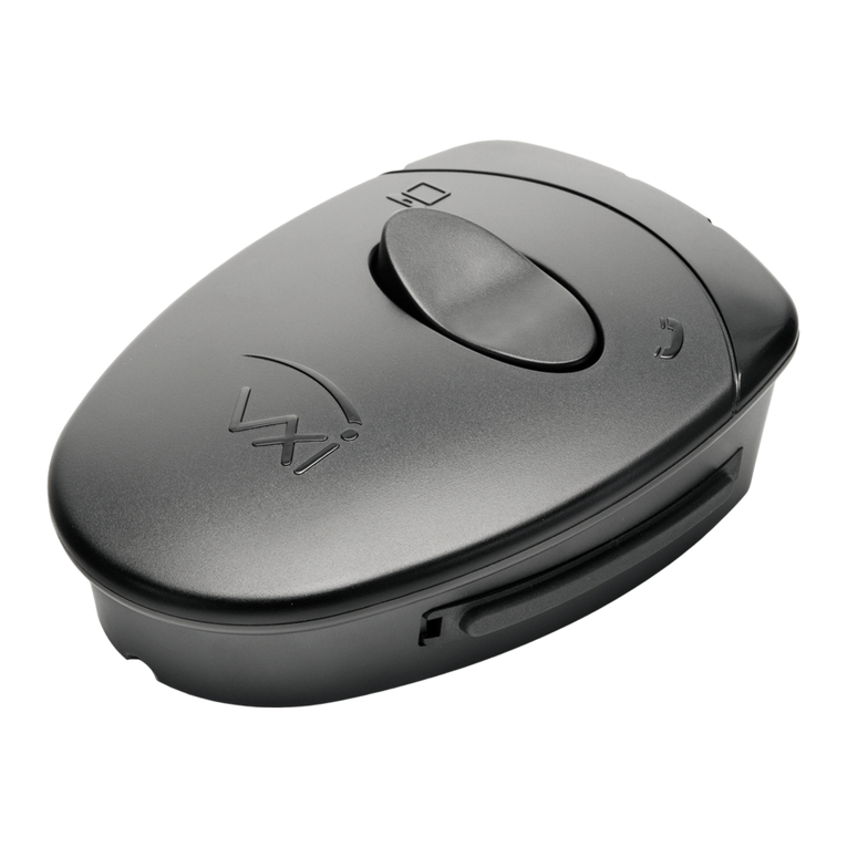
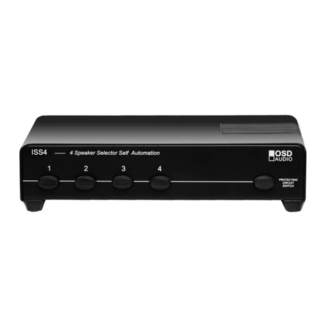
Digital Products Ring-it! User manual

BY^W9d Telephone Line Simulator Page 1 © 1995-1999
BY^W9d
™
Quick Reference Guide
Digital Products Company, USA
http://www.digitalproductsco.com
RING-IT’s LED readout is used to indicate Mode, Cycle Time, and dialed digit information. Its decimal
point is illuminated only when the mode or cycle time is shown; a decoded DTMF (Dual Tone Multi-
Frequency) digit is shown as a value without the decimal point.
RING-IThas five different operational modes that can be invoked through one of the front panel mounted
push switches. The LED readout displays the current mode that is in use. The five modes can be
invoked by pressing the MODE switch; the active mode is shown in the LED display. The modes are
summarized as follows (the bracketed value indicates the corresponding LED display):
[n.] Normal Ring Mode
[A.] Automatic Ring Mode
[b.] Beep Tone Mode
[c.] Cycle Ring Test Mode
[d.] Dumb Mode
[n] Normal Mode
The
normal
mode is used when you want standard telephone system emulation. When you take the
MAIN line’s (line 1) phone off-hook, a dial tone is heard. If you do nothing for twenty seconds then a
“reorder” sound is heard. If you tone dial any seven digit phone number then the Test line’s (line 2)
phone will start to ring. When the TEST line answers the front panel CONNECT LED will light up.
While you press the DTMF keys of your phone, the corresponding digit will appear in the LED display
for up to two seconds. The “L” tone is shown as “A”, and the “#” key is shown as “P.”
If you attempt to ring the TEST line and it is off-hook, then a busy signal will be heard. Please note that
because it is a one-way device, the TEST line can not be used to ring the MAIN line.
There are some shortcuts in the
normal
mode that can be used to ring the TEST line. For example,
pressing the MAIN phone's DTMF “L” key will immediately start the ring request. The front panel RING
switch will also start the ring cycle, which can be used if the MAIN line's phone is not DTMF compatible.
The
normal
mode is perfect for demonstrating telephone equipment such as answering machines, Fax
systems, Voice mail, modems, and more! Because the standard call progress audio tones are heard,
your demonstration will appear more natural to your audience and equipment.
[A] Automatic Ring Mode
The
automatic
ring mode is similar to the
normal
mode except that ringing begins immediately after the
MAIN line’s phone is answered. This operation is sometimes called a “Ring-Down line” by phone system
manufacturers. If either line is off hook when the other is answered, the two lines will be automatically
connected together.

BY^W9d Telephone Line Simulator Page 2 © 1995-1999
The
automatic
mode, besides being used to test phone equipment, is also perfect for use as a front entry
intercom for home or office use. Place a phone near you and one near your entry. Be sure to post a
note near the entry phone that instructs your visitors to “lift the receiver for assistance.”
[d] Dumb Mode
The
dumb
mode provides a silent talk path and allows a manual ring. You will not hear any call progress
tones; however you can converse normally.
TEST line ringing is controlled by using the RING switch or the MAIN phone's “L” key. The ring signal will
follow the keypresses. Unlike the other modes, they do not continue to ring when the keys are released.
Whenever the TEST line is taken off hook the two lines will be automatically connected together.
The
dumb
mode is perfect for testing the basic operation of equipment. Because you can control the
duty cycle (cadence) of the ring signal, non-standard equipment can be tested for ring operation.
[b] Beep Tone Mode
The
beep tone
mode is specially designed for cycle testing answering machines and other types of
telephone equipment. This mode does not start until the Ring button or DTMF “*” key is pressed.
It is not necessary to have the MAIN line’s phone off-hook during the
beep
mode. Whenever the TEST
line is answered a series of repeating test tones are sent to the telephone equipment being tested.
During the beep mode the TEST line automatically rings after a short delay (time delay is adjustable at
rear of unit). If the line is answered, staggered beep tones are played. These tones have been designed
to keep a voice controlled answering machine from hanging up. The ring-up cycle repeats (after an
adjustable delay) until it is canceled by pressing the MODE switch).
For example, if the delay control (on the rear panel) is set for thirty seconds, the device being tested will
be rung-up thirty seconds after the last answer/disconnect cycle. The test tones will be played as long
as the TEST line is off-hook. If the TEST line goes on-hook, the delay cycle starts up again.
[c] Cycle Mode
The
cycle
mode provides most of the features of the
beep
mode except that the beep tones are not
played and a phone must be plugged into the MAIN line. To start the cycle you must pick up the phone
MAIN line telephone. If either line is off hook when the other is picked up, the two lines will be
automatically connected together.
When the TEST line answers, your conversation may begin. If it hangs up and the MAIN phone remains
off-hook, the TEST line is automatically rung up after the delay time. This cycle repeats until the MAIN
phone is hung up.
Beep and Cycle Mode Operation
To use the
Beep
or
Cycle
modes with the delay feature, connect an answering machine or telephone to
the TEST line. If you are using the cycle mode be sure to also install a phone in the MAIN line jack. Start
line ringing by lifting the MAIN line’s phone off-hook (cycle mode) or pressing the RING switch (beep
mode).

BY^W9d Telephone Line Simulator Page 3 © 1995-1999
While the TEST line is ringing, you can change the delay (adjustable at rear of unit) from one to ninety
seconds (1-9) by viewing the LED display. If the delay cycle has already started (as seen by the chasing
LED pattern), you can press and hold the RING switch to review the delay count setting.
When the TEST line is answered, a series of beeps will be generated that will make most voice operated
(VOX) answering systems stay on the line (if they are operating correctly). If you want to force the
answering system to periodically hang up, just use their VOX time limit switch.
Keep the MAIN line off-hook if using the
cycle
mode. After the answering machine (or telephone) hangs
up it will be cycled on again every 10-90 seconds, depending on the delay pot's position. At any time
you can cancel the
beep
or
cycle
modes by pressing the MODE switch.
J3 Power-On Mode Jumper
You can set the default (power-on) operating mode for either [N]ormal or [A]utomatic by the J3 jumper
setting. The J3 jumper block is located on the circuit board and is easily accessed by removing the two
case screws on the unit’s bottom side. Once inside the unit, locate the jumper, labeled J3, and set per
table 1. Typical phone line applications (ring after dialing) require the [N]ormal mode(J3 removed).
J4 CPC Jumper
Whenever the MAIN line disconnects, a momentary interruption of the phone line current occurs to
simulate the central office’s
Calling Party Control
(CPC) feature. You can turn the CPC feature On or
Off by the J4 jumper setting. The J4 jumper block is located on the circuit board and is easily accessed
by removing the two screws that hold the case together. Once inside the unit, locate the jumper, labeled
J4, and set per table 1. We recommend that you leave the jumper installed (CPC on).
DESCRIPTION JUMPER SETTING
Default = [N]ormal J3 Removed
Default = [A]utomatic J3 Installed
CPC = Off J4 Removed
CPC = On J4 Installed
TABLE 1
General Test and Check-out
If you suspect that your RING-ITunit is not performing correctly, then follow these simple steps to verify
correct operation:
Step 1. Disconnect any telephone equipment plugged into the phone jacks.
Step 2. Remove the J3 power-up mode configuration jumper connector. Set the time delay
adjustment (accessible at rear of unit) to about mid-way.

BY^W9d Telephone Line Simulator Page 4 © 1995-1999
Never plug RING-ITdirectly into a phone line. This unit was designed to
connect to phone equipment only and it WILL BE DAMAGED by the
voltages present on an active phone line!
Step 3. Apply AC power and verify that the LED display shows “r.” (reset) for a moment, then
shows “n.” (Normal mode). Press the MODE switch and verify that it can be cycled through
the five different modes (n,A,b,c,d).
Step 4. Remove power and install the J3 configuration jumper. Turn on AC power and verify that
the LED display shows “r.” for a moment then shows “A.” (Auto mode).
Step 5. Using the front panel MODE button, set the unit to Normal mode (“n.”). Connect a standard
telephone to the MAIN line’s (main) modular phone jack.
Step 6. Pick up the MAIN line and verify that dial tone can be heard. If you are using a DTMF
phone then dial a digit and verify that the dial tone stops and the digit is shown in the LED
display.
Step 7. Hang up the phone, then lift the handset again. Verify that dial tone returns. Press the
RING switch once and verify that a ringing sound can be heard in the telephone handset
(it should sound like an authentic ring signal). Pressing the RING switch again or hanging
up the phone up will terminate the ring sound and return dial tone.
Step 8. Plug a second telephone into the TEST line jack. Pick up the MAIN line’s phone and again
press the RING switch. Verify that the phone's bell on the TEST line is ringing with a North
American type ring cadence (two seconds on, four seconds off).
Step 9. Try the remaining operational modes. For example, set the mode to “A” (Auto) to have the
TEST line ring whenever the MAIN line is lifted off-hook.
For more Information please contact
*OMOZGR6XUJ[IZY
&RPSDQ\
134 Windstar Circle
Folsom, CA 95630
Tel 916-985-7219
Fax 916-985-8460
E-mail [email protected]
http://www.digitalproductsco.com
Table of contents
Other Digital Products Switch manuals
Popular Switch manuals by other brands
KVMSwitchTech
KVMSwitchTech KVMSWR-2X16IP installation guide
Kramer
Kramer VS-41HDCP user manual
Siemens
Siemens SIMATIC NET RUGGEDCOM RS920L installation manual
Covid
Covid SB3M-A110 user manual

Warner Electric
Warner Electric 1100-42 installation instructions
Proscend
Proscend 850G-14I Quick installation guide
