Specifications subject to change without notice
© Digital View Ltd – Doc Ver 3.01: 13 April, 2016 Page
15 of 58
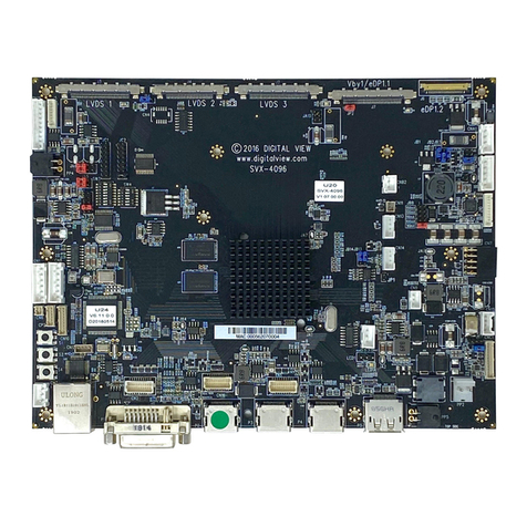
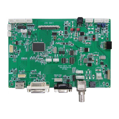
J3 LVDS panel signal output 2 JAE FI-RE51S-HF (Matching type : FI-RE51HL)
J4 Display port output for panel
connection
I-PEX 20455-030E-12 (Matching type : I-PEX 20454-030T)
J5 Panel power output for Disport port
interface panel use.
Molex 53261-0871 (Matching type : Molex 51021-0800)
J6 Reserved for Digital interface for SDI /
Video mux board (AVD-1000)
connector. (This connector function is
not implemented yet)
DIL Header 25x2, 1.27x2.54 SMT
P1 VGA DB-15 way high density 3 row
P2 DVI-D DVI-D connector
P3 HDMI HDMI connector
P4 Displayport Display port connector
PP2 Power input (alternative) DC power Molex 2 pin 0.156” pitch
PP4 External panel power input Molex 43045-0400 compatible
(Matching connector type : Molex 43025-0400 compatible)
(Matching power cable : P/N 426013700-3)
PP5 Power input Molex 43650-0200 compatible
(Matching connector type : Molex 43645-
(Matching power cable : P/N 426013800-3)
SW3 Panel selection 8-way DIP Switch
SW4 Function selection 6-way DIP Switch
Summary: Jumpers setting
Ref
Purpose Note
JA2 On board +3.3V logic power enable 1-2 & 3-4 closed, factory set, do not remove
JA3 Panel power voltage select
CAUTION: Incorrect setting can damage
panel
See panel voltage setting table 1
JA5 Panel power voltage select
CAUTION: Incorrect setting will cause panel
damage
See panel voltage setting table 1
JA6 Panel power voltage select
CAUTION: Incorrect setting will cause panel
damage
See panel voltage setting table 1
JB1 Backlight brightness voltage range 1-2 closed = 5V max
2-3 closed = 3.3V max
JB2 Backlight inverter on/off control – signal level 2-3 = On/Off control signal ‘High’ = +5V
1-2 = On/Off control signal ‘High’ = +3.3V
Open = On/Off control signal ‘High’ = Open collector
CAUTION: Incorrect setting can damage inverter.
JB3 Backlight inverter on/off control – polarity 1-2 = control signal ‘high’ = CCFT ON
2-3 = control signal ‘low’ = CCFT ON
JB4 GPIO pins voltage selection 1-2 = 3.3V
2-3 = 5V
JB5 Backlight control type selection 1-2 = VR/Digital switch mount control
3-4 = Analog backlight brightness - voltage range 0~5V
5-6 = PWM (Pulse Width Modulation) brightness
JB6 Maximum LED backlight current selection 1-2 = 150mA
3-4 = 120mA
JB7 Backlight control voltage on CNB1 pin 4
(Function when JB5 sets 1-2 closed)
Open = For OSD switch mount control (Default)
1-2 = 0V
2-3 = 3.3V / 5V controlled by JB1
JB9 On board LED backlight driver function Open = Disable
Closed = Enable
JC1 Custom configuration Default Open
JC2 Custom configuration Position 1 : Enable J3 – pin 16 (OP1) controlled by JB4
Position 2 : Enable J3 – pin 17 (OP2) controlled by JB4
Position 3 : Enable J3 – pin 18 (OP3) controlled by JB4
Position 4 : Enable J3 – pin 19 (OP4) controlled by JB4
JP4 Custom configuration Default Open
JP6 Input power control Short = External switch control
Open = Switch mount control
JP9 Factory use Default Open
S1 Reset button (IP-60) Tact switch button
S2 Reserved Tact switch button
S4 Config menu function Tact switch button
SW3 Panel & function selection See table 2
SW4 Panel & function selection See table 3
Downloaded from Arrow.com.Downloaded from Arrow.com.Downloaded from Arrow.com.Downloaded from Arrow.com.Downloaded from Arrow.com.Downloaded from Arrow.com.Downloaded from Arrow.com.Downloaded from Arrow.com.Downloaded from Arrow.com.Downloaded from Arrow.com.Downloaded from Arrow.com.Downloaded from Arrow.com.Downloaded from Arrow.com.Downloaded from Arrow.com.Downloaded from Arrow.com.


