DIEGON AP80 User manual

Manual AP80
Display Controller
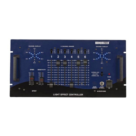
•8 Digit display in DIN-enclosure 144 X 72 mm
•Supply voltage 10 – 35V DC
•All in- and outputs optically isolated
•Input for absolute SSI encoders, incremental en-
coders, parallel encoders and Start/Stop sensors
•CAN-bus, RS232, RS422/RS485
•6 Digital inputs and 9 digital outputs
•24 Programmable cams / 9 outputs
•48 Programmable nominal values
•Dynamic cam-adjustment (cycletime 250µ
µµ
µS)
•Programmable analog output (16 bit)
•Linearization function
•Datamodule for 24 in- and 24 outputs
•Datamodule for 32 (tri-state) outputs

Manual AP80
2016 V02. For software version V6.03. Subject to change without notice.
2
Table of contents
1
Introduction................................................................................................6
1.1
G
ENERAL
.................................................................................................................................6
1.2
I
MPORTANT INFORMATION
......................................................................................................7
1.3
EMC .......................................................................................................................................7
1.4
D
EFINITIONS
............................................................................................................................7
1.4.1
Display units AWE ..........................................................................................................7
1.4.2
Parameter number ..........................................................................................................7
1.4.3
Notation...........................................................................................................................8
1.4.4
Edges...............................................................................................................................8
2
Operation...................................................................................................9
2.1
K
EY FUNCTIONS
......................................................................................................................9
2.2
K
EY FUNCTIONS IN PROGRAMMING MODE
.............................................................................10
2.3
D
ISPLAY FUNCTIONS
..............................................................................................................11
2.3.1
Status functions .............................................................................................................11
2.3.2
Error messages .............................................................................................................11
2.3.3
Survey of error messages ..............................................................................................12
3
Programming ...........................................................................................14
3.1
A
UTOMATIC MODE
................................................................................................................14
3.1.1
Monitor function ...........................................................................................................15
3.1.2
Displaying the type number ..........................................................................................16
3.1.3
Displaying the software-version ...................................................................................16
3.1.4
Status in- and outputs....................................................................................................17
3.2
C
HANGING NOMINAL VALUES
................................................................................................18
3.3
C
HANGING PARAMETERS
.......................................................................................................19
3.3.1
Menus ............................................................................................................................19
3.3.2
Input parameters ...........................................................................................................20
4
Functions.................................................................................................21
4.1
B
ASIC FUNCTION
...................................................................................................................21
4.2
A
CTUAL POSITION
.................................................................................................................24
4.3
A
CTUAL VELOCITY
................................................................................................................24
4.4
M
ULTIPLICATOR
....................................................................................................................25
4.5
P
OWER FAILURE PROTECTION
................................................................................................25
4.6
E
DGE MULTIPLICATION
(
COUNTER INPUT
) .............................................................................26
4.7
P
RESET
(
COUNTER INPUT AND INTERNAL FREQUENCY
)..........................................................26
4.7.1
Preset using input K0....................................................................................................27
4.7.2
Preset using service parameter P[207] ........................................................................27
4.7.3
Preset using front keys ..................................................................................................27
4.7.4
Preset using input 1…6 .................................................................................................27
4.8
C
OUNTING RANGE
(
COUNTER INPUT AND INTERNAL FREQUENCY
).........................................28
4.8.1
Set counting range by parameter “Counting range” P[004]......................................28
4.8.2
Set counting range by nominal value ............................................................................29
4.9
N
UMBER OF BITS
SSI.............................................................................................................29
4.10
SSI
MONITORING
..................................................................................................................30
4.10.1
Output "SSI error" ........................................................................................................31
4.10.2
Reset "SSI error"...........................................................................................................31
4.11
J
USTAGE
SSI
EN
S
TART
S
TOP SENSORS
..................................................................................31
4.11.1
Juatage using the parameter "Adjustment absolute value" ..........................................31

Manual AP80
2016 V02. For software version V6.03. Subject to change without notice.
3
4.11.2
Justage Using the input K0 ...........................................................................................32
4.11.3
Justage using service parameter P[207] ......................................................................32
4.11.4
Justage using front keys ................................................................................................33
4.11.5
Justage using input 1…6 ...............................................................................................33
4.12
CAN-
BUS
..............................................................................................................................34
4.12.1
AP-Link .........................................................................................................................34
4.12.2
Start/Stop sensor ...........................................................................................................36
4.13
ASCII
PROTOCOL
..................................................................................................................37
4.13.1
Overview functions........................................................................................................37
4.13.2
General..........................................................................................................................38
4.13.3
Functions.......................................................................................................................39
4.13.4
Error messages .............................................................................................................46
4.14
A
NALOG OUTPUT
...................................................................................................................47
4.15
V
OLTAGE OUTPUT
.................................................................................................................47
4.16
C
URRENT OUTPUT
.................................................................................................................48
4.17
E
XAMPLE PROGRAMMING VOLTAGE OUTPUT
.........................................................................49
4.18
C
AMS
.....................................................................................................................................50
4.18.1
General..........................................................................................................................50
4.18.2
Cam with start- and end-value......................................................................................50
4.18.3
Greater than or equal to limit value .............................................................................51
4.18.4
Smaller than or equal to limit value..............................................................................51
4.18.5
Dynamic cams ...............................................................................................................52
4.18.6
Start/stop cam ...............................................................................................................53
4.18.7
Output "Cams active"....................................................................................................53
4.18.8
Relative cams ................................................................................................................54
4.19
D
ATA INPUT
...........................................................................................................................56
4.20
D
ATA OUTPUT
.......................................................................................................................56
4.20.1
General..........................................................................................................................56
4.20.2
Output data ready .........................................................................................................56
4.20.3
Input enable...................................................................................................................57
4.21
E
XTERNAL THUMBWHEEL SETS
.............................................................................................58
4.21.1
General..........................................................................................................................58
4.21.2
Connecting thumbwheel sets.........................................................................................58
4.21.3
Parameter settings ........................................................................................................59
4.22
L
INEARIZATION
.....................................................................................................................60
4.22.1
mode 0 “4-Quadrant”..................................................................................................61
4.22.2
mode 1 “Mirror Y-axis” ..............................................................................................62
4.22.3
mode 2 “Mirror XY-axis” ............................................................................................62
5
Parameters..............................................................................................63
5.1
M
ENU
1
C
ONFIG
...................................................................................................................63
5.2
M
ENU
2
A
CTUAL
..................................................................................................................65
5.2.1
Submenu 2.1 Counter...................................................................................................65
5.2.2
Submenu 2.2 SSI...........................................................................................................66
5.2.3
Submenu 2.3 Internal frequency ..................................................................................69
5.2.4
Submenu 2.4 Parallel ...................................................................................................70
5.2.5
Submenu 2.5 CAN AP-Link ..........................................................................................71
5.2.6
Submenu 2.6 Start/Stop ................................................................................................72
5.3
M
ENU
3
CAN-
BUS
................................................................................................................73
5.4
S
UBMENU
3.1
C
ONFIG
..........................................................................................................73
5.5
S
UBMENU
3.2
O
BJ
1/PDO1
I
N
...............................................................................................74

Manual AP80
2016 V02. For software version V6.03. Subject to change without notice.
4
5.6
S
UBMENU
3.3
O
BJ
1/PDO1
O
UT
...........................................................................................74
5.7
M
ENU
4
S
ERIAL
....................................................................................................................75
5.7.1
Submenu 4.1 Config .....................................................................................................75
5.7.2
Submenu 4.2 Ser-1 (RS232) ........................................................................................75
5.7.3
Submenu 4.3 Ser-2 (RS422/485) ..................................................................................76
5.8
M
ENU
5
I
NPUT
......................................................................................................................77
5.9
M
ENU
6
O
UTPUT
...................................................................................................................79
5.9.1
Submenu 6.1 – 6.9 Op1…9...........................................................................................79
5.10
M
ENU
7
D
ATA
......................................................................................................................80
5.10.1
Submenu 7.1 Data in....................................................................................................80
5.10.2
Submenu 7.2 Data out..................................................................................................81
5.11
M
ENU
8
A
NALOG
..................................................................................................................82
5.11.1
Submenu 8.1 Config .....................................................................................................82
5.11.2
Submenu 8.2 DA-U (voltage) .......................................................................................82
5.11.3
Submenu 8.3 DA-I (current).........................................................................................83
5.12
M
ENU
9
C
AM
........................................................................................................................84
5.12.1
Submenu 9.1 … 9.24 CA1…24.....................................................................................84
5.13
E
XTERNAL THUMBWHEEL SETS
.............................................................................................85
5.13.1
Submenu 10.1 Config ...................................................................................................85
5.13.2
Submenu 10.2 …10.4 Set-1...4 .....................................................................................86
5.14
M
ENU
11
L
INEARIZATION
.....................................................................................................87
5.14.1
Submenu 11.1 Config ...................................................................................................87
5.14.2
Submenu 11.2 … 11.31 P1…P30 ..................................................................................87
5.15
O
VERVIEW PARAMETERS
.......................................................................................................88
6
Connections.............................................................................................91
6.1
O
VERVIEW CLAMP CONNECTIONS
..........................................................................................93
6.2
S
UPPLY
..................................................................................................................................94
6.3
SSI
INPUT
..............................................................................................................................95
6.4
SSI
ENCODER
24V.................................................................................................................95
6.5
C
OUNTING INPUT
...................................................................................................................96
6.6
E
NCODER
5V
WITH INVERTED SIGNALS
.................................................................................96
6.7
E
NCODER
5V
WITHOUT INVERTED SIGNALS
...........................................................................97
6.8
E
NCODER
10
–
30V ...............................................................................................................97
6.9
S
TART
/S
TOP SENSOR
.............................................................................................................98
6.10
D
IGITAL INPUTS
.....................................................................................................................99
6.11
D
IGITAL OUTPUTS
..................................................................................................................99
6.12
A
NALOG OUTPUT
.................................................................................................................100
6.13
CAN-
BUS
............................................................................................................................100
6.14
RS232
S
ER
-1.......................................................................................................................101
6.15
RS422/485
S
ER
-2................................................................................................................101
6.16
D
ATA INPUT
(25P
SUB
-D
MALE
)..........................................................................................102
6.17
D
ATA OUTPUT
(25P
SUB
-D
FEMALE
) ...................................................................................103
6.18
D
ATA OUTPUT
(37P
SUB
-D
FEMALE
) ...................................................................................104
7
Technical specifications.........................................................................105
7.1
S
PECIFICATIONS
..................................................................................................................105
7.2
T
YPEKEY
.............................................................................................................................108
7.3
T
YPEKEY
T
HUMBWHEEL SETS
.............................................................................................108
7.4
D
IMENSIONS
AP80 ..............................................................................................................109
7.5
D
IMENSIONS
EMC
BRACKET TYPE
EMC-B01.....................................................................110

Manual AP80
2016 V02. For software version V6.03. Subject to change without notice.
5
7.6
D
IMENSIONS THUMBWHEEL SWITCHES
APD-
XX
.................................................................111
7.7
D
IMENSIONS PROTECTIVE HOOD TYPE
CDS-B01.................................................................112

Manual AP80
2016 V02. For software version V6.03. Subject to change without notice.
6
1 Introduction
1.1 General
With the microcontroller based AP80 it is possible connect the following en-
coder types:
- Incremental with quadrature (two 90°) signals
- Incremental with impulssignal and directionsignal
- Absolute with SSI (Synchron Serial Interface)
- Absolute with start/stop (MTS Sensor)
It is standard equipped with 6 digital inputs and 9 digital outputs, all free pro-
grammable. The AP80 incorporates possibilities like CAN-bus, RS232 com-
munication, RS422/485 communication, an analog output and a datamodule
with 24 inputs and 24 outputs or 32 tri-state outputs.
All in- and outputs, including the communication-ports, are electrically isolat-
ed.
With the 24 programmable cams several functions can be realized like limit
detection.
Another feature of the AP80 is the memory for the nominal values. The 48
programmable values can be used to determine the positions of the cams.
Up to 4 values can be read from external thumbwheel switches. These values
can be used as positions for the cams or as preset values.
The microcontroller reads the actual sensor value and calculates the display-
value and the actual velocity.
A programmable power failure protection makes sure that the actual value is
stored in an EEPROM.
The AP80 is configurable for numerous applications by adjusting its parame-
ters. One of the functions is an that the actual sensor value can be calculated
with a linearization table for nonlinear movements.
The AP80 can be programmed with the DST80 PC-based software.

Manual AP80
2016 V02. For software version V6.03. Subject to change without notice.
7
1.2 Important information
The AP80 is a high-tech electronic product. To ensure safety and a correct
functioning of the product it is important that only qualified specialists will
install and operate the AP80.
If through a failure or fault the AP80 an endangering of persons or damage
to plant is possible, this must be prevented using additional safety
measures. These must remain operational in all possible modes of the
AP80.
Necessary repairs to the AP80 are only to be carried out by the manufac-
turer.
1.3 EMC
To ensure the best possible electromagnetic compatibility, it is recommended
to pay attention to shielding and grounding the AP80:
Shielding on both sides and with the largest possible contact area.
Keep wiring as short as possible.
Earth-connections should be short and with the highest possible wiring-
diameter.
Signal-cables and supply-cables must be separated.
The EMC-bracket type EMC-B01 should be used.
1.4 Definitions
1.4.1 Display units AWE
The display units, referred to as AWE, is the value shown on the display
without regarding the decimal point. The decimal point is only used for
the comfort of the operator, but has no functional meaning.
(display = 347.4 >> AWE = 3474)
1.4.2 Parameter number
A parameter number is always shown in the format P[xxx]. It is possible
that a parameter number appears in more than one menu.

Manual AP80
2016 V02. For software version V6.03. Subject to change without notice.
8
1.4.3 Notation
Values can be displayed in different notations like binary or
hexadecimal. The character behind the value shows in which notation
the value is represented:
100D Decimal
238H Hexadecimal
244G Gray
10010011B Binary
for example 220D = DCH = 11011100B
1.4.4 Edges
LH : rising edge (low to high)
H L : falling edge (high to low)

Manual AP80
2016 V02. For software version V6.03. Subject to change without notice.
9
P
+1
2 Operation
2.1 Key functions
[P] key
-Cycle through monitoring displays
-Activate programming mode (in combination with other keys)
[+1] key
-View type number
[Cursor] key
-View software version
-View custom software version (in combination with the [Enter] key)
[Enter] key
-View status of inputs and outputs

Manual AP80
2016 V02. For software version V6.03. Subject to change without notice.
10
P
2.2 Key functions in programming mode
[P] key
-one step back in menu
-discontinue programming mode
-discontinue changing nominal values/parameters (edit mode)
-LED is on when programming mode is active
[+1] key
-cycle through menu
-increase nominal value- / parameter number
-increase digit (in edit mode)
[Cursor] key
-activate edit mode
-move one digit to the left (in edit mode)
[Enter] key
-enter a submenu or parameter
-increase nominal value-/parameter number
-store a changed value
-clear value, hold down [Cursor] button (edit mode)
+1

Manual AP80
2016 V02. For software version V6.03. Subject to change without notice.
11
2.3 Display functions
2.3.1 Status functions
2.3.2 Error messages
There are two groups of errors:
Parameter errors (error numbers 0…499, preceeded by a “P”)
General error (error numbers from 500 and up)
Example:
General error 700
Error parameter 203
(Parameter out of min/max value)
General error number
Parameter error number
Operating (normal) mode
Power on
Appr. 1sec.

Manual AP80
2016 V02. For software version V6.03. Subject to change without notice.
12
2.3.3 Survey of error messages
Error messages:
000...499 Parameter error is displayed as PXXX on the display.
700 = Reference value P[003] >= Counting range P[004]
701 = Adjustment value SSI P[005] >= Counting range
or Adjustment SSI P[005] < Offset P[002] (only if adjustment
type = 1,2, or 4)
702 = Adjustment value parallel P[005] >= Counting range
703 = Number of active SSI databits > number of SSI Clock pulses
704 = Transmitting and receiving with AP-Link not possible with the
same adress
705 = Offset SSI P[002] > Counting range
708 = No Hold-Reset possible (only possible with incremental and
internal frequency)
710 = Minus-sign and data ready on the same output on the data IO module
711 = Data input not possible together with parallel actual value
(absolute encoder)
712 = Minus-sign and data valid on the same input on data IO module
713 = Number of active bits on the data IO module too large
(minus-sign and or data valid are active)
716 = Umin >= Umax
717 = Imin >= Imax
720 = Changelock nominal values active
721 = Changelock parameters active
725 = Serial RS232 and RS485 both with ASCII at the same time not possible
732 = Function input-2 not valid (equal to input-1)
733 = Function input-3 not valid (equal to input-1...input-2)
734 = Function input-4 not valid (equal to input-1...input-3)
735 = Function input-5 not valid (equal to input-1...input-4)
736 = Function input-6 not valid (equal to input-1...input-5)
800 = SSI error delta-s
801 = SSI error cable failure
810 = Start/Stop error no magnet detected
811 = Start/Stop error time-out no stop signal detected

Manual AP80
2016 V02. For software version V6.03. Subject to change without notice.
13
Error meldingen linearisatie (xx = P1 …P30)
9xx = Linearisatie Xn <= Xn-1
940 = Linearisatie (modus 1 of 2) X1 <> 0
941 = Linearisatie modus 1) Y1 <> 0
Error messages for cams (latst 2 digits = cam number)
1001…1024 length cam = 0 (cam begin = cam end) or
cam begin <= cam end (with no counting range active)
1101…1124 length cam <= Hysteresis
1201…1224 (2 * hysteresis) + cam length >= counting range
1301…1324 cam begin and/or cam end outside counting range
(incl. hysteresis)
Error messages ASCII
er 1 = parity error
er 2 = frame error
er 3 = overflow error
er 4 = buffer overrun
er 5 = number invalid
er 6 = data invalid (outside min/max value)
er 7 = programming mode parameters/nominal values active

Manual AP80
2016 V02. For software version V6.03. Subject to change without notice.
14
3 Programming
There are three different modes of operation:
Automatic mode
Programming mode for nominal values
Programming mode for parameters
3.1 Automatic mode
In the automatic mode, depending on the type of sensor, the increments are
counted or the absolute position is read and the result is shown on the display
as the actual value. The velocity is calculated and can be visualized as well.
+1
Automatic
mode
Programming mode
Nominal values
Programming mode
Parameters
+1
1)
2)
1)
5x
2)
1) hold
2) press once
P
P
P
P

Manual AP80
2016 V02. For software version V6.03. Subject to change without notice.
15
3.1.1 Monitor function
In automatic mode different variables can be displayed. By using the [P] key
one can cycle through the different pages:
Actual position
Actual velocity
Actual linearization
Voltage or current of the D/A-converter
Data input from the I/O module
CANbus error
Actual values thumbwheel sets
Parameter P[208] determines which option is visible after start-up.
P
After 2sec.
Actual value
Variable
Thumb 1 ..4

Manual AP80
2016 V02. For software version V6.03. Subject to change without notice.
16
3.1.2 Displaying the type number
3.1.3 Displaying the software-version
Automatic mode
+1
Type
Automatic mode
Standard software
Custom software
(
Keep
pressed
)

Manual AP80
2016 V02. For software version V6.03. Subject to change without notice.
17
3.1.4 Status in- and outputs
Inputs Outputs Outputs
1 = input-1 7 = output-1 17 = Hold/Reset active
2 = input-2 8 = output -2 18 = Cams active
3 = input-3 9 = output -3
4 = input-4 10 = output -4
5 = input-5 11 = output -5
6 = input-6 12 = output -6
A = input K1 13 = output -7
B = input K2 14 = output -8
C = input K0 15 = output -9
Automatic mode
1
4
7
10
13
16
2
5
8
11
14
17
3
6
9
12
15
18
A
B
C

Manual AP80
2016 V02. For software version V6.03. Subject to change without notice.
18
3.2 Changing nominal values
Automatic mode
+1
P
Nominal value number
Nominal value
After 2 s
P
+1
P
+1
Nominal value number +1
Activate edit
mode
Nominal value number +1
Exit edit mode
Increase digit
Move one digit left
Confirm change
Exit programming mode
Clear inputThen
Then
*)
*) keep pressed
Edit mode
*)
blinking
Select nominal values
Changing values
Access to nominal va
lues

Manual AP80
2016 V02. For software version V6.03. Subject to change without notice.
19
3.3 Changing parameters
3.3.1 Menus
The parameters are displayed in different menus and submenus:
1 ConFiG 10 D-SEt
2 ActuAL 10.1 ConF.
2.1 Cnt. 10.2 SEt-1
2.2 SSI 10.3 SEt-2
2.3 FrEG. 10.4 SEt-3
2.4 Par. 10.5 SEt-4
2.5 CanAP 11 Lin
2.6 StStP 11.1 Conf
3 Canbus 11.2 P 1
3.1 ConFG. ... ...
3.2 Obj/PDO in ... ...
3.3 Obj/PDO out 11.31 P30
4 SEriAL
4.1 ConFG.
4.2 SEr-1
4.3 SEr-2
5 InPut
6 OutPut
6.1 OP1
... ...
... ...
6.9 OP9
7 DAtA
7.1 DAtA in
7.2 DAtA out
8 AnALoG
8.1 ConFG.
8.2 dA-U
8.3 dA-I
9 Cam Example:
9.1 CA1 PAr. 6.1.1 means
... ... menu 6, submenu 1, parameter 1
... ...
9.24 CA24

Manual AP80
2016 V02. For software version V6.03. Subject to change without notice.
20
3.3.2 Input parameters
Automatic mode
P
+1
P
Menu
Submenu
+1
P
+1
Parameter number
Parameter value
After 2s
P
+1
P
+1
Menu item +1
To submenu/parameter number
Back to menu
Submenu item +1
To parameter number
Parameter number +1
Activat
e edit mode
Parameter number +1
Exit edit mode
Increase digit-value
Move 1 digit to the left
Confirm input
Back to menu/submenu
Clear inputThen
Then
*)
*) keep pressed down
Exit programming mode
Edit mode
5x
*)
submenu
Menu
Menu
subm
enu
Par.
Menu
blinking
Menu selection
Submenu selection
Selecting parameters
Changing parameters
Access parameters
Table of contents

