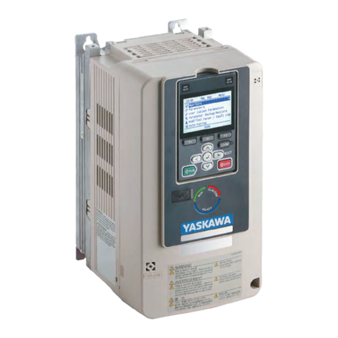
YASKAWA J1000 CIMR-JC series User manual
Other YASKAWA Controllers manuals
YASKAWA
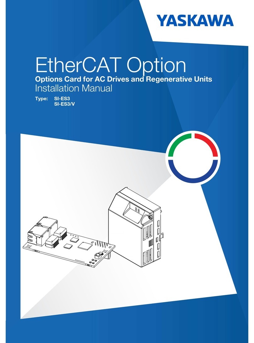
YASKAWA SI-ES3 User manual
YASKAWA
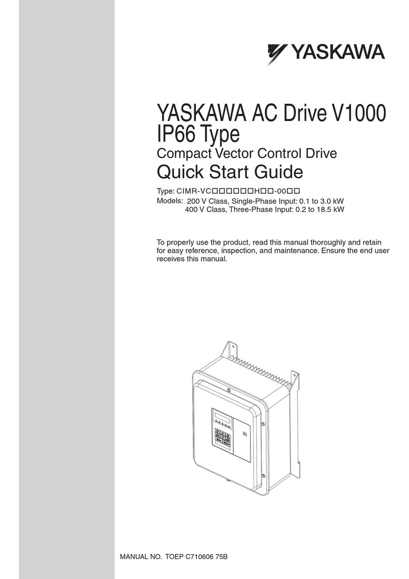
YASKAWA CIMR-VC*****H**-00 series User manual
YASKAWA
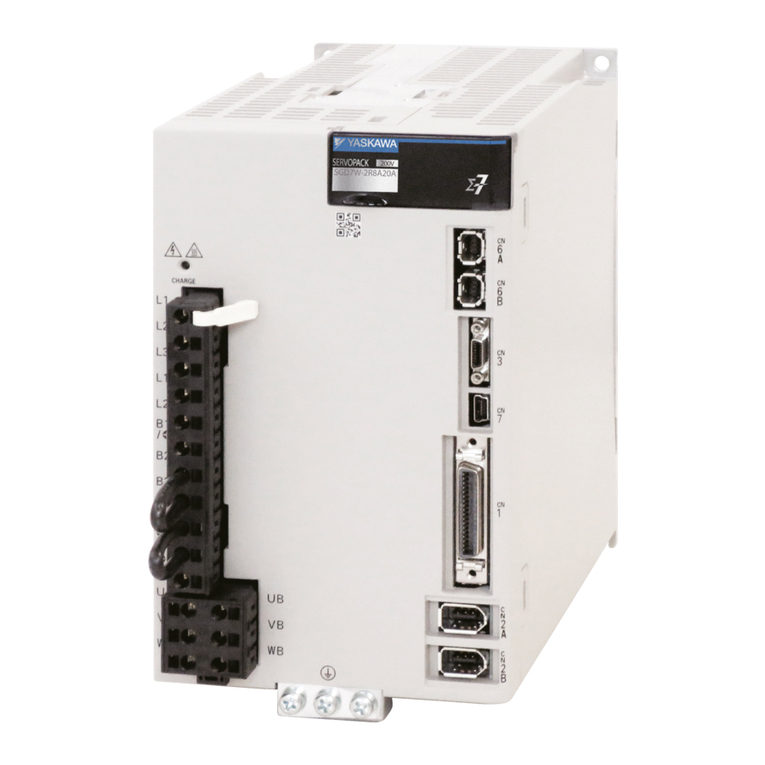
YASKAWA SIGMA-7 Series User manual
YASKAWA
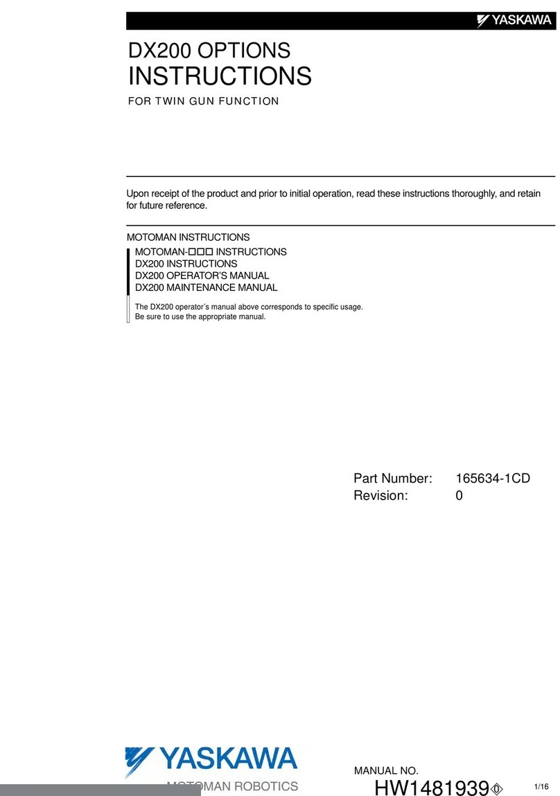
YASKAWA Motoman DX200 User manual
YASKAWA
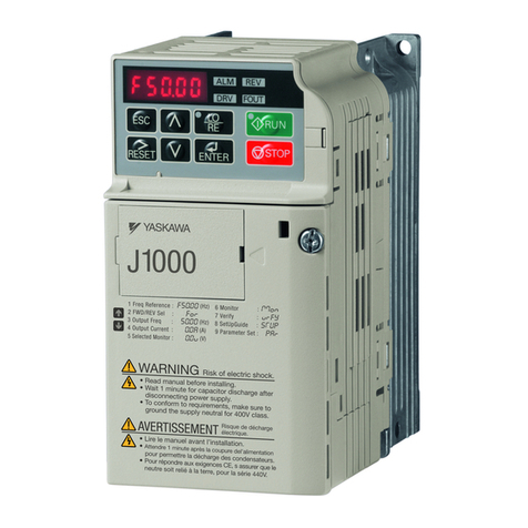
YASKAWA CIMR-JC4A0002BAA User manual
YASKAWA
YASKAWA MP Series Release note
YASKAWA
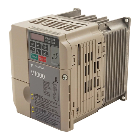
YASKAWA V1000 Series User manual

YASKAWA
YASKAWA L1000A Series User manual
YASKAWA
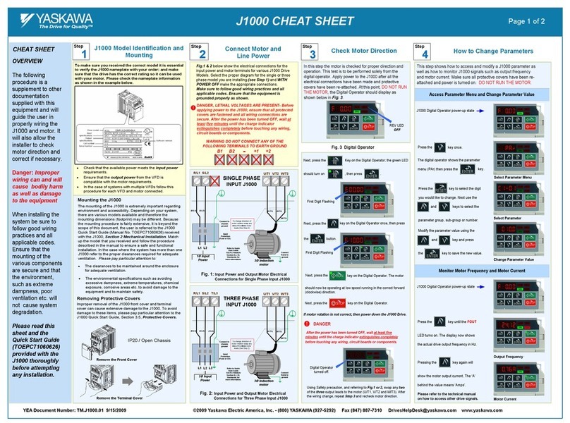
YASKAWA J1000 CIMR-JC series User manual
YASKAWA
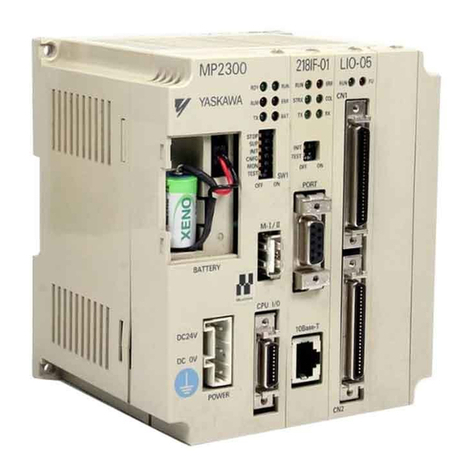
YASKAWA MP2300 User manual
YASKAWA
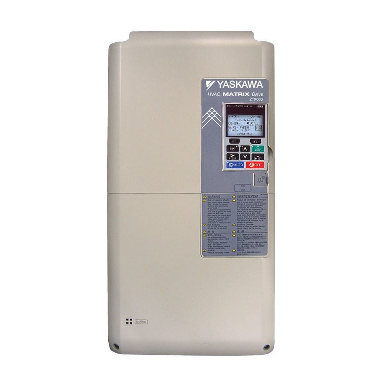
YASKAWA Z1000U Series Owner's manual
YASKAWA
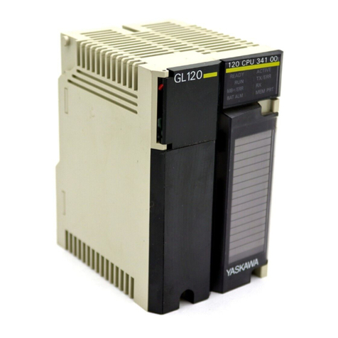
YASKAWA MEMOCON GL120 User manual
YASKAWA
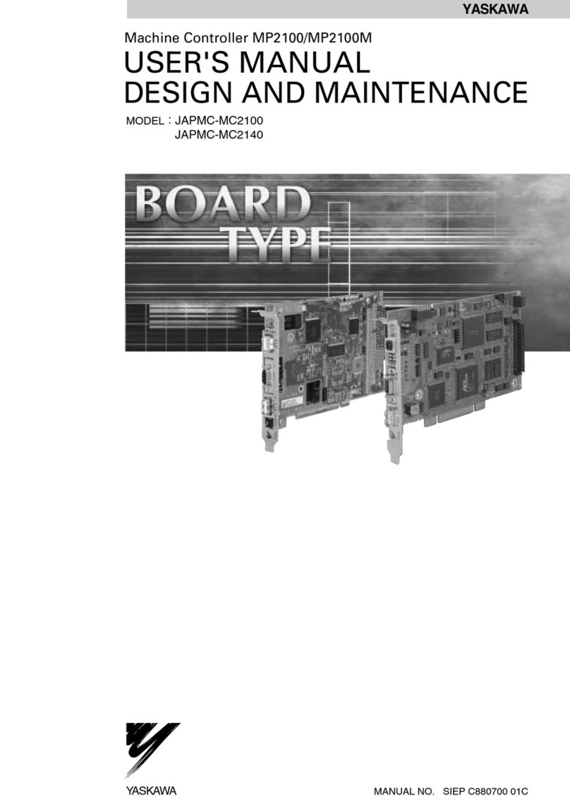
YASKAWA MP2100 Series User manual
YASKAWA
YASKAWA motoman NX100 User manual

YASKAWA
YASKAWA motoman NX100 User manual

YASKAWA
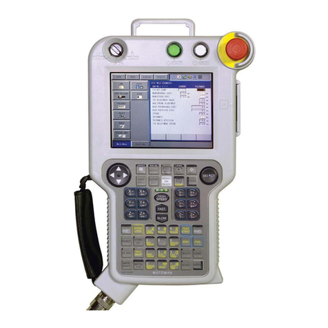
YASKAWA Motoman DX200 User manual
YASKAWA
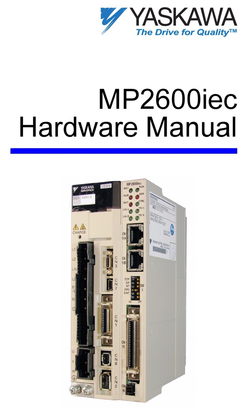
YASKAWA MP2600iec User manual
YASKAWA
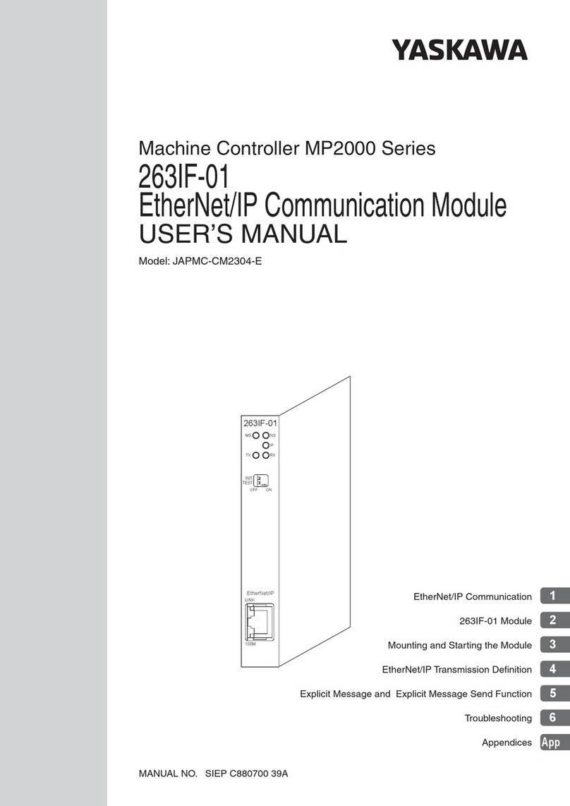
YASKAWA MP2000 Series User manual
YASKAWA
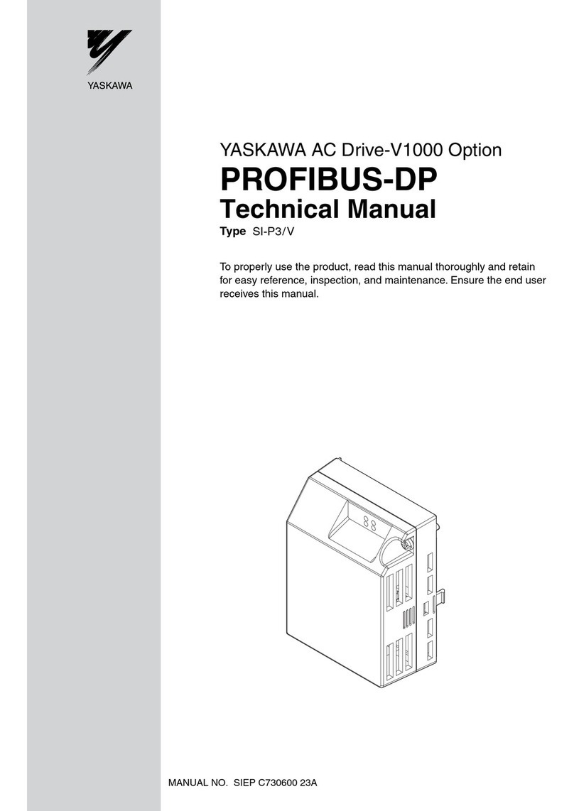
YASKAWA PROFIBUS-DP User manual
YASKAWA
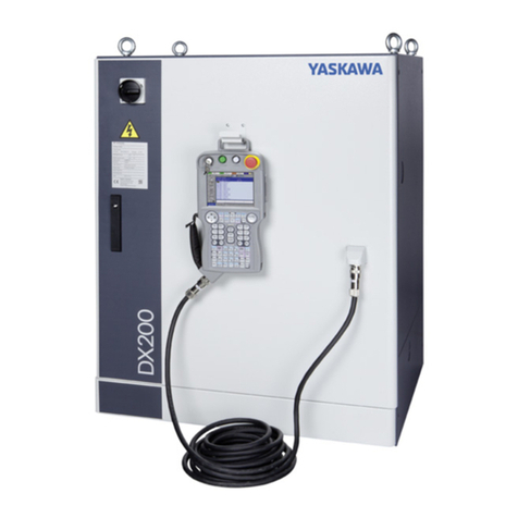
YASKAWA Motoman DX200 User manual
Popular Controllers manuals by other brands

Digiplex
Digiplex DGP-848 Programming guide

Sinope
Sinope Calypso RM3500ZB installation guide

Isimet
Isimet DLA Series Style 2 Installation, Operations, Start-up and Maintenance Instructions

LSIS
LSIS sv-ip5a user manual

Airflow
Airflow Uno hab Installation and operating instructions

ABB
ABB ACS580-01 drives Hardware manual
