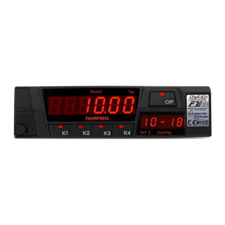
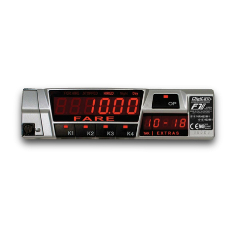
Digitax F2 PLUS User manual

Technical Manual
Installation and Programming
V 1.0
11/06/2020

The information contained here are property of DIGITAX Automotive Electronics Italy, and extremely confidential. Any disclosure, copying, distribution to third
party is strictly prohibited.
2

The information contained here are property of DIGITAX Automotive Electronics Italy, and extremely confidential. Any disclosure, copying, distribution to third party
is strictly prohibited.
3
Index
Introduction..................................................................................................................................................... 4
About this Manual.............................................................................................................................................. 4
Electrical Connections Table............................................................................................................................. 5
Specifications................................................................................................................................................... 6
Connectors - Pins Out....................................................................................................................................... 7
How to Fix the Taximeter ................................................................................................................................. 8
Fixing Plate ......................................................................................................................................................... 8
UNIVERSAL MECCANICAL TRANDUCER: ...........................................................................................................9
How to Assemble................................................................................................................................................ 9
Test Connector............................................................................................................................................... 10
"E-Seal"- Electronic Sealing: 1st Section ....................................................................................................... 11
"E-Seal"- Electronic Sealing: 2nd Section ...................................................................................................... 12
How to Seal the Taximeter............................................................................................................................. 13
Regular Way of Sealing the Taximeter ............................................................................................................. 13
Taximeter Display .......................................................................................................................................... 14
Display Composition and Inscription................................................................................................................ 14
Time Syncro ................................................................................................................................................... 15
For Hire-Stopped-Hired .................................................................................................................................. 16
The Operative Mode......................................................................................................................................... 16
“K” Constant .................................................................................................................................................. 16
(Car Odometer Transmission Ratio) ................................................................................................................. 17
Time and Date Setting.................................................................................................................................... 18
How To Set The Taximeter’s Time And Date .................................................................................................... 18
Diagnostic Self-Test (Check Sum).................................................................................................................... 19
Statistical Memory......................................................................................................................................... 20
How to Read the Statistical Memory Content.................................................................................................. 20
Statistical Memory......................................................................................................................................... 21
How to Print the Statistical Memory Content .................................................................................................. 21
Statistical Memory......................................................................................................................................... 22
How to Erase the Statistical Memory Content ................................................................................................. 22
The Tariff........................................................................................................................................................ 23
General Description.......................................................................................................................................... 23
The Tariff........................................................................................................................................................ 24
How to Program the Tariff................................................................................................................................ 24
Tariff Show..................................................................................................................................................... 25
Tariff Show..................................................................................................................................................... 26
The" ProgDate" .............................................................................................................................................. 27
The "Sel-Function" ......................................................................................................................................... 28
Programming Keys ......................................................................................................................................... 29
Programming Parameters (Questions could be locked depending on some Country specific settings)........... 30

The information contained here are property of DIGITAX Automotive Electronics Italy, and extremely confidential. Any disclosure, copying, distribution to third
party is strictly prohibited.
4
Introduction
About this Manual
The F2 Plus taximeter is designed to be easy to use while remaining very powerful .
This manual is conceived to be user friendly, more graphical and easy to understand.
In the first section are described the electrical connections, the ways to fix and lead the taximeter, how to assemble the sensor
box. The second section explain the meter’s operative modes, the functions and the programming phase.
The third sections contains the description of all the tariff programming parameters.

The information contained here are property of DIGITAX Automotive Electronics Italy, and extremely confidential. Any disclosure, copying, distribution to third party
is strictly prohibited.
5
Electrical Connections Table
PRINTER
TRANSDUCER
GREY (F)
VIOLET (G)
GREEN (H)
YELLOW (J)
Max. 3 watts
Max. 25 watts
WHITE
Fuse 2 A
PASSENGER TOOL
Warning!
The taximeter is not provided with his own set of
fuses. You must install them by yourself following
the scheme. You will be responsible for every
damage that you can cause for the omission of
these fuses.
Digitax rejects every legal responsibility.
Fuse 2 A
RED
RED
Fuse 2 A
Car Lights Switch
+ 12 V
BROWN
BLACK
Fuse 2 A
PINK

The information contained here are property of DIGITAX Automotive Electronics Italy, and extremely confidential. Any disclosure, copying, distribution to third
party is strictly prohibited.
6
Specifications
Power Supply (Vcc): Operating Range: 9 to 16 V
Range of device constant: k = 500 pulses/km to 99999 pulses/km
Resolution of device constant: 1 pulse/km
Range of time tariff: 0.1 s/unit to 6553.5 s/unit or 0.01 s/unit to 655.35 s/unit
Resolution of time tariff: 0.1 s/unit or 0.01 s/unit
Range of distance tariff: 0.1 m/unit to 6553.5 m/unit or 0.01 m/unit to 655.35 m/unit
Resolution of distance tariff: 0.1 m/unit or 0.01 m/unit
Odometer Transducer Input:
input range: 0 to 16 V
level for LOW voltage: 0 V - 0.3 V
level for HIGH input: 6 V to Vcc
maximum frequency: 7 KHz (with k=99999)
high voltage trigger: high - low transition
Passenger Sensor:
Input range: 0 to 12 V
maximum level for LOW input: 1.4 V
Taxi Light Output:
Maximum Current: 2 A
Output Voltage: Vcc
Lights Outputs:
Maximum Current: 1 A
Output Voltage: Vcc
Printer Power Out:
Maximum Current: direct from Vcc input
Output Voltage: Vcc
RS-232 serial ports: Standard COM1, COM2

The information contained here are property of DIGITAX Automotive Electronics Italy, and extremely confidential. Any disclosure, copying, distribution to third party
is strictly prohibited.
7
Connectors - Pins Out
LEGENDA
POWER SUPPLY - connections:
A INPUT BATTERY + 12 VOLTS
B INPUT PASSENGER DETECT SENSOR
C INPUT +12 VOLTS CAR LIGHTS
D INPUT GROUND ( CAR BODY )
E 12 VOLTS (ROOF TOP LIGHT) Max 3 A
F 12 VOLTS POWER OUTPUT (LIGHT 1 ) Max 1 A *
G 12 VOLTS POWER OUTPUT (LIGHT 2 ) Max 1 A *
H 12 VOLTS POWER OUTPUT (LIGHT 3 ) Max 1 A *
J 12 VOLTS POWER OUTPUT (LIGHT 4 ) Max 1 A *
K INPUT BATTERY +12 VOLTS
PERIPHERICALS - connections:
L GROUND
M TXD 2 RS 232 COM 2 TX
N RXD 2 RS 232 COM 2 RX
O AUX 2 INPUT/OUTPUT
P AUX 1 INPUT/OUTPUT
Q PIO 1 INPUT/OUTPUT
R + 12 VOLTS
S PIO 0INPUT/OUTPUT
T RXD 1 RS 232 COM 1 RX
U TXD 1 RS 232 COM 1 TX
TRANSDUCER - connections:
V INPUT 2
W GROUND
X + 12 VOLTS
Y INPUT 1 ( SENSOR )
*Optional Hardware
LEFT VIEW
TRANSDUCER
CONNECTOR
POWER SUPPLY
CONNECTORS
PERIPHERICAL
CONNETTORS

The information contained here are property of DIGITAX Automotive Electronics Italy, and extremely confidential. Any disclosure, copying, distribution to third
party is strictly prohibited.
8
How to Fix the Taximeter
Fixing Plate
Screw 3MA
7x29,5 mmm
Front View
Fixed the bracket
Locking direction
Dashboard
Screw 4MA
7x26 mmm
Sealed to the
taximeter
BY A DOUBLE SIDE
GLUED TAPE
BY A VELCRO STRAP

The information contained here are property of DIGITAX Automotive Electronics Italy, and extremely confidential. Any disclosure, copying, distribution to third party
is strictly prohibited.
9
UNIVERSAL MECCANICAL TRANDUCER:
How to Assemble
TRANSDUCER
Screws B
Screws A
Screws B
Clamps
Shielding
Speedometer
Cable
1) Take out the internal wire
from the shielding.
2) Shorten the shielding by 36
mm
3) Insert both ends of the
shielding in the clamps and
tight the 4 screws B
4) Loosen the 4 screws (A)
and insert the internal wire.
Do not tight the 4 screws A*.
* Attention: when you insert the
internal wire, the dummy shaft must
come out and be disposed off.
Shaft
A) Re-assemble the transmission cable in the car, connecting
it to both the gear box and the odometer.
B) Drive about 100 m to allow the internal wire to find its
original position.
C) Tight the 4 screws A.
D) Insert the sensor’s probe.
E) Fix the sensor’s cap to end the sensor’s assembling
operation and to have the sensor fully operative.
Electrical Connections
Red Cable = Power Supply
(5 Vcc to 24)
White Cable = Output Signal
(open collector)
Shield = Ground
Screws (A)
Screw B
Screw B
Clamps
36 mm
Sensor Capsule

The information contained here are property of DIGITAX Automotive Electronics Italy, and extremely confidential. Any disclosure, copying, distribution to third
party is strictly prohibited.
10
upside view
Side view
Front view
PINK
VIOLET
TIME BLOCK INPUT
FARE INCREMENT PULSE OUTPUT
YELLOW DISTANCE PULSES OUTPUT
RED DISTANCE PULSE INPUT
GREY GROUND
BROWN TIME PULSES INPUT
GREEN TIME PULSES OUTPUT
Test Connector

The information contained here are property of DIGITAX Automotive Electronics Italy, and extremely confidential. Any disclosure, copying, distribution to third party
is strictly prohibited.
11
"E-Seal"- Electronic Sealing: 1st Section
The “E-Seal” is a non-erasable memory in two sections where, in the first section, are recorded the last 100
alterations made on the programming functions. These are shown on the displays or printed, with detailed
information of: index nr, event, date, year and hour. The second section is made of permanent, non-resettable,
progressive individual events counter, incremented by each event alterations without details. The first section is
by default a FIFO buffer, with the last 100 events recorded, but can be configured if approved by some country
specific settings to disable the FIFO and block the taximeter when it reaches its maximum capacity. The second
sections (counters) is never FIFO, and when reaches its maximum capacity of 1000 events on any counter, the
taximeter shows “ESEAL FULL” and it is blocked until the mechanical seal is broken and the taximeter is again
initialized.
MAIN DISPLAY
PRINTED REPORT
DESCRIPTION
EVENTS
K-CONST
Constant “K” calibration
Autotest
A.DEFAULT
ESeal Auto-Default due to structure corruption
Auto-default
TARIFF
Tariff Programming
Tariff
CLOCK
Clock setting
Clock
SYNCRO
Clock +/- 2’ syncro
Syncro Clock
TICKET
Ticket programming
Ticket change
STAT.MEM.
Statistical Memory block 2 reset
Clear memo
G.DEFAULT
Manual Taximeter General Default
General Default
BIOS
Firmware changed
Bios Change
The "E-Seal" Reading is included in a multi menu. This is the procedure to enter it:
1) Select FOR HIRE position
2) Keep pressed K2 to enter in the menu selection
3) Select E-Seal menu by pressing K2 key multiple times
4) Confirm by K4 the E-Seal reading.
Now the first Record is showed on the display (see figure 1)
To increase the record index press K4
To decrease the record index press K3
To print the on reading menu press K1 (switch on the printer)
1st SECTION
This section shows the events list. For each record, the secondary display consecutively shows date, year and
time and, depending on record type, an additional info: the K Constant for Autotest events, the tariff CRC for
Tariff changes, the bios CRC for Bios changes, the ticket CRC for Ticket changes.

The information contained here are property of DIGITAX Automotive Electronics Italy, and extremely confidential. Any disclosure, copying, distribution to third
party is strictly prohibited.
12
"E-Seal"- Electronic Sealing: 2nd Section
It is possible to toggle between 1st section and 2nd section pressing K2 key in any moment.
2nd SECTION

The information contained here are property of DIGITAX Automotive Electronics Italy, and extremely confidential. Any disclosure, copying, distribution to third party
is strictly prohibited.
13
How to Seal the Taximeter
Regular Way of Sealing the Taximeter
Sealing Screw
Sealing Bush
Sealing Wire
Sealing Lead Disk
Sealed to the
bracket
Sealed to the
taximeter
Sealing Plastic Disk
Sealing Screw
Sealing Bush
Programming Cover
Special Way of Sealing
Sealed to the
bracket
Sealed to the
taximeter

The information contained here are property of DIGITAX Automotive Electronics Italy, and extremely confidential. Any disclosure, copying, distribution to third
party is strictly prohibited.
14
M
Taximeter Display
Display Composition and Inscription
1. Day / Night Indication
2. Tariff Index
3. Fare Display
4. Status (For Hire, Hired, Stopped)
5. Secondary Display
6. Passenger detection status (when it’s blinking)
7. Description (extras/time)
8. Metrological Inscriptions Plate
9. Serial Number
10. Factory Label
1
2
3
4
7
5
8*
E-Mark Number
Approval E-Mark Number
Verification Year
Notified Body Number
EC Type examination certificate number
Bios Country Version
K-Constant Range
Temperature Range
Voltage Range
9
8*
6
10
ITALTAX Srl
Via dell’Industria 16
62017 Porto Recanati (MC)

The information contained here are property of DIGITAX Automotive Electronics Italy, and extremely confidential. Any disclosure, copying, distribution to third party
is strictly prohibited.
15
Time Syncro
The F2 Plus time clock can be synchronized to exactly minute 00 of each hour, if at least 7 days are passed from
last synchronization or clock change.
The Time Synchro works only if the manual time setting is disabled (Q269 = Yes).
For example, when the taximeter clock is between 11:58 and 12:02, the clock can be synchronized at exactly
12:00 am by pressing the K2 + K4 keys at the same time.
A similar operation can be done at any hour of the day, and it will be accepted only if previous clock change
was done at least 7 days before.
The procedure ends automatically.

The information contained here are property of DIGITAX Automotive Electronics Italy, and extremely confidential. Any disclosure, copying, distribution to third
party is strictly prohibited.
16
For Hire-Stopped-Hired
The Operative Mode
The taximeter works with 3 main statuses:
In any status, it is possible to have different functions active by pressing one of the 5 taximeter’s
buttons:
OP - K1 - K2 - K3 - K4
FOR HIRE
STOPPED
HIRED
In FOR HIRE position, the following sequence
can be obtained by pressing the OP button:
FOR HIRE
FOR HIRE
STOPPED
HIRED
FOR HIRE - STOPPED - HIRED and corresponding button’s functions
It’s the position selected by the Taxi Driver when the vehicle is
parked or it moves without any passenger on board.
• The left display is turned off, or shows FOR HIRE
• The right one shows the clock.
Once the taxi starts the trip, the Taxi Driver selects the
Hired position by pressing OP button.
The “Taxi” roof sign turns off and the taximeter starts the
fare calculation by distance or time.
• The left display shows the tariff value
• The right one shows: in the left digit the tariff number,
in the right ones the clock.
At the end of the trip, the Taxi Driver has to select the
Stopped position to calculate the final fare.
He does it by pressing the OP button. The waiting time is
thus blocked.
• The left display shows the final fare
• The right one shows the total extras
FOR HIRE
HIRED
STOPPED
Chrono start Chrono Pause
Shows the clock in the right display
Shows the date in the left display (Day - Month)
Shows the year in the left display
Change the tariff (if enabled).
The current tariff is shown in the left digit of the right display
Insert the Extra n° 1 (if enabled)
Insert the Extra n° 2 (if enabled)
Reset the added Extras
Insert the Extra n° 3 (if enabled).
Insert the Extra n° 4 (if enabled)
Adds the Extras to the fare
Splits the final fare
• The left display shows the normal fare
• The right one shows the total extras.

The information contained here are property of DIGITAX Automotive Electronics Italy, and extremely confidential. Any disclosure, copying, distribution to third party
is strictly prohibited.
17
“K” Constant
(Car Odometer Transmission Ratio)
The “K Constant” is the number of pulses per Kilometer emitted by a transducer and received by a taximeter.
K Constant = Pulses/km
The pulses can be emitted by the car’s electronic transducer or, if the car is not provided of it, by the Digitax
mechanical one. This constant can be already known or be tested on road.
How to insert a known K-Constant value
Take out the taximeter programming cover
Select For Hire position.
Insert the Black Programming Key in its slot.
Press K2 and K3 buttons at the same time.
The “For Hire - Stopped - Hired” signs light on together
The fare display shows the programmed K-Constant value.
The extras display shows the meters to be travelled for the Autotest
Press K2 button to increase the pulses/km number.
Press K1 button to decrease the pulses/km number.
Press OP button to end the procedure and go back to For Hire position
Take out the Black Programming Key from the taximeter.
Take out the taximeter programming cover
Select For Hire position.
Insert the Black Programming Key in its slot.
Press K2 and K3 buttons at the same time.
The left display shows “Attest” for a few seconds.
Now the “For Hire - Stopped - Hired” signs with light.
Press K3 button to reset all meter’s counters.
The extras display will show the value 0.
Start drive the vehicle at 30 km / h maximum.
Drive to the Autotest End Point (1 km).
Once the Autotest End Point is reached, press K4 button to finish the
Autotest. Now the taximeter will calculate and store the new K-
Constant. The fare display will show the new K-Constant value.
The extra display will show the number of pulses generated during the
Autotest.
Press the OP button in order to finish the Autotest procedure and come
back to For Hire position.
Take out the Black Programming Key from the taximeter.
How to find out the K-Constant value (Autotest)
Follow this procedure to find out the car transmission ratio (K-constant).
For a right procedure, it must be done in a road with a carefully marked distance of 1 km (default).
Align carefully the car’s front wheels with the test distance‘s start line.
Autotest Start Point
Autotest End Point
1 Kilometer at Max 30 Km/Hour.
K Constant value Pulses/Kilometer
Meters
Number of Pulses
received during the Autotest
New recorded K-Constant
K Constant value Pulses/Kilometer
Meters

The information contained here are property of DIGITAX Automotive Electronics Italy, and extremely confidential. Any disclosure, copying, distribution to third
party is strictly prohibited.
18
Time and Date Setting
How To Set The Taximeter’s Time And Date
Select For Hire position.
Press K1 and K3 at the same time. The left display will show
“Time” for a few seconds.
Now the signs “FOR HIRE” and “STOPPED” starts blinking.
The big display shows in the left digits the day number and in
right digits the month..
The small display shows the time in HH-MM format
To set the Day number press K1 button.
To set the Month number press K2 button.
To set the Hour press K3 button.
To set the Minutes press K4 button.
Press OP button to enter in the Year programming.
To decrease the Year number press K1 button.
To increase the Year number press K2 button.
Press K3 button to set the taximeter base year.
Press OP button to end the programming procedure and go
back to For Hire position

The information contained here are property of DIGITAX Automotive Electronics Italy, and extremely confidential. Any disclosure, copying, distribution to third party
is strictly prohibited.
19
Diagnostic Self-Test (Check Sum)
With this procedure it is possible to:
calculate the tariffs check sum
print out the tariff program.
verify segment display correct functionality
How to enter the Self- Test function
The Check Sum
To test Data Integrity, the Tariff Data is signed with a CRC16 function.
A 16 bit CRC Check Sum is therefore calculated from the Tariff Data, and saved for a future reference. The only two sections
that are out from the check sum are the unique vehicle and owner parameters, like: "k" constant and ticket heading.
a) Tariff Programming through PC or Smart key: if the data buffer is corrupted, due to errors in data transmission,
system errors or tampering, the CRC16 Check Sum will be different from that stored for comparison.
b) At each Trip the Taximeter recalculate the Checksum of the Tariff and compares with the stored CS. reference;
and in case of data corruption it auto locks the meter showing at any tentative of start a trip the message "Error
Csum" so it can' t work with a wrong tariff until reprogrammed.
c) It is possible to recalculate the check sum manually, IE, by Inspectors in every moment but only when the meter
is in FOR HIRE mode, by pressing together K1 + K4, to verify that the meter is programmed with the right tariff.
The CRC16 Check Sum is a number between 0 and 65535, and can be displayed on the Taximeter when wished.
ALGORITHM SHORT DESCRIPTION:
The CRC 16 Check Sum calculation in the Taximeter is the (CCITT CRC16).
The polynomial used is:
Hex : 0x1021
Bin : 1000000100001
Dec : 4129
Register Init is Hex : 0000
CHECK = Hex : 31C3
Select For Hire position.
Press K1 and strike K4.
Both displays will show in sequence the numbers from 0 to 9 in
all display digits. Check if all numbers are correct.
After that, an 8 digit will be shown moving from right to left,
verify that only one digit at a time is on, otherwise there might
be some short circuit between LEDs.
The printer, if connected to the taximeter and powered on, will
print out all the taximeter setup.
To increase the start block number press K2 button before print
start, in this way tariff block 0 will not be printed (to reduce
report length).
To print also ProgDates records, press K1 button before print
start. ProgDates report will be printed after tariff one.
After a few seconds the main display will show the tariff
checksum (CRC16 of all tariff parameters) so that each tariff will
have its own resulting checksum value. The secondary display
will show the firmware country version.
At the end of procedure the taximeter will go back in For Hire

The information contained here are property of DIGITAX Automotive Electronics Italy, and extremely confidential. Any disclosure, copying, distribution to third
party is strictly prohibited.
20
Statistical Memory
How to Read the Statistical Memory Content
The F2 Plus taximeter records and keeps statistical data in 2 Memory Blocks, each one divided in 20 locations.
The Block 1 allows to read, print or erase its information whenever desired.
The Block 2 allows to read and print its content but not to erase it.
The Block 1 is useful to control and analyze the working shift data.
The Block 2 for its nature is cumulative and not erasable.
How to read the memory blocks information
Locations Content
Select For Hire position.
Press K1 and K2 at the same time.
The big display will show “Statis” for a few seconds.
Now the sign “FOR HIRE” starts blinking.
The extras display will show: in the left digit the block number
and in the right digit the statistical memory number (1-20).
The fare display will show in the right digits the selected
statistical memory data value.
To increase the memory number press K2 button.
To decrease the memory number press K1 button.
Press K3 button to toggle between Block 1 and Block 2.
Press OP button to end the reading procedure and go back to
For Hire position.
Loc. Block n. 1 data type
1) Trips Quantity integer
2) Units Quantity integer
3) Total Amount (all including) currency
4) Fare Amount currency
5) Extras Amount currency
6) Discounts Amount currency
7) VAT Amount currency
8) Amount per km (or mile) currency
9) Total Distance km/mi (1 decimal)
10) Distance in Hired + Stopped km/mi (1 decimal)
11) Distance in Over-Speed km/mi (1 decimal)
12) Distance Black (no passenger) km/mi (1 decimal)
13) Time in Hired + Stopped hours (1 decimal)
14) Time moving in For Hire hours (1 decimal)
15) Time Paid in Hired hours (1 decimal)
16) Custom amount 1 (available) currency
17) Custom amount 2 (available) currency
18) Custom amount 3 (available) currency
19) Custom defined 1 (available) to be defined
20) Custom defined 2 (available) to be defined
1) Trips Quantity integer
2) Units Quantity integer
3) Total Amount (all including) currency (no decimals)
4) Fare Amount currency (no decimals)
5) Extras Amount currency (no decimals)
6) Discounts Amount currency (no decimals)
7) VAT Amount currency (no decimals)
8) Amount per km (or mile) currency (no decimals)
9) Total Distance km/mi (no decimals)
10) Distance in Hired + Stopped km/mi (no decimals)
11) Distance in Over-Speed km/mi (no decimals)
12) Distance Black (no passenger) km/mi (no decimals)
13) Time in Hired + Stopped hours (no decimals)
14) Time moving in For Hire hours (no decimals)
15) Time Paid in Hired hours (no decimals)
16) Custom amount 1 (available) currency (no decimals)
17) Custom amount 2 (available) currency (no decimals)
18) Custom amount 3 (available) currency (no decimals)
19) Custom defined 1 (available) to be defined
20) Custom defined 2 (available) to be defined
Loc. Block n. 2 data type
Table of contents
Other Digitax Automobile Accessories manuals
