Digitax X-One android Assembly instructions

Mobile Data Terminal
Technical Manual
Installation and Programming
ver.1.18
hardware v.2
23/05/2021


The information contained here are property of DIGITAX Automotive Electronics Italy, and extremely confidential. Any disclosure, copying, distribution to third
party is strictly prohibited.
3
Introduction ..............................................................................................................................................................................4
Appearance ...............................................................................................................................................................................5
How to Seal the MDT..............................................................................................................................................................8
Measures...................................................................................................................................................................................9
Electrical Connection Table...................................................................................................................................................10
Electrical Specifications ........................................................................................................................................................11
Blocking Wires.........................................................................................................................................................................12
Dashboard Fitting....................................................................................................................................................................14
Windscreen Fitting..................................................................................................................................................................16
Combo Antenna Installation ..................................................................................................................................................17
Connectors and Cables...........................................................................................................................................................18
Ports Mapping..........................................................................................................................................................................20
Mechanical Movement Sensor ........................................................................................................................................21
User and Demo Software .......................................................................................................................................................22
Note............................................................................................................................................................................................29
INDEX

The information contained here are property of DIGITAX Automotive Electronics Italy, and extremely confidential. Any disclosure, copying, distribution to third
party is strictly prohibited.
4
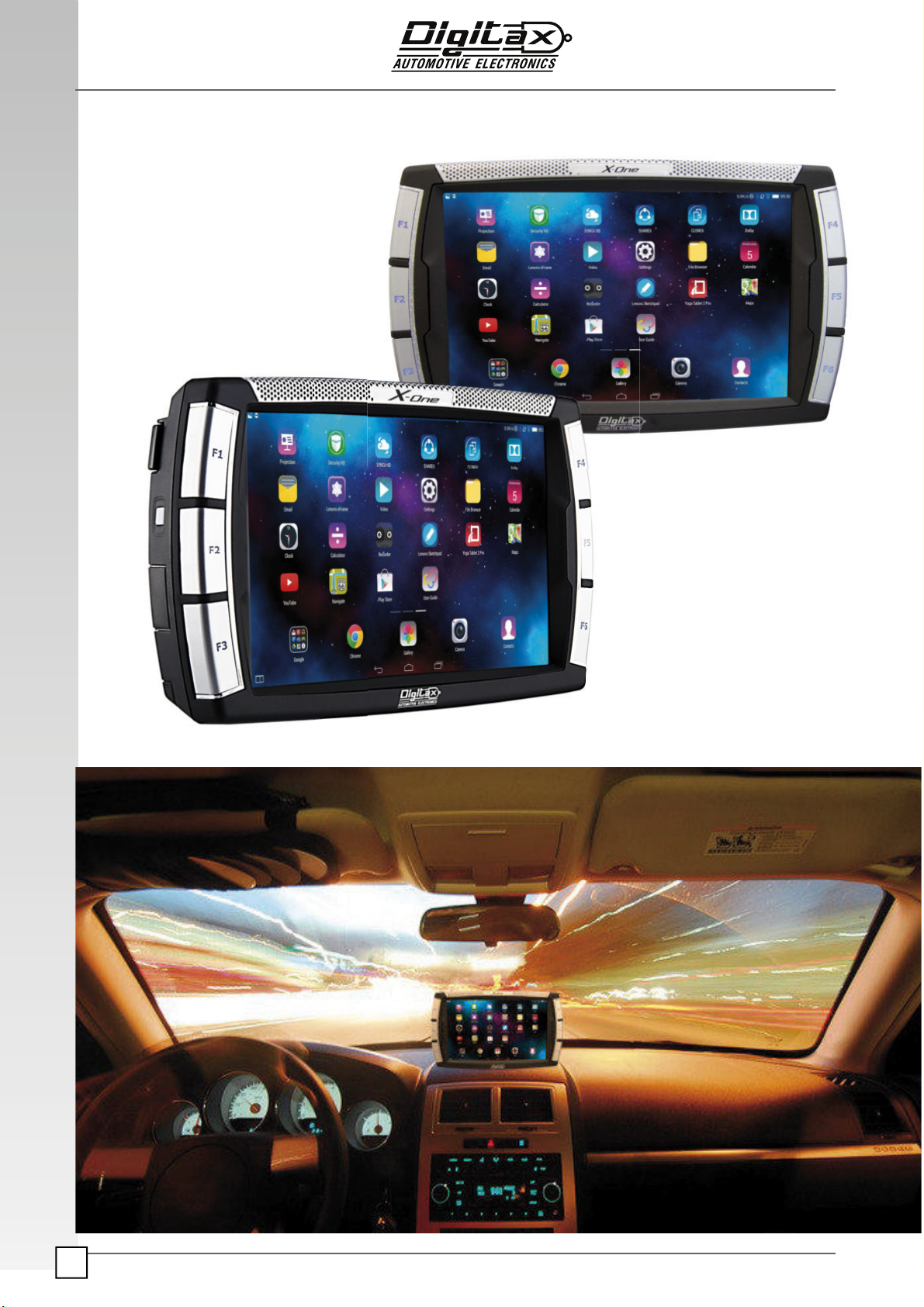
The X-ONE Android is designed to be, at the same !me, easy to use and extremely powerful. This
manual is conceived to be user friendly, more graphical and easy to understand.
In the "rst sec!on are described the electrical connec!ons, the ways to "x and lead the, how to
assemble the sensor box.
The second sec!on explain the meter’s opera!ve modes, the func!ons and the programming
phase (Autotest, Sta!s!cal Memory, “Trip by Trip” bu#er and the Tari# programming).
The third sec!ons contains the descrip!on of all the tari# programming parameters.
Introduction
About this Manual
The information contained here are property of DIGITAX Automotive Electronics Italy, and extremely confidential. Any disclosure, copying, distribution to third
party is strictly prohibited.
5
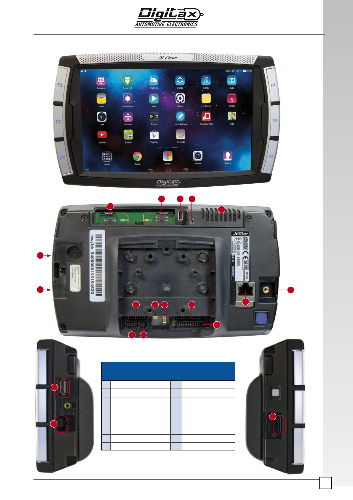
Main Connectors Panel
Appearance
13
15 2 10
12
11
16
Main Connectors Panel
1GPRS Antenna MMCX jack 9Headphone/Mic Jack
2GPS AntennaSMB plug 10 Digital I/O - USB
3
Mini Client USB port for Ac-
tiveSync Connection
11 MDT Connector
Printer Connector
4Mov Sensors Connector/Can 12 Sim Card 1 Holder
5Power Connector 13 Speaker
6Serial COM 14 Micro SD Slot
7Sim Card 2 Holder 15 Test Connector
8Host USB Port 16 Lan Ethernet
6
4
14
93
8
15
8
15
14
7
The information contained here are property of DIGITAX Automotive Electronics Italy, and extremely confidential. Any disclosure, copying, distribution to third
party is strictly prohibited.
6

The information contained here are property of DIGITAX Automotive Electronics Italy, and extremely confidential. Any disclosure, copying, distribution to third
party is strictly prohibited.
7
The information contained here are property of DIGITAX Automotive Electronics Italy, and extremely confidential. Any disclosure, copying, distribution to third
party is strictly prohibited.
8
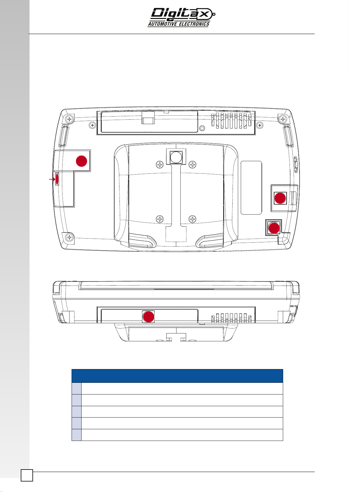
How to Seal the MDT
Regular Way of Sealing the Mobile Data Terminal
X-One MDT’s Seals
1USB Seal
2Tariff Cover Seal
3SD Sealing Cover
4MDT Head Seal
5SIM CARDs Cover Seal
Rear View
Top View
1
2
3
4
5
The information contained here are property of DIGITAX Automotive Electronics Italy, and extremely confidential. Any disclosure, copying, distribution to third
party is strictly prohibited.
9
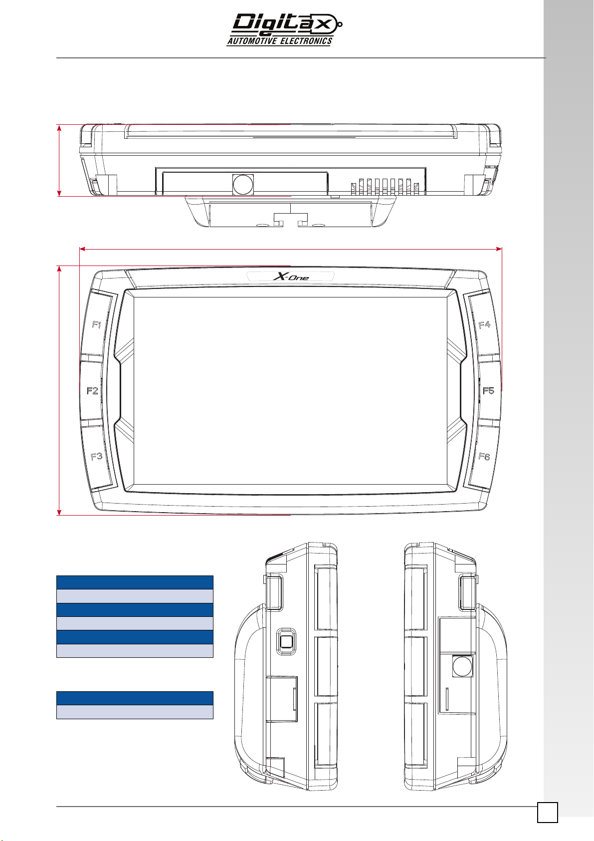
Top
Front
Dimensions (in millimeters)
Width
204
Height
120
Depth
35
Weight (in grams)
X-One
560
Measures
Right Side View Left Side View
204,00
120,00 35,00

The information contained here are property of DIGITAX Automotive Electronics Italy, and extremely confidential. Any disclosure, copying, distribution to third
party is strictly prohibited.
10
Panic Buon
PINK
RED x 2
BLACK
fuse 2 A
ENGINE
WHITE
fuse 2 A
USB CLIENT
USB HOST
COM
TRANSDUCER / CAN
ODOMETER
PRINTER
Input / Output
fuse 2 A
CAR LIGHT SWITCH
+12 V
BROWN
WHITE/VIOLET
GREY (F) Output AITP
Output AITP
Output AITP
Output AITP
Output AITP
Input AITP
GREEN (H)
VIOLET (G)
YELLOW (J)
fuse 2 A
fuse 2 A
fuse 2 A
fuse 2 A
ANTENNA
Electrical Connection Table

The information contained here are property of DIGITAX Automotive Electronics Italy, and extremely confidential. Any disclosure, copying, distribution to third
party is strictly prohibited.
11
Electrical Specifications
Power Supply (Vcc): Operating Range: 8 to 32 V
Range of device constant: k = 500 km•¹ to 65535 km•¹
Resolution of device constant: 1 km•¹
Range of time tariff: 0.10¹ CU/h to 6553.50 CU/h
Resolution of time tariff: 0.10 CU/h
Range of distance tariff: 0.10 CU/km to 6553.50 CU/km
Resolution of distance tariff: 0.10 CU/km
Odometer Transducer Input:
input range: 0 to 32 V
level for LOW voltage: 0 - 0.3 V
level for HIGH input: 5 - Vcc to 32 V
maximum frequency: 1 KHz
high voltage trigger: high - low transition
Passenger Sensor:
Input range: 0 to 32 V
maximum level for LOW input: 1.4 V
Engine Input:
Input range: 0 to 32 V
maximum level for LOW input: 1.4 V
Taxi Light Output:
Maximum Current: 3 A
Output Voltage: Vcc
Lights Outputs:
Maximum Current: 1 A
Output Voltage: Vcc
Printer Power Out:
Maximum Current: direct from Vcc input
Output Voltage: Vcc
RS-232 serial ports: COM1, COM2
Android COM5, COM6, COM7
(optional COM8, COM10, COM11, COM12)
Panic Button
The information contained here are property of DIGITAX Automotive Electronics Italy, and extremely confidential. Any disclosure, copying, distribution to third
party is strictly prohibited.
12
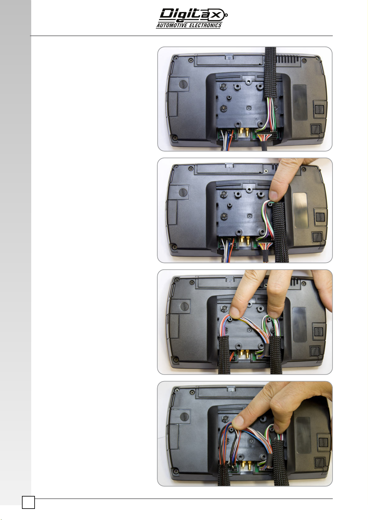
Blocking Wires
Place the connector’s wires as indicated
in the following images.
The information contained here are property of DIGITAX Automotive Electronics Italy, and extremely confidential. Any disclosure, copying, distribution to third
party is strictly prohibited.
13
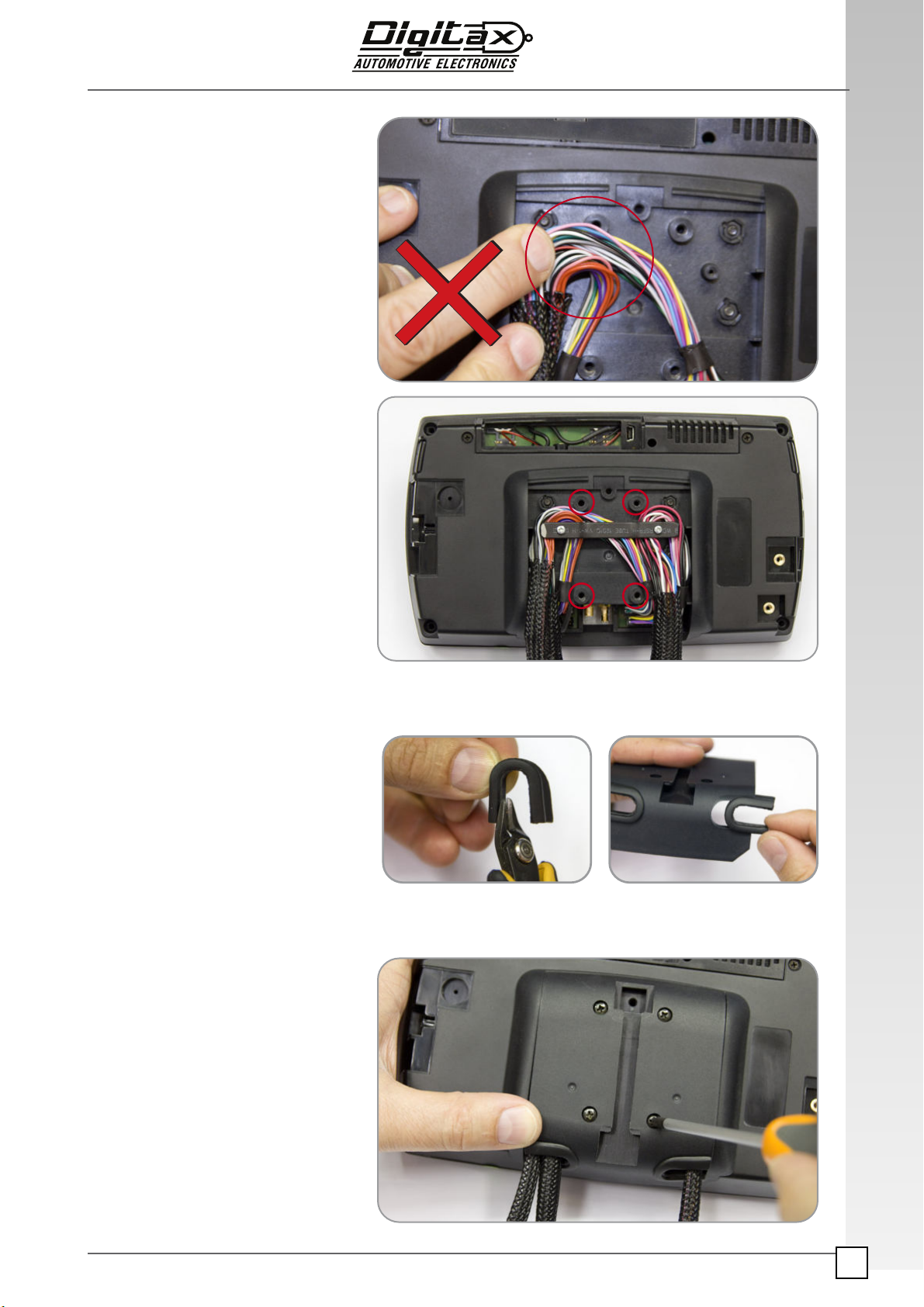
Blocking Wires
Be sure to not cover with the wires the screw
holes
Fix them with the cable blocking plate
Close the back connectors cover fixing the
screws.
Cut the rubber cover and place both in the
back cover.

The information contained here are property of DIGITAX Automotive Electronics Italy, and extremely confidential. Any disclosure, copying, distribution to third
party is strictly prohibited.
14
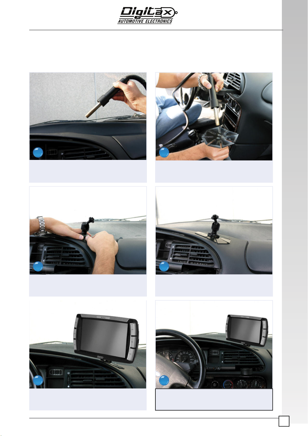
Dashboard Fitting
Clean the dashboard surface that the bracket is to
be fixed to with a clean cloth with alcohol or a suit-
able cleaning (de-grasing) solution
Place the bracket in position without removing the
protective film.
Carefully model the bracket wings to fit the dash-
board.
Make sure the surface is grease and polish free.
Press the bracket wings down into position on the
dashboard.
Remove the protective film from the glue pad on the
base of the bracket.
1 2
3
5
4
6
The information contained here are property of DIGITAX Automotive Electronics Italy, and extremely confidential. Any disclosure, copying, distribution to third
party is strictly prohibited.
15
Dashboard Fitting
Gently warm the dashboard where the bracket is to
be fitted.
Firmly press the bracket into position to obtain the
best adhesion pressure.
Fix the X-One to the bracket using the screws
provided.
Gently warm the adhesive pad on the bracket in the
same way.
Adjust the ball bracket so the face place is in the
best position to allow the X-One to be fitted to it.
Adjust the bracket so the mdt screen is in the best
position for the driver.
7 8
9
11
10
12
The information contained here are property of DIGITAX Automotive Electronics Italy, and extremely confidential. Any disclosure, copying, distribution to third
party is strictly prohibited.
16
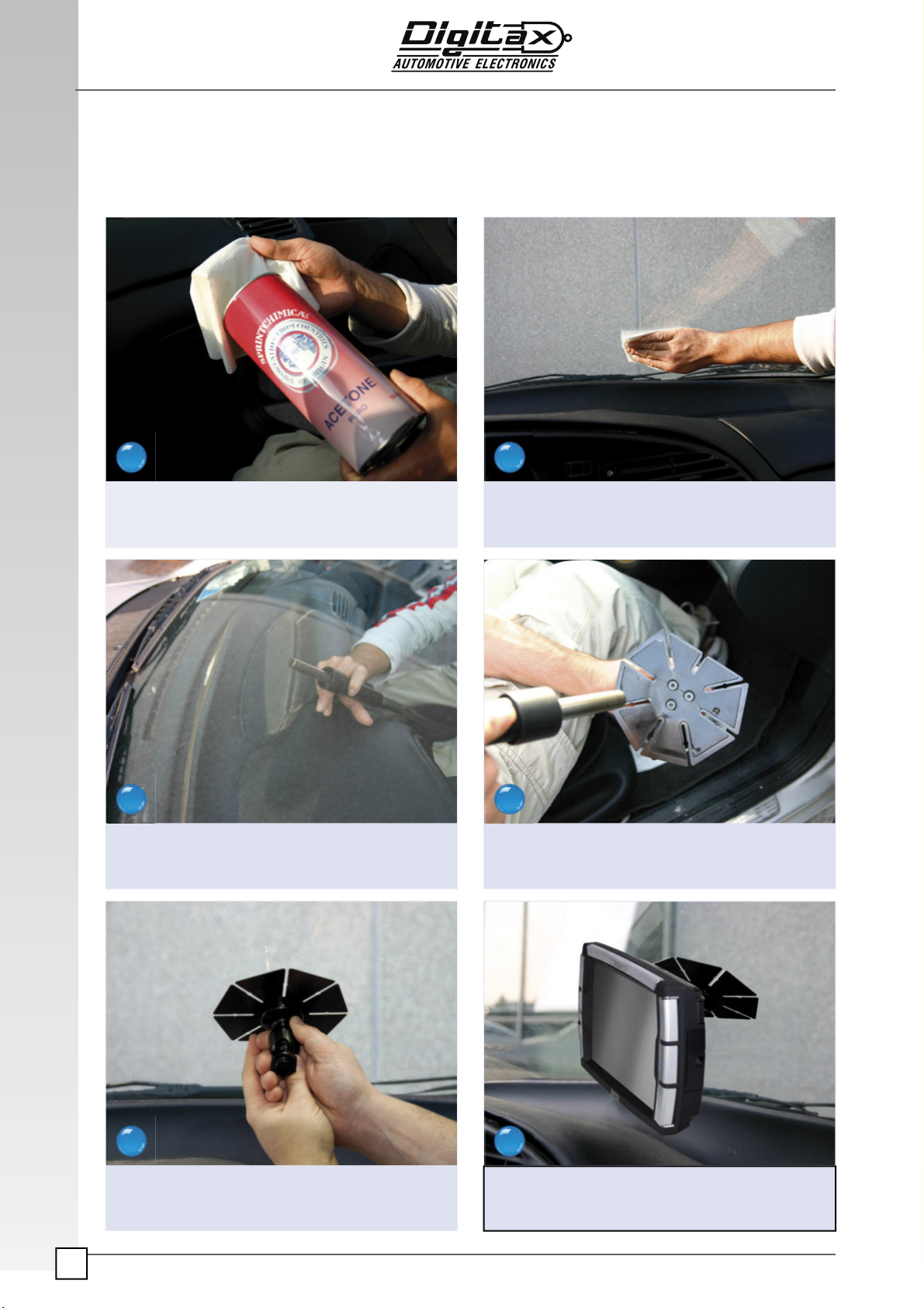
Windscreen Fitting
Make sure the required area is clean, grease and
polish free.
Warm the glass where the bracket is to be fitted.
Firmly press the bracket onto the glass to obtain the
best adhesion possible.
Make sure the required area is clean, grease and
polish free.
Remove the protective film from the adhesive pad
on the base of the bracket.
Using the screws provided fix the MDT to the
bracket.
1 2
3
5
4
6
The information contained here are property of DIGITAX Automotive Electronics Italy, and extremely confidential. Any disclosure, copying, distribution to third
party is strictly prohibited.
17
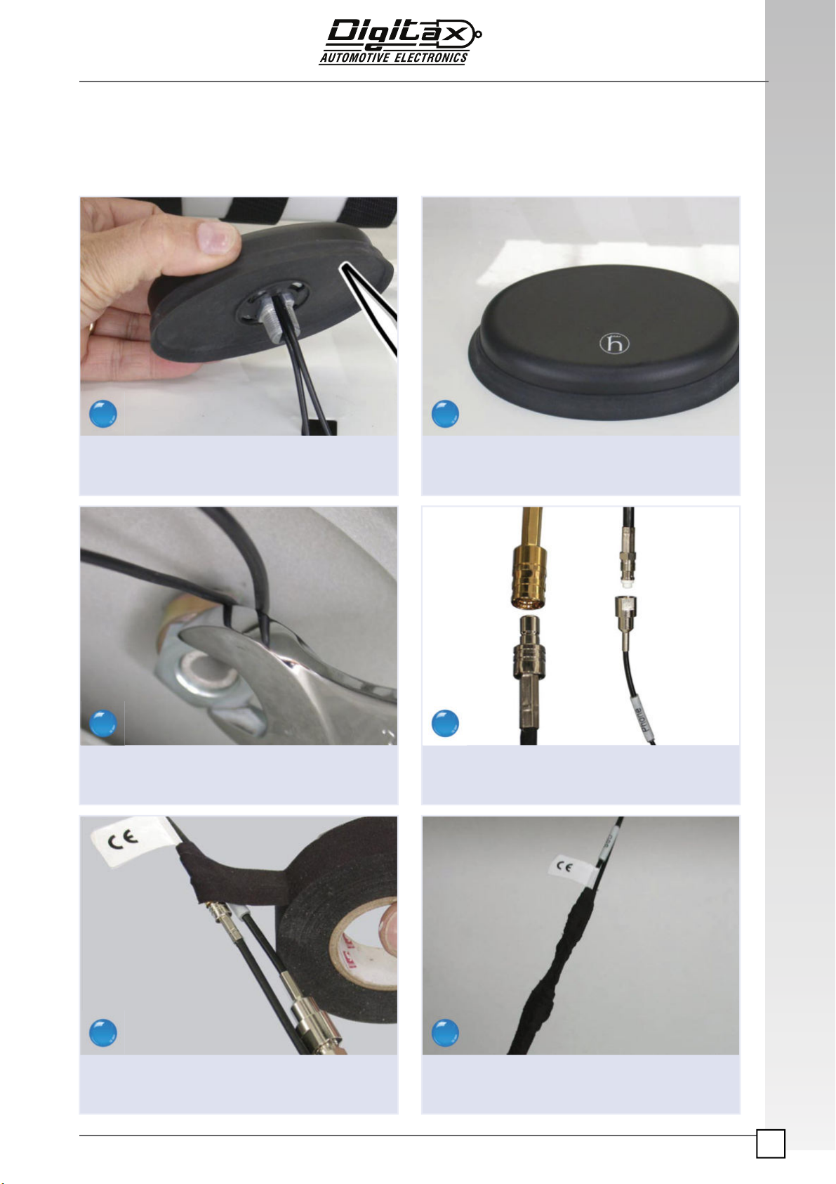
Combo Antenna Installation
Apply sealing silicone to the base of the antenna.
Secure the antenna tightly into position with the
22mm nut.
Tape up the antenna connection.
Place the antenna into position.
Connect the antenna cables to the antenna.
Tape up the antenna cables each 40-50 cm.
1 2
3
5
4
6
The information contained here are property of DIGITAX Automotive Electronics Italy, and extremely confidential. Any disclosure, copying, distribution to third
party is strictly prohibited.
18
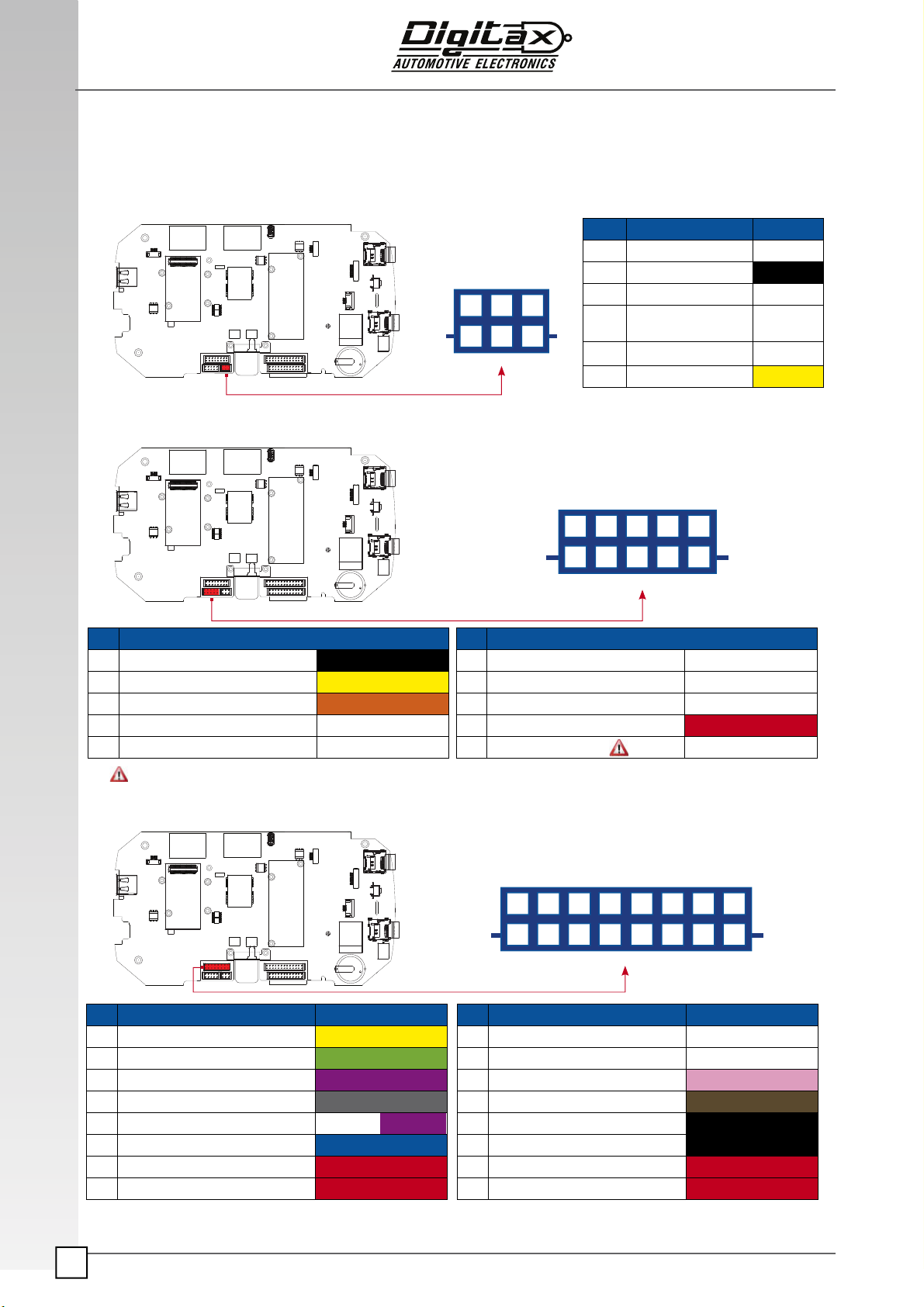
Connectors and Cables
PIN FUNCTION PIN FUNCTION
1 GND BLACK 6 COM1 TXD
2 Printer / COM2 TXD YELLOW 7 COM1 RXD
3 Printer / COM2 RXD ORANGE 8 PIO !, Dallas 1 Wire Net
4 Aux2 Input, ac"ve low 9 +8/32V OUTPUT RED
5 Aux1 Input, ac"ve low 10 PIO 1 Input
PRINTER, I/O
POWER
ODOMETER / CAN
PIN FUNCTION CABLE COLOUR PIN FUNCTION CABLE COLOUR
1 POWER 4 AITP YELLOW 9 POWER 5 WHITE
2 POWER 3 AITP GREEN 10 POWER 5 WHITE
3 POWER 2 AITP VIOLET 11 INPUT Sensor Ac"ve Low PINK
4 POWER 1 AITP GREY 12 + Light Ac"ve High BROWN
5 PANIC BUTTON Ac"ve Low WHITE VIOLET 13 GND BLACK
6 ENGINE Ac"ve High BLUE 14 GND BLACK
7 +8/32V RED 15 +8/32V RED
8 +8/32V RED 16 +8/32V RED
3
6
2
5
1
4
5
10
4
9
3
8
2
7
1
6
8
16
7
15
6
14
5
13
4
12
3
11
2
10
1
9
ATTENTION: Printer Tre requires ONLY max 16V input. Otherwise the Printer Tre will be damaged.
PIN FUNCTION
1 SENS.MOV2/CAN2 H
2 GND BLACK
3 CAN H WHITE
4 ODOMETER/CAN2L WHITE
(Shielded)
5 +8/32V
6 CAN L
The information contained here are property of DIGITAX Automotive Electronics Italy, and extremely confidential. Any disclosure, copying, distribution to third
party is strictly prohibited.
19
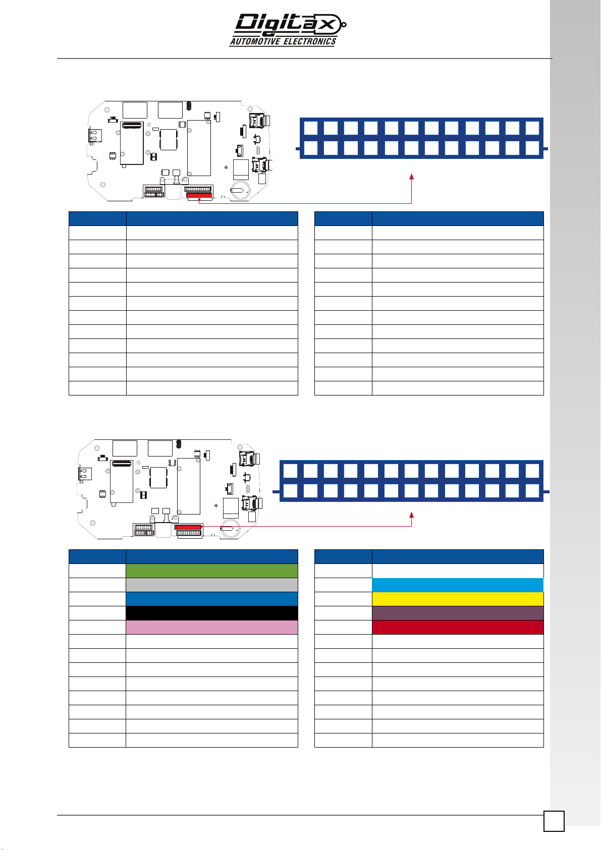
ANDROID
I / O - USB
13
26 25
11
24
10
23
9
22
8
21
7
20
6
19
5
18
4
17
3
16
2
15
12 1
14
PIN FUNCTION PIN FUNCTION
1INPUT 1 14 POWER OUT 1
2INPUT 2 15 POWER OUT 2
3INPUT 3 16 POWER OUT 3
4GND 17 ANALOGIC INPUT 1
5 INPUT 4 18 ANALOG INPUT 2
6 NO CONNECTION 19 EXT. MICROPHONE GND
7 COM 12 - RXD 20 EXT. MICROPHONE INPUT
8 COM 12 - TXD 21 EXT. SPEAKER -
9 GND 22 EXT. SPEAKER +
10 USB 4 - POWER 5V 23 USB 3 - POWER 5V
11 USB 4 - M 24 USB 3 - M
12 USB 4 - P 25 USB 3 - P
13 USB 4 - GND 26 USB 3 - GND
PIN FUNCTION PIN FUNCTION
1 COM 5 - DSR 13 COM 5 - TXD
2 COM 5 - RI 14 COM 5 - RXD
3 COM 5 - DTR 15 COM 5 - RTS
4 COM 8 - TXD 16 COM 5 - CTS
5 COM 8 - RXD 17 COM 5 - DCD
6 GND 18 GND
7 COM 10 - TXD 19 COM 6 - TXD ( 485 Version Data - )
8 COM 10 - RXD 20 COM 6 - RXD (485 Version Data + )
9 GND 21 GND
10 COM 11 - TXD 22 COM 7 - TXD ( 485 Version Data - )
11 COM 11 - RXD 23 COM 7 - RXD (485 Version Data + )
12 GND 24 GND
Mod.
12
24
11
23
10
22
9
21
8
20
7
19
6
18
5
17
4
16
3
15
2
14
1
13
The information contained here are property of DIGITAX Automotive Electronics Italy, and extremely confidential. Any disclosure, copying, distribution to third
party is strictly prohibited.
20
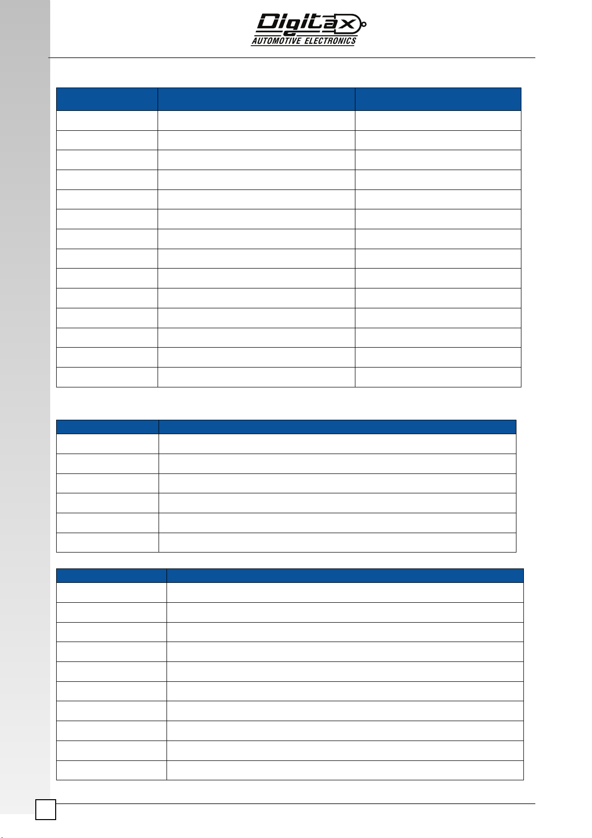
External Serial Ports mapping
Digital Input/Outputs
Outputs
Inputs
Inputs
NAME DESCRIPTION
OGP1 General purpose output 1 (external, refer to pin out/cable chapter)
OGP2 General purpose output 2 (external, refer to pin out/cable chapter)
OGP3 General purpose output 3 (external, refer to pin out/cable chapter)
NAME DESCRIPTION
IGP1 General purpose input 1 (external, refer to pin out/cable chapter)
IGP2 General purpose input 2 (external, refer to pin out/cable chapter)
IGP3 General purpose input 3 (external, refer to pin out/cable chapter)
IGP4 General purpose input 4 (external, refer to pin out/cable chapter)
PANIC INPUT Digital Input for Panic Bu!on. Drive to ground.
ENGINE INPUT Digital Input for engine/igni"on signal, ac"ve high
INPUT SENSOR Digital Input for Passenger Sensor
ANALOG INPUT 1 Generic Analog Input 1, 10 bits ADC
ANALOG INPUT 2 Generic Analog Input 2, 10 bits ADC
TTY XONE ANDROID RS 232 VERSION RS 485 VERSION
TTY-USB 0 COM 7 COM 12
TTY-USB 1 COM 6 COM 11
TTY-USB 2 COM 5 COM 5
TTY-USB 3 COM 8 COM 8
TTY-USB 4 COM 12 COM 7 RS485
TTY-USB 5 COM 11 COM 6 RS485
TTY-USB 6 COM 10 COM 10
Table of contents
Other Digitax Automobile Accessories manuals


Popular Automobile Accessories manuals by other brands

Thule
Thule Kit 1260 Fitting instructions

Witter Towbar Systems
Witter Towbar Systems ZEKAD001CN Fitting instructions

ACV
ACV 381094-19 installation manual

Metra Electronics
Metra Electronics 99-3309B-LC installation instructions

Hauler Racks
Hauler Racks C300 instructions

Haibang
Haibang HA998 Series installation instructions


Thule
Thule 4002XT manual

Toyota
Toyota Verso PZ457-E8566-A0 installation instructions

Lund
Lund Latitude 26510016 manual

Streetwize
Streetwize SWDG3 INFORMATION FOR USE

Star Headlight & Lantern
Star Headlight & Lantern Mini Phantom ULB9 Installation and instruction manual

Lippert
Lippert Tire Linc Installation and owner's manual