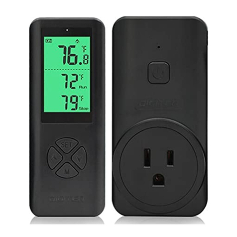
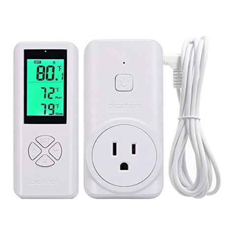
DIGITEN DTC-101 User manual

Manual Index
Features·························································································1
Technical Specications·····································································1
Panel Instructions·············································································2
View Setting Parameters····································································2
Setting Instructions ······································································3
How to change temperature unit ·····················································3
Setup Flow Chart ········································································ 3
Setting the RUN temperature(RV) and STOP temperature(SV) ·············3
Setting Other Functions ································································3
For example ···············································································4
Function range and setting ·································································4
Function Introduction ········································································5
Cooling Mode ·············································································5
Heating Mode ·············································································5
High/Low Temperature Alarm (AH/AL) ·············································5
Time of Compressor Delay Starting (DP)··········································5
Temperature Calibration (CA)·························································6
Display in Fahrenheit or Centigrade unit (CF) ····································6
LCD Backlight Control ·······································································6
Application······················································································6
Troubleshooting ···············································································7
Green LED ash when power on ·························································7
Err Alarm ························································································7
HL Alarm ························································································ 7
Heating and refrigeration equipment don’t work ······································7
WARRANTY····················································································8
WARNING ·····················································································8

-1-
The Thermostat is simple-stage, electronic temperature controller. The large,
lighted LCD screen display is easy to read. The case is designed with reproof
ABS material for human engineering. Temperature sensor is waterproof with
high quality, high-accuracy.
Features
●Large LCD screen
Display the sensed temperature, setting temperature, and custom icons on the
display indicate working mode.
●Support reading with Centigrade or Fahrenheit unit;
●Easy to use and program
Only 2-steps setting for your application, and plug and play design.
●With a temperature correction function
Allow user to adjust measuring accuracy base to on dierent probe, etc.
●Delay starting protection
Protect refrigerating compressor lifetime, avoid compressor to compressor
start frequently.
●High and low temperature alarms are available;
●Over-temperature and sensor fault alarm
Technical Specications
Temperature Control Range -40~120°C, -40~248°F
Temperature Resolution 0.1°C, 0.1°F
Temperature Accuracy ±1°C, ±1°F
Temperature Control Mode Heating and Cooling
Input Power 100~240VAC, 50/60Hz
Temperature Control Output Max.10A/15A, 100-240VAC
Maximum output load DTC-101, 1100W@110V, 2200W@220V;
DTC-151, 1650W@110V, 3300W@220V
Buzzer Alarm High and Low Temperature Alarm
Sensor Type Waterproof NTC sensor (Including)
Sensor Length 2m, 6ft
Relay Contact Capacity DTC-101(10A, 100-240VAC)
DTC-151(15A, 100-240VAC)
Input Power Cable Length 150 cm/5ft
Output Power Cable Length 18cm/7”
Note: The waterproof temperature sensor works with water, seawater, weak
acid or weak base liquid.

-2-
Panel Instructions
1. PV: Current Temperature.
2. RV: Run Temperature
3. SV: Stop Temperature
4. AH: High Temperature Alarm
5. AL: Low Temperature Alarm
6. DP: Time of Compressor Delay Starting
7. CA: Temperature Calibration
8. Mode: Cooling: Working Mode
9. Mode: Heating: Working Mode
View Setting Parameters
When the controller is working normally, short press SET and you can look at
the parameter values in order.

-3-
Setting Instructions
How to change temperature unit
To convert to Fahrenheit unit, press the and buttons simultaneously.
Press them again to return to Celsius unit.
Notice: When temperature unit has been changed, all the setting value will be
recovered to factory settings.
Setup Flow Chart
Setting the RUN temperature(RV) and STOP temperature(SV)
1. Long press the SET button until RV value “ ” ashing.
2. Press and to adjust the temperature value.
3. Press SET button to set SV “ ”.
4. Long press SET button to save and exit.
Note: If no entries are made for 30 seconds while programming is in progress,
the control reverts to the normal temperature display.
Setting Other Functions
To set Low temperature Alarm(AL), High temperature Alarm(AH),
Calibration(CA), Compressor Delay Starting(DP), use the method illustrated

-4-
and outlined below.
1. Long press the SET button until “
” ashing.
2. Press and to adjust the temperature value.
3. Press SET button to set next function.
4. Long press SET button to save and exit.
For example
User want to start cooling equipment when PV=28°C, and stop cooling
equipment when PV=22°C, DP=3 minutes.
1. Long press the SET button until “ ” ashing.
2. Press and to change the run temperature (RV) to 28°C.
3. Press SET button to set “ ” stop temperature (SV).
5. Press and to change the SV to 22°C.
6. Long press SET button to save and exit.
7. Connect the cooling equipment to the outlet.
How to restore default settings
Keep pressing SET key until connect the power to this device, controller
will restore factory setting after BI-BI-BI sound.
Function range and setting
CODE Function Setting Range Default Setting
RV Run Temperature Value -40~120°C 20°C
-40~248°F 68°F
SV Stop Temperature Value -40~120°C 40°C
-40~248°F 104°F
AH High Temperature Alarm -40~120°C 120°C
-40~248°F 248°F
AL Low Temperature Alarm -40~120°C -40°C
-40~248°F -40°F
DP Time of Compressor Delay
Starting 0~10minutes 0
CA Temperature Calibration -15~15°C 0°C
-15~15°F 0°F

-5-
Function Introduction
1.Cooling Mode
Set RV(RUN temperature) > SV(STOP temperature), the temperature
controller enter cooling mode. The LCD will display ,
When PV(measuring temperature) is higher than RV, the cooling
equipment starts working, and run LED will be turned on. When PV(measuring
temperature) reaches to SV(STOP temperature), the cooling equipment stop
working, and stop LED will be turned on.
Note: When run LED is flashing, it means the cooling equipment enter
compressor delay protection function.
2.Heating Mode
Set RV(RUN temperature) < SV(STOP temperature), the temperature
controller enter cooling mode. The LCD will display ,
When PV(measuring temperature) is lower than RV, the heating
equipment starts working, and run LED will be turned on. When PV(measuring
temperature) reaches to SV(STOP temperature), the heating equipment stop
working, and stop LED will be turned on.
3.High/Low Temperature Alarm (AH/AL)
When measuring temperature (PV) ≥ high temperature alarm value (AH),
high temperature alarm will be triggered, buzzer will alarm with tone “bi-bi-Biii”
, press any key to cancel the alarm sound, if user want to close alarm, please
reset the AH value or wait until the PV is lower than AH.
When measuring temperature (PV) ≤ low temperature alarm value (AL),
low temperature alarm will be triggered, buzzer will alarm with tone “bi-bi-Biii”
, press any key to cancel the alarm sound, if user want to close alarm, please
reset the AL value or wait until the PV is more than AL.
4.Time of Compressor Delay Starting (DP)
Under refrigeration mode, after power on, if the measuring temperature (PV)
is higher or equal to Run Temperature (RV), the cooling equipment won’t start
refrigeration immediately, but it will wait for a delay time(DP) to work.
When the time interval between two refrigeration operations is larger than

-6-
preset delay time, the equipment will start refrigeration immediately; when the
time interval between two refrigeration operations is less than preset delay
time, the equipment won’t start refrigeration until achieve the preset delay time.
Delay time will be recorded at the moment that refrigeration stops.
5.Temperature Calibration (CA)
When there is deviation between current temperature and actual temperature,
use temperature calibration function to correct the current temperature and
actual temperature. Corrected Temperature = Temperature (before Calibration)
+Corrected Value (corrected value could be positive value, 0 or negative
value).
6.Display in Fahrenheit or Centigrade unit (CF)
Users can select display with Fahrenheit or Centigrade temperature value
according to their own habit. Default setting is display with Centigrade
temperature value.
LCD Backlight Control
Press and SET buttons simultaneously about 3 seconds until the symbol
disappears, the LCD light will shut o automatically after 30 seconds.
Press and SET buttons simultaneously about 3 seconds until the LCD
appears , the LCD will be stay on.
Application
The thermostat can be used to control a wide variety of dual-stage refrigeration
and heating, or HVAC equipment. Typical applications include:
●Retail store display freezers and coolers
●Supermarket display cases for product/meats
●Retail store walk-in freezers and coolers
●Boiler operating control
●Condenser fan cycling or staging
●Cooling tower pump and fan control
●Space and return air temperature control
●Aquarium water temperature
●BBQ
●Over temperature control/protection

-7-
Troubleshooting
If you have a problem with thermostat, there’s usually a quick and simple
solution.
Green LED ash when power on
It is a normal phenomenon, Delay Starting Protection function for Refrigerating
Compressor is working. you could enter Setup Mode directly, or wait 3
minutes(base on DP setting value) until it doesn’t flash green light before
setting the temperature controller.
Err Alarm
When temperature sensor is in short-circuited or open-circuited, the controller
will prompt sensor fault mode, and the buzzer will alarm, and LED displays
Err. Buzzer alarm could be dismissed by pressing any key. After faults solved,
the system will return to normal working mode. So make sure that the sensor
is plugged into the hole fully, if it still displays Err, you can change another
sensor.
HL Alarm
When current temperature exceeds the measuring range (less than -40°C /-40°
F or higher than 120 °C/248 ° F), the controller will prompt over-temperature
alarm mode, and cancel all the actions. The buzzer will alarm, LED displays
HL. Buzzer alarm could be dismissed by pressing any key. When temperature
returns to measuring range, the system will return to normal working status.
Heating and refrigeration equipment don’t work
1.Please make sure the setting value is correct. If thermostat works ne, the
green LED(RUN) is on.
2.Please check if the loading is contacted reversely to heating or cooling
outlet.
If thermostat does not operate properly after trying the troubleshooting steps,

-8-
WARRANTY
The DIGITEN products are guaranteed to the original owner for one year
against defects in workmanship and materials. Please contact us:
www.digit-en.com/support
WARNING
Do Not Overload
This unit works with load up to 10A(DTC-101) / 15A(DTC-151). If load is larger
than rated value, it would become very hot even burn the thermostat. That is
very dangerous. It is best that the load is less than or equal to 7A(DTC-101)
/ 12A(DTC-151), if you require the temperature controller to work stably for a
long term.
The probe is waterproof, but controller is not waterproof, so don’t get water
into the controller and outlet.
COPYRIGHT 2020 DIGITEN CO., LTD ALL REIGHTS RESERVED
This manual suits for next models
1
Table of contents
Other DIGITEN Thermostat manuals

