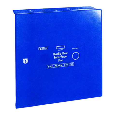
DIGITIZE Q-MUX User manual

Q-MUX
MULTIPLEX SYSTEM
Digitize, Inc.
158 Edison Road
Lake Hopatcong, New Jersey 0 849
Tel: (9 3) 663-1011 Part Number: 00226-0001
Fax: (9 3) 663-4333 Revision: F
Website: http://www.digitize-inc.com

Digitize, Inc.
158 Edison Road
Lake Hopatcong, NJ 0 849-221
The Digitize logo (stylized) is a registered trademark of Digitize, Inc.

PROPRIETARY NOTICE
AND
DISCLAIMER
DIGITIZE, INC.
158 EDISON ROAD
LAKE HOPATCONG, NJ 0 849-221
PH: (9 3) 663-1011
FAX: (9 3) 663-4333
E-Mail: info@digitize-inc.com
Website: http://www.digitize-inc.com
This manual has been prepared by DIGITIZE, INC. for use by its licensees, distributors and
customers. The information contained herein is the property of DIGITIZE, INC. and may not
be copied, disclosed or reproduced, in whole or in part, without the prior written approval of
DIGITIZE, INC. Any unauthorized disclosure to, or use of the enclosed information by,
unauthorized third persons shall void any and all representations, warranties and obligations
on the part of DIGITIZE, INC.
DIGITIZE, INC. reserves the right to make changes to the specifications and material
contained herein without prior notice. The information and/or examples (including, but not
limited to circuitry, wiring diagrams, programming, the operation or use shown) described in
this manual are intended solely to illustrate the operating principles of the particular product.
They are not a warranty, representation or guarantee that a particular example or use shown
will perform in a particular situation. They are given for illustration purposes only.
DIGITIZE, INC. shall not be responsible, nor does it represent, that any example of
illustration will perform in a particular environment or practice unless it specifically makes a
representation to that effect.
The material set forth herein is for informational ur oses only, and
DIGITIZE, INC. assumes no atent liability with res ect to any information or
illustrations contained herein.


Table of Contents
1 What is the Q-Mux System?.....................................................................1-1
2 Components of a Q-Mux System .............................................................2-1
2.1 Q-EOL End-of-Line IDM ................................................................................................................. 2-1
2.2 Q-1C, Digital Input IDM................................................................................................................... 2-2
2.3 Q-1CL, Latched Input IDM .............................................................................................................. 2-3
2.4 Q-1R, Relay Output IDM.................................................................................................................. 2-4
2.5 Q-I/O, Input/Output IDM.................................................................................................................. 2-5
2.6 Q-SNP-EOL-O/C IDM ..................................................................................................................... 2-6
2. Q-SNP-RLY-FORM C IDM............................................................................................................. 2-
2.8 Q-SNP-TRIPLE IDM Mother Board ................................................................................................ 2-8
2.9 Q-SNP-16 IDM Mother Board.......................................................................................................... 2-9
2.10 Dual EOL IDM ............................................................................................................................. 2-10
2.11 EOL / Relay IDM.......................................................................................................................... 2-11
2.12 Q-Node Controller ........................................................................................................................ 2-12
2.13 Q-Mux IDM Programmer ............................................................................................................. 2-14
2.14 Q-Mux Node Utility Software....................................................................................................... 2-15
3 Considerations for a Q-Mux System ........................................................3-1
3.1 Type of Inputs Required.................................................................................................................... 3-1
3.2 Is Additional Power required when using Output IDMs? ................................................................. 3-1
3.3 Wire Type & Length ......................................................................................................................... 3-1
3.4 What is the Q-Node going to placed in and how will it be powered? ............................................... 3-2
3.5 Transient Protection .......................................................................................................................... 3-2
4 Setting up the 3505 Hardware ..................................................................4-1
4.1 Q-Mux Software Option ................................................................................................................... 4-1
4.2 RS-485 Configurator Bd ................................................................................................................... 4-1
4.3 RS-485 Line Driver Board and Rack ................................................................................................ 4-2
5 Setting up the 3505 Firmware...................................................................5-1
5.1 Password ........................................................................................................................................... 5-1
5.2 Setup Screen...................................................................................................................................... 5-2
5.2.1 Set Node Address....................................................................................................................... 5-2
5.2.2 Add/Chg/Del ID......................................................................................................................... 5-3
5.2.3 Set Tamper use .......................................................................................................................... 5-6
6 Getting the System Up and Running ........................................................6-1
Advanced Settings & Options .................................................................. -1
.1 Coded Output Capability................................................................................................................... -1
8 Trouble Shooting the Q-Mux....................................................................8-1
8.1 Questions to ask before Starting?...................................................................................................... 8-1
8.2 3505 Issues........................................................................................................................................ 8-1
8.3 Node Issues ....................................................................................................................................... 8-1
8.4 IDM Issues ........................................................................................................................................ 8-2
9 What is the Mystery Symbol?...................................................................9-1
10 Appendix A...........................................................................................10-1


00226-0001 Rev. F 05/11 1-1
1 What is the Q-Mux System?
Ty ical Q-Mux IDM
The Q-Mux is a low cost multiplex system. Two wires are used to power and communicate
serially to the ID modules (IDMs). Commands from the Q-Node to the ID modules take the
form of modulating the Buss voltages between 0 and 10v. The data returned from the
modules is in the form of increased Buss current. Each Q-node can control up to 99
mix/matched ID modules. Up to 32 Q-Nodes may be used in one system. Total range of the
Q-Mux system is 5,000 feet from the System 3505 to the last Q-Node and up to 5,000 feet
from the Q-Node to the last ID module. ID modules may be set to any address from 1 to 99.
Addresses are stored on an internal EEPROM and can be changed by the Q-Mux
Programmer.
Basic Com onents of a Q-Mux System.

What is the Q-Mux System? Digitize Inc.
1-2 00226-0001 Rev. F 05/11
The key components of the Q-Mux system are:
IDMs – ID modules are placed remotely in the field and communicate over a pair of
wires (TBUSS) with a Q-Mux Node controller. The IDM’s are powered by the same
wires it uses to communicate. Many different types of ID modules are available with both
input and output capabilities. The Q-Mux system is designed so that as many 99 IDM’s
can be connected on the same pair of wires (TBUSS).
TBUSS – The pair of wires extending from an Q-Node out to the field where the IDM’s
are remotely located. The TBUSS is low voltage and current limited. It both powers the
remote IDMs and is used to communicate with the IDMs.
Q-Node Controller- The Q-Node Controller creates the signals necessary to
communicate with the IDMs on a pair of ordinary wires.
Q-Mux Programmer – The Q-Mux Programmer is used to assign an ID number to each
of the IDM placed on a TBUSS.
Q-Mux Node Utility Software - Q-Mux Utility Software is a Q-Node diagnostic and
address PC utility. The software allows the user to test Q-Mux Nodes and Input or Output
devices connected to it from their computer and assign node addresses to the Q-Mux
Nodes.
Other items that are discussed are:
Style 3 – Term for a connection between the System 3505 and the Q-Nodes. This connection
is simply a pair of wires that connect the System 3505 to the Q-Nodes. The connection is
supervised at the System 3505, but a single break in the wires could interrupt communication
to the Q-Nodes.
Style 6 - Term for a connection between the System 3505 and the Q-Nodes. The System
3505 communicates with the Q-Nodes over two pairs of wires that forms a large loop. This is
an improved method of connecting the System 3505 to the Q-Nodes in that a single break
anywhere in the wires does not interrupt the communication to the System 3505. This
connection is also supervised and any break will be annunciated on the System 3505.

00226-0001 Rev. F 05/11 2-1
2 Components of a Q-Mux System
2.1 Q-EOL End-of-Line IDM
The Q-EOL IDM provides a direct interface between variable resistance inputs and the Q-
Node controller. The module is used to monitor fire alarm and security devices. A 1.43K
Ohm EOL resistor is included with the Q-EOL module.
Diagram of Q-EOL IDM
Digitize Part Number:
425182-0006
Dimensions:
1. 5in. long x .3 5 in. dia., 6” lead length
Power Requirements:
15 VDC @ 10 milliamps max.
Operating Environment:
Install in a dry, indoor environment.
Operating Temperature:
32°F-165°F
Operating Humidity:
0-95%, non-condensing
Approvals:
ETL Approved
What is this?? See Section 9.

Components Digitize Inc.
2-2 00226-0001 Rev. F 05/11
2.2 Q-1C, Digital In ut IDM
The Q-1C IDM is a transponder compatible with Digitize’s Q-Mux multiplex system. The
module provides a direct interface between digital inputs and the Q-Mux Node controller.
The four-wire module connects to the TBuss (2-wires) and to the contact that is to be
monitored (2 wires). Any floating contact can be read by the Q-1C. The design eliminates
the limitation of gold-plated contacts.
Diagram of Q-1C IDM
Digitize Part Number:
425182-0008
Dimensions:
1. 5in. long x .3 5 in. dia., 6” lead length
Power Requirements:
15 VDC @ 10 milliamps max.
Operating Environment:
Install in a dry, indoor environment.
Operating Temperature:
32°F-165°F
Operating Humidity:
0-95%, non-condensing
Approvals:
ETL Approved
What is this?? See Section 9.

Components Digitize Inc.
00226-0001 Rev. F 05/11 2-3
2.3 Q-1CL, Latched In ut IDM
The Q-1C and Q-1CL IDMs provide a direct interface between digital inputs and the Q-Mux
controller. The Q-1C module can be programmed at the System 3505 to respond to normally
open (NO) or normally closed (NC) inputs.
Any floating contact can be read by the Q-1C. A momentary input is latched by the Q-1CL
until read and reset by the System 3505. The Q-1CL emulates the response of the standard,
real-time Q-1C module. The external contact is connected to an internal latch in the Q-1CL.
The Q-1CL can interface directly with fast acting momentary dry contacts.
Diagram of Q-1CL IDM
Digitize Part Number:
425182-0003
Dimensions:
1. 5in. long x .3 5 in. dia., 6” lead length
Power Requirements:
15 VDC @ 10 milliamps max.
Operating Environment:
Install in a dry, indoor environment.
Operating Temperature:
32°F-165°F
Operating Humidity:
0-95%, non-condensing
Approvals:
ETL Approved
What is this?? See Section 9.

Components Digitize Inc.
2-4 00226-0001 Rev. F 05/11
2.4 Q-1R, Relay Out ut IDM
The Q-1R IDM provides a NO relay contact output under control of the Q-Node controller.
A contact monitoring signal is sent back to the System 3505* indicating relay contact open,
relay contact closed, or trouble (malfunction).
Diagram of Q-1R IDM
Digitize Part Number:
425182-0004
Dimensions:
2. 5in. x 2. 5in. x 1.5in; Open PCB
Power Requirements:
15 VDC @ 10 milliamps max.
Contact Rating:
8 Amps @ 250 VAC
Operating Environment:
Install in a dry, indoor environment.
Operating Temperature:
32°F-165°F
Operating Humidity:
0-95%, non-condensing
Approvals:
ETL Approved
What is this?? See Section 9.

Components Digitize Inc.
00226-0001 Rev. F 05/11 2-5
2.5 Q-I/O, In ut/Out ut IDM
The Q-I/O IDM provides a direct interface between digital inputs (contact closures) and he
Q-Mux controller. It also provides a digital output that can be used to turn on/off an LED
indicator. Power to the LED can either be provided from the TBuss (with some limitations),
or from an external power supply.
Diagram of Q-I/O IDM
Digitize Part Number:
425182-0001
Dimensions:
1. 5in. long x .3 5 in. dia., 6” lead length
Power Requirements:
15 VDC @ 10 milliamps max.
Output Rating:
1 VDC @ 30 milliamps max.
Operating Environment:
Install in a dry, indoor environment.
Operating Temperature:
32°F-165°F
Operating Humidity:
0-95%, non-condensing
Approvals:
ETL Approved
What is this?? See Section 9.

Components Digitize Inc.
2-6 00226-0001 Rev. F 05/11
2.6 Q-SNP-EOL-O/C IDM
The Q-SNP-EOL-O/C is a Q-EOL IDM on an open printed circuit board. It is designed to be
connected to the Q-SNP Mother boards. The “Q-SNP” design allows the IDMs to easily be
added, changed, and removed from an installation. The Mother board is ordered separately.
The Q-EOL module provides a direct interface between variable resistance inputs and the Q-
Mux controller. The module is used to monitor fire alarm and security devices. A 1.43K
Ohm EOL resistor is included with the Q-EOL module. The IDM also has an open collector
output for controlling small loads such as leds.
To View of Q-SNP-EOL-OC Bd.
Diagram of Q-SNP-EOL-OC with a Mother Bds
Digitize Part Number:
425182-0009
Dimensions:
1. 5in. x .53in.; Open PCB
Power Requirements:
15 VDC @ 10 milliamps max.
Operating Environment:
Install in a dry, indoor environment.
Operating Temperature:
32°F-165°F
Operating Humidity:
0-95%, non-condensing
Approvals:
ETL Approved

Components Digitize Inc.
00226-0001 Rev. F 05/11 2-
2.7 Q-SNP-RLY-FORM C IDM
The Q-SNP-RLY-FORM C is a Q—1R IDM on an open printed circuit board. It is designed
to be connected to the Q-SNP Mother boards. The “Q-SNP” design allows the IDMs to
easily be added, changed, and removed from an installation. The Mother board is ordered
separately.
Module Q-SNP-RLY-FORM C provides a Form C (NO/COM/NC) relay contact output
under control of the Q-Mux™ Central Buss Driver. A contact monitoring signal is sent back
to the System 3505* indicating relay contact open, relay contact closed, or trouble
(malfunction).
To View and Diagram of Q-SNP-RLY FORM C Bd.
Digitize Part Number:
425182-0010
Dimensions:
1. 5 in. x . 5 in.; Open PCB.
Power Requirements:
15 VDC @ 10 milliamps max.
Operating Environment:
Install in a dry, indoor environment.
Operating Temperature:
32°F-165°F
Operating Humidity:
0-95%, non-condensing
Approvals:
ETL Approved

Components Digitize Inc.
2-8 00226-0001 Rev. F 05/11
2.8 Q-SNP-TRIPLE IDM Mother Board
The Q-SNP-TRIPLE IDM MOTHER BOARD holds up to three Q-SNP-EOL or Q-SNP-
RLY IDM boards. The board is designed to fit inside a standard 4x4 electrical box. Each
SNP board has an input/output removable connector and Led. An additional removable
connector is provided for the connection to the TBUSS.
The boards shown above have three SNP-EOL bds installed.
(SNP-EOL bds not included. Ordered separately.)
Digitize Part Number:
425182-0012
Dimensions:
3.22” x 2.69”; Open PCB. Mounting holes are 2.13” x 2.3 ”.
Leds:
Each SNP board has an Led mounted on the Mother Bd.
Operating Environment:
Install in a dry, indoor environment.
Operating Temperature:
32°F-165°F
Operating Humidity:
0-95%, non-condensing
What is this?? See Section 9.

Components Digitize Inc.
00226-0001 Rev. F 05/11 2-9
2.9 Q-SNP-16 IDM Mother Board
The Q-SNP-16 MOTHER BOARD holds up to sixteen Q-SNP-EOL or Q-SNP-RLY IDM
boards. The panel is designed for a standard 19” rack mount. Each SNP board has an
input/output removable connector and an on board Led. An additional removable connector
is provided for the connection to the TBUSS and external +12v power supply.
The board shown above has 16 SNP-EOL bds installed.
(SNP-EOL bds not included. Ordered separately.)
Digitize Part Number:
425182-0011
Dimensions:
3.50” x 19.00”; Open PCB mounted on sheetmetal.
Leds:
Each SNP board has an Led mounted on the Mother Bd.
Operating Environment:
Install in a dry, indoor environment.
Operating Temperature:
32°F-165°F
Operating Humidity:
0-95%, non-condensing
What is this?? See Section 9.

Components Digitize Inc.
2-10 00226-0001 Rev. F 05/11
2.10 Dual EOL IDM
The Dual EOL IDM Board is basically two EOL IDM boards combined on one open printed
circuit board.
Each EOL module provides a direct interface between variable resistance inputs and the Q-
Mux controller. The module is used to monitor fire alarm and security devices. A 1.43K
Ohm EOL resistor is included with each of the two Q-EOL modules.
Photo and Diagram of a Dual EOL IDM Bd.
Digitize Part Number:
02-4033
Dimensions:
2.69 in. x 3.21in.; Open PCB. Mounting holes are 2.13” x 2.3 ”
Power Requirements:
15 VDC @ 20 milliamps max. if both EOL IDMs are used.
Operating Environment:
Install in a dry, indoor environment.
Operating Temperature:
32°F-165°F
Operating Humidity:
0-95%, non-condensing
Approvals:
ETL Approved
What is this?? See Section 9.

Components Digitize Inc.
00226-0001 Rev. F 05/11 2-11
2.11 EOL / Relay IDM
The EOL / RELAY IDM Board is basically an EOL IDM combined with an RELAY IDM
on one open printed circuit board.
Photo and Diagram of an EOL / RELAY IDM Bds
Digitize Part Number:
02-4032
Dimensions:
2.69 in. x 3.21in.; Open PCB. Mounting holes are 2.13” x 2.3 ”
Power Requirements:
15 VDC @ 20 milliamps max. if both EOL IDMs are used.
Operating Environment:
Install in a dry, indoor environment.
Operating Temperature:
32°F-165°F
Operating Humidity:
0-95%, non-condensing
Approvals:
ETL Approved
What is this?? See Section 9.

Components Digitize Inc.
2-12 00226-0001 Rev. F 05/11
2.12 Q-Node Controller
The Q-Node is a microprocessor based central polling controller Buss interface. The Q-Node
drives the Multiplex loop, and communicates with the modules along the buss. It
communicates with the master controller through RS-485 serial port communication.
The Q-Node sends commands to, and receives data from, the ID modules. In turn, it sends
the data to, and receives commands from the System 3505. Up to 32 Q-Nodes may be
installed in one system. Total wire run from the System 3505 to the last Q-Node is 5,000 ft.
with 18 AWG.
The Q-Node can be set to any address from 1-32. The address is stored internally in an
EEPROM. It is shipped pre-programmed to address #1. The field should reserve address #1
for use on the last Q-Node.
The Q-Node address is programmed using the Q-Mux Utility Software. See Section 2.14.
Layout & Diagram of Q-Node Controller
Table of contents
Other DIGITIZE Control Unit manuals
Popular Control Unit manuals by other brands

FONESTAR
FONESTAR ZS-1112R instruction manual

claber
claber meteo 8323 manual

Rheem
Rheem Raypak TempTracker MOD+ HYBRID Installation and operation instruction

Xylem
Xylem SI Analytics TITRATOR TitroLine 7500 KF operating instructions

salmson
salmson Cleanskid Series Installation and starting instructions

Metso
Metso L12 Series Installation maintenance and operating instructions

Eaton
Eaton Series NRX installation instructions

Espressif
Espressif PAN100 manual

Telit Wireless Solutions
Telit Wireless Solutions GC864 Series Hardware user's guide

Gebwell
Gebwell G-Power 2/100 Installation and maintenance manual

TEGO
TEGO Roundline Master quick start guide

Lincoln industrial
Lincoln industrial MP1 owner's manual