IFM CR3020 Owner's manual

1
dh
Original Programming Manual (Supplement)
CAN Module Real Time Clock (RTC)
CR3020
V02
CODESYS®> V2.3.9.33
English
7391087_01_UK 2017-10-26

2
ifm Programming Manual (supplement) CAN module RTC CR3020 2017-10-26
Contents
Contents
1About this manual 3
1.1 Copyright..............................................................................................................................3
1.2 What do the symbols and formats mean? ...........................................................................4
1.3 How is this documentation structured?................................................................................5
2System description 6
2.1 Information about the device................................................................................................6
2.2 Overview of functions...........................................................................................................6
2.3 Hardware description...........................................................................................................7
2.4 Interface description.............................................................................................................8
2.4.1 CAN interfaces.............................................................................................................................8
2.5 Software description ............................................................................................................9
2.5.1 CAN messages via COB-ID and node ID.....................................................................................9
3ifm function elements 12
3.1 ifm libraries for the device CRnnnn....................................................................................12
3.1.1 Library ifm_RTC_Basic_V02yyzz.LIB.........................................................................................12
3.1.2 Library ifm_RTC_Classicx_V02yyzz.LIB....................................................................................13
3.2 ifm functional elements, POUs (Basic) ..............................................................................14
3.2.1 CONCAT_DATE_TIME..............................................................................................................15
3.2.2 RTC_INITIALIZE ........................................................................................................................16
3.2.3 RTC_SET...................................................................................................................................17
3.2.4 RTC_REQUEST.........................................................................................................................19
3.2.5 RTC_SET_ALARM.....................................................................................................................21
3.2.6 RTC_REQUEST_ALARM ..........................................................................................................23
3.3 ifm functional elements, POUs (Classic) ...........................................................................25
3.3.1 CONCAT_DATE_TIME..............................................................................................................26
3.3.2 RTC_INITIALIZE ........................................................................................................................27
3.3.3 RTC_SET...................................................................................................................................29
3.3.4 RTC_REQUEST.........................................................................................................................31
3.3.5 RTC_SET_ALARM.....................................................................................................................33
3.3.6 RTC_REQUEST_ALARM ..........................................................................................................35
4Glossary of Terms 37
5Index 50
6Notizen • Notes • Notes 52
7ifm weltweit • ifm worldwide • ifm à l’échelle internationale 55
3
ifm Programming Manual (supplement) CAN module RTC CR3020 2017-10-26
About this manual Copyright
1About this manual
Copyright ............................................................................................................................................... 3
What do the symbols and formats mean?............................................................................................. 4
How is this documentation structured? ................................................................................................. 5
202
>
1.1 Copyright
6088
© All rights reserved by ifm electronic gmbh. No part of this manual may be reproduced and used
without the consent of ifm electronic gmbh.
All product names, pictures, companies or other brands used on our pages are the property of the respective rights owners:
• AS-i is the property of the AS-International Association, (→www.as-interface.net)
• CAN is the property of the CiA (CAN in Automation e.V.), Germany (→www.can-cia.org)
• CODESYS™ is the property of the 3S – Smart Software Solutions GmbH, Germany (→www.codesys.com)
• DeviceNet™ is the property of the ODVA™ (Open DeviceNet Vendor Association), USA (→ www.odva.org)
• EtherNet/IP® is the property of the →ODVA™
• EtherCAT®is a registered trade mark and patented technology, licensed by Beckhoff Automation GmbH, Germany
• IO-Link®(→www.io-link.com) is the property of the →PROFIBUS Nutzerorganisation e.V., Germany
• ISOBUS is the property of the AEF – Agricultural Industry Electronics Foundation e.V., Deutschland
(→www.aef-online.org)
• Microsoft®is the property of the Microsoft Corporation, USA (→www.microsoft.com)
• PROFIBUS®is the property of the PROFIBUS Nutzerorganisation e.V., Germany (→www.profibus.com)
• PROFINET®is the property of the →PROFIBUS Nutzerorganisation e.V., Germany
• Windows®is the property of the →Microsoft Corporation, USA

4
ifm Programming Manual (supplement) CAN module RTC CR3020 2017-10-26
About this manual What do the symbols and formats mean?
>
1.2 What do the symbols and formats mean?
203
The following symbols or pictograms illustrate the notes in our instructions:
WARNING
Death or serious irreversible injuries may result.
CAUTION
Slight reversible injuries may result.
NOTICE
Property damage is to be expected or may result.
Important note
Non-compliance can result in malfunction or interference
Information
Supplementary note
►...
Request for action
>...
Reaction, result
→...
"see"
abc
Cross-reference
123
0x123
0b010
Decimal number
Hexadecimal number
Binary number
[...]
Designation of pushbuttons, buttons or indications

5
ifm Programming Manual (supplement) CAN module RTC CR3020 2017-10-26
About this manual How is this documentation structured?
>
1.3 How is this documentation structured?
204
1508
This documentation is a combination of different types of manuals. It is for beginners and also a
reference for advanced users. This document is addressed to the programmers of the applications.
How to use this manual:
Refer to the table of contents to select a specific subject.
Using the index you can also quickly find a term you are looking for.
At the beginning of a chapter we will give you a brief overview of its contents.
Abbreviations and technical terms →Appendix.
In case of malfunctions or uncertainties please contact the manufacturer at:
Contact →ifm weltweit • ifm worldwide • ifm à l’échelle internationale (→p. 55)
We want to become even better! Each separate section has an identification number in the top right
corner. If you want to inform us about any inconsistencies, indicate this number with the title and the
language of this documentation. Thank you very much for your support!
We reserve the right to make alterations which can result in a change of contents of the
documentation. You can find the current version on ifm's website:
→ifm weltweit • ifm worldwide • ifm à l’échelle internationale (→p. 55)
>

6
ifm Programming Manual (supplement) CAN module RTC CR3020 2017-10-26
System description Information about the device
2System description
Information about the device................................................................................................................. 6
Overview of functions............................................................................................................................ 6
Hardware description............................................................................................................................. 7
Interface description.............................................................................................................................. 8
Software description.............................................................................................................................. 9
975
>
2.1 Information about the device
21798
This manual describes of the ecomatmobile family for mobile machines of ifm electronic gmbh:
Real-time clock (RTC) CR3020
>
2.2 Overview of functions
21808
Only ONE real-time clock may be installed in each project!
The real-time clock (RTC) offers the following functions:
Initialisation of the real-time clock,
Adjustment of the CAN baud rate to the controller
Setting of time and date:
Calendar day, month, year, hour, minute day of the week
Setting of date for the alarm output:
days, hours minutes (max. 7 days, 23 hours, 59 minutes)
Requesting current time and current date:
calendar day, month, year, hour, minute, day of the week, battery charging status
Requesting the remaining time till the set alarm:
days, hours, minutes
The real-time clock can be configured and consulted in various ways:
in conjunction with a controller from ifm-ecomatmobile
this is what POUs in a CODESYS library are there for
→chapter Functional elements from ifm (→p. 12)
in conjunction with a controller that is not from ifm
for this CAN messages via COB-ID and node ID are used
→chapter CAN messages via COB-ID and node ID (→p. 9)

7
ifm Programming Manual (supplement) CAN module RTC CR3020 2017-10-26
System description Hardware description
>
2.3 Hardware description
21800
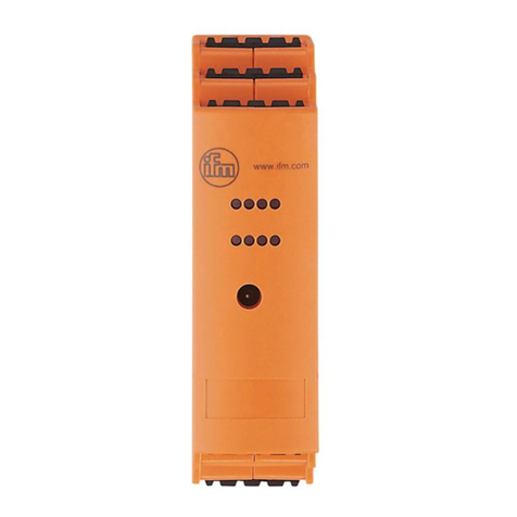
The CR3020 module is a real-time clock (RTC) for CAN systems.
Housing
Automotive relay housing
Connections
CAN Layer 2
Voltage supply
1 binary output
for automotive relay bases
Details →Data sheet

8
ifm Programming Manual (supplement) CAN module RTC CR3020 2017-10-26
System description Interface description
>
2.4 Interface description
CAN interfaces ...................................................................................................................................... 8
14098
>
2.4.1 CAN interfaces
CAN: Interfaces and protocols .............................................................................................................. 8
14101
Connections and data →data sheet
>
CAN: Interfaces and protocols
21803
21804
The device is equipped with one CAN interface only.
The interface can generally be used in combination with the following functions:
• RAW-CAN (Layer 2): CAN at level 2

9
ifm Programming Manual (supplement) CAN module RTC CR3020 2017-10-26
System description Software description
>
2.5 Software description
CAN messages via COB-ID and node ID.............................................................................................. 9
21807
►The CODESYS libraries of version 2 are absolutely required.
>
2.5.1 CAN messages via COB-ID and node ID
Initialise real-time clock (RTC) .............................................................................................................. 9
Define time and date ........................................................................................................................... 10
Request time and date ........................................................................................................................ 10
Define alarm date................................................................................................................................ 11
Request the remaining time till the alarm............................................................................................ 11
21810
Choose this method if you do not configure or consult the real-time clock with an ifm controller (RTC).
>
Initialise real-time clock (RTC)
21811
This must be the first communication with the real-time clock (RTC)!
RTC_INITIALIZE
Initialise the real-time clock (RTC) in the CAN system:
Message to the real-time clock:
COB ID
Message
Notes
0x7FF
DLC = 0
no data bytes available at DLC=0
The real-time clock (RTC) adjusts the baud rate on your CAN interface to the baud rate of the sending
controller.
Response of the real-time clock:
COB ID
Message
Notes
0x7FE
DLC = 1
Byte 0 = distinct node ID
---

10
ifm Programming Manual (supplement) CAN module RTC CR3020 2017-10-26
System description Software description
>
Define time and date
21812
RTC_SET
Set the real-time clock to the current time and the current date:
Message to the real-time clock:
COB ID
Message
Notes
0x300 + node ID
DLC = 6
Byte 0 = calendar day
Byte 1 = month
Byte 2 = year
Byte 3 = hour
Byte 4 = minute
Byte 5 = day of the week
---
The real-time clock sets the internal value for second to zero.
Response of the real-time clock:
COB ID
Message
Notes
0x280 + node ID
DLC = 6
Byte 0 = calendar day
Byte 1 = month
Byte 2 = year
Byte 3 = hour
Byte 4 = minute
Byte 5 = day of the week
---
>
Request time and date
21815
RTC_REQUEST
Request the current time and the current date:
Message to the real-time clock:
COB ID
Message
Notes
0x200 + node ID
DLC = 0
no data bytes available at DLC=0
Response of the real-time clock:
COB ID
Message
Notes
0x180 + node ID
DLC = 8
Byte 0 = calendar day
Byte 1 = month
Byte 2 = year
Byte 3 = hour
Byte 4 = minute
Byte 5 = seconds
Byte 6 = day of the week
Byte 7 = battery charging level
Battery charging level
0 = sufficient
1 = too low

11
ifm Programming Manual (supplement) CAN module RTC CR3020 2017-10-26
System description Software description
>
Define alarm date
21813
RTC_SET_ALARM
Define the date on which the alarm output of the real-time clock (RTC) is to be set:
(max. target time till the alarm: 7 days, 23 hours, 59 minutes)
Message to the real-time clock:
COB ID
Message
Notes
0x500 + node ID
DLC = 6
Byte 0 = target time till the alarm: days (max. 7)
Byte 1 = target time till the alarm: hours (max. 23)
Byte 2 = target time till the alarm: minutes (max. 59)
Byte 3 = (new) node ID
Byte 4 = (new) node ID
Byte 5 = (new) baud rate
If required: change the node ID of the real-
time clock: max. value = 0x3F
byte 5 = 02 baud rate = 500 kBd
byte 5 = 03 baud rate = 250 kBd
byte 5 = 04 baud rate = 125 kBd
The real-time clock (RTC) sets the internal value for the second to zero.
Response of the real-time clock:
COB ID
Message
Notes
0x480 + node ID
DLC = 6
Byte 0 = target time till the alarm: days
Byte 1 = target time till the alarm: hours
Byte 2 = target time till the alarm: minutes
Byte 3 = (new) node ID
Byte 4 = (new) node ID
Byte 5 = (new) baud rate
---
>
Request the remaining time till the alarm
21816
RTC_REQUEST_ALARM
Request the remaining time till the setting of the alarm output:
Message to the real-time clock:
COB ID
Message
Notes
0x400 + node ID
DLC = 0
no data bytes available at DLC=0
Response of the real-time clock:
COB ID
Message
Notes
0x380 + node ID
DLC = 6
Byte 0 = remaining time in days
Byte 1 = remaining time in hours
Byte 2 = Remaining time in minutes
Byte 3 = node ID
Byte 4 = node ID
Byte 5 = (new) baud rate
Byte 5 = 02 baud rate = 500 kBd
Byte 5 = 03 baud rate = 250 kBd
Byte 5 = 04 baud rate = 125 kBd
>

12
ifm Programming Manual (supplement) CAN module RTC CR3020 2017-10-26
ifm function elements ifm libraries for the device CRnnnn
3ifm function elements
ifm libraries for the device CRnnnn..................................................................................................... 12
ifm functional elements, POUs (Basic)................................................................................................ 14
ifm functional elements, POUs (Classic)............................................................................................. 25
13586
All CODESYS function elements (FBs, PRGs, FUNs) are stored in libraries. Below you will find a list of
all the ifm libraries you can use with this device.
This is followed by a description of the function elements, sorted by topic.
>
3.1 ifm libraries for the device CRnnnn
Library ifm_RTC_Basic_V02yyzz.LIB ................................................................................................. 12
Library ifm_RTC_Classicx_V02yyzz.LIB............................................................................................. 13
14235
>
3.1.1 Library ifm_RTC_Basic_V02yyzz.LIB
21827
Only ONE real-time clock may be installed in each project!
The POUs of this library are designed for the following ifm devices:
• BasicController: CR040n, CR041n, CR043n
• BasicDisplay: CR045n
• SmartController: CR253n
This ifm library contains the following function blocks:
Function element
Short description
CONCAT_DATE_TIME (→p. 14)
converts the received data that describe the time and the date from bytes into coherent strings
RTC_INITIALIZE (→p. 16)
initialises the connection between the controller and the real-time clock
RTC_REQUEST (→p. 19)
initialises the connection between the controller and the real-time clock
RTC_REQUEST_ALARM (→p. 23)
asks the real-time clock about the following current values:
• the remaining time till the setting of the alarm output
• the current node ID
RTC_SET (→p. 17)
Set new time, date and day of the week of the real-time clock
RTC_SET_ALARM (→p. 21)
configures the delay after which the real-time clock sets the alarm output

13
ifm Programming Manual (supplement) CAN module RTC CR3020 2017-10-26
ifm function elements ifm libraries for the device CRnnnn
>
3.1.2 Library ifm_RTC_Classicx_V02yyzz.LIB
21828
x = 1...4 = number of the CAN interface (depending on the device, →data sheet)
Only ONE real-time clock may be installed in each project!
The POUs of this library are designed for the following ifm devices:
• ClassicController: CR00nn, CR05nn
• CabinetController: CR03nn
• ExtendedController: CR01nn, CR02nn
• SmartController: CR250n
• SafetyController: CR7nnn
• PDMsmart: CR107n
This ifm library contains the following function blocks:
Function element
Short description
CONCAT_DATE_TIME (→p. 14)
converts the received data that describe the time and the date from bytes into coherent strings
RTC_INITIALIZE (→p. 27)
initialises the connection between the controller and the real-time clock
RTC_REQUEST (→p. 31)
initialises the connection between the controller and the real-time clock
RTC_REQUEST_ALARM (→p. 35)
asks the real-time clock about the following current values:
• the remaining time till the setting of the alarm output
• the current node ID
RTC_SET (→p. 29)
Set new time, date and day of the week of the real-time clock
RTC_SET_ALARM (→p. 33)
configures the delay after which the real-time clock sets the alarm output

14
ifm Programming Manual (supplement) CAN module RTC CR3020 2017-10-26
ifm function elements ifm functional elements, POUs (Basic)
>
3.2 ifm functional elements, POUs (Basic)
CONCAT_DATE_TIME....................................................................................................................... 14
RTC_INITIALIZE ................................................................................................................................. 16
RTC_SET ............................................................................................................................................ 17
RTC_REQUEST.................................................................................................................................. 19
RTC_SET_ALARM.............................................................................................................................. 21
RTC_REQUEST_ALARM ................................................................................................................... 23
21831
The POUs of this library are designed for the following ifm devices:
• BasicController: CR040n, CR041n, CR043n
• BasicDisplay: CR045n
• SmartController: CR253n
Here you find the description of the adequate ifm function elements for these devices.
>

15
ifm Programming Manual (supplement) CAN module RTC CR3020 2017-10-26
ifm function elements ifm functional elements, POUs (Basic)
3.2.1 CONCAT_DATE_TIME
21834
Unit type = function block (FB)
Unit is contained in the library ifm_RTC_Basic_V01yyzz.LIB, ifm_RTC_Classicx_V01yyzz.LIB
(x = 1...n = number of the CAN interface (depending on the device, →data sheet))
Symbol in CODESYS:
>
Description
21837
The CONCAT_DATE_TIME function block converts the received data that describes the time and the
date from bytes into coherent strings.
►Transfer the current bytes as input parameters to the POU.
>The POU provides the values as follows:
• The date as a distinct character string (e.g.: '13.06.2016)
• The time as a distinct character string (e.g.: 14:48:20)
• Date and time in DT format (e.g.: 'DT#2016-06-13-14:48:20).
>
Parameters of the inputs
21838
Parameter
Data type
Description
CurrentDay
BYTE
current calendar entry (as part of the date)
Example for 13 June 2016: CurrentDay = 13
CurrentMonth
BYTE
current month (as part of the date)
Example for 13 June 2016: CurrentMonth = 6
CurrentYear
BYTE
current year (as part of the date)
Example for 13 June 2016: CurrentYear = 16
CurrentHour
BYTE
current hour (as part of the time)
Example for 14:48:20: CurrentHour = 14
CurrentMinute
BYTE
current minute (as part of the time)
Example for 14:48:20: CurrentMinute = 48
>
Parameters of the outputs
21842
Parameter
Data type
Description
CurrentDate
STRING(10)
current date
Example for 13 June 2016: CurrentDate = '13.06.2016'
CurrentTime
STRING(8)
current time
Example for 14:48:20: CurrentTime = '14:48:20'
CurrentDT
STRING(22)
current date + time in DT format
Example for 13 June 2016 14:48:20:
CurrentDT = 'DT#2016-06-13-14:48:20'

16
ifm Programming Manual (supplement) CAN module RTC CR3020 2017-10-26
ifm function elements ifm functional elements, POUs (Basic)
>
3.2.2 RTC_INITIALIZE
21847
Unit type = function block (FB)
Unit is contained in the library ifm_RTC_Basic_V01yyzz.LIB
Symbol in CODESYS:
>
Description
21849
22111
This must be the first communication with the real-time clock!
RTC_INITIALIZE initialises the connection between the controller and the real-time clock.
Without this POU, no connection between the controller and the real-time clock is established.
With the COB-ID 0x7FFT, the controller sends an empty message (without data) to the bus until the
real-time clock responds.
The real-time clock recognises the CAN baud rate and responds under the COB-ID 0x7FE with its
node ID.
The controller defines the received node ID as output parameter CURRENT_ID.
The output parameter RESULT informs about the current operating status of the POU.
>
Parameters of the inputs
21850
Parameter
Data type
Description
INIT
BOOL
TRUE (only for 1 cycle):
Function block is initialised
FALSE: during further processing of the program
CHANNEL
BYTE
CAN interface (1...n) depending on the device
>
Parameters of the outputs
22114
Parameter
Data type
Description
CURRENT_ID
BYTE
Node ID in the real-time clock
RESULT
BYTE
feedback of the function block
(possible messages →following table)
Possible results for RESULT:
Value
dec | hex
Description
0
00
FB is inactive
1
01
FB execution completed without error –data is valid
5
05
FB is active –no data received yet
9
09
CAN is not active
241
F1
Error: Response does not correspond to the request
(Response Request)
242
F2
Error: setting is not possible

17
ifm Programming Manual (supplement) CAN module RTC CR3020 2017-10-26
ifm function elements ifm functional elements, POUs (Basic)
>
3.2.3 RTC_SET
21898
Unit type = function block (FB)
Unit is contained in the library ifm_RTC_Basic_V01yyzz.LIB
Symbol in CODESYS:
>
Description
21901
With RTC_SET, a new time, date and day of the week of the real-time clock (RTC) can be set.
The function block creates a matrix from the input parameters consisting of the following data:
calendar day, month, year, hour, minute and day of the week
The controller sends this matrix along with the identifier (0x300 + Node-ID) to the real-time clock.
The real-time clock responds to this with the identifier (0x280 + node ID).
At the same time, the real-time clock sets the seconds counter internally to zero.
The output parameter RESULT informs about the current operating status of the POU.
>
Parameters of the inputs
21902
Parameter
Data type
Description
SET
BOOL
TRUE: execute this function element
Set parameters
FALSE: unit is not executed
CHANNEL
BYTE
CAN interface (1...n) depending on the device
NODE_ID
BYTE
Node number of the addressed CAN participant
DAY
BYTE
Calendar day of the date (1...31)
MONTH
BYTE
Month of the date (1...12)
YEAR
BYTE
Year of the date (0...99)
HOUR
BYTE
Hour of the clock time (0...23)
MINUTE
BYTE
Minute of the clock time (0..59)
DOW
BYTE
Weekday of the date (0...6)
0 = first day of the week (e.g. Monday)
6 = last day of the week (e.g. Sunday)

18
ifm Programming Manual (supplement) CAN module RTC CR3020 2017-10-26
ifm function elements ifm functional elements, POUs (Basic)
>
Parameters of the outputs
21904
Parameter
Data type
Description
RESULT
BYTE
feedback of the function block
(possible messages →following table)
Possible results for RESULT:
Value
dec | hex
Description
0
00
FB is inactive
1
01
FB execution completed without error –data is valid
5
05
FB is active –no data received yet
9
09
CAN is not active
241
F1
Error: Response does not correspond to the request
(Response Request)
242
F2
Error: setting is not possible
248
F8
Error: invalid input parameters; Setting not possible

19
ifm Programming Manual (supplement) CAN module RTC CR3020 2017-10-26
ifm function elements ifm functional elements, POUs (Basic)
>
3.2.4 RTC_REQUEST
21861
Unit type = function block (FB)
Unit is contained in the library ifm_RTC_Basic_V01yyzz.LIB
Symbol in CODESYS:
>
Description
21864
RTC_REQUEST enables to request the current time, date and day of the week of the real-time clock
(RTC). Additionally, this POU warns about a low battery level.
With the identifier (0x200 + node ID), the controller sends an empty message (without data) to the bus
in order to request the current data.
The real-time clock responds to this with the identifier (0x180 + node ID).
For this, the real-time clock sends a matrix with the following content:
calendar day, month, year, hour, minute, second as well as day of the week and battery status
The function assigns this data to the corresponding output parameters.
The output parameter RESULT informs about the current operating status of the POU.
We recommend executing this POU e.g. at 200 ms intervals. This is how it is ensured that your
application always has up-to-date data.
>
Parameters of the inputs
21865
Parameter
Data type
Description
REQUEST
BOOL
TRUE: execute this function element
Request data
FALSE: unit is not executed
CHANNEL
BYTE
CAN interface (1...n) depending on the device
NODE_ID
BYTE
Node number of the addressed CAN participant

20
ifm Programming Manual (supplement) CAN module RTC CR3020 2017-10-26
ifm function elements ifm functional elements, POUs (Basic)
>
Parameters of the outputs
21868
Parameter
Data type
Description
DAY
BYTE
Calendar day of the date (1...31)
MONTH
BYTE
Month of the date (1...12)
YEAR
BYTE
Year of the date (0...99)
HOUR
BYTE
Hour of the clock time (0...23)
MINUTE
BYTE
Minute of the clock time (0..59)
SECOND
BYTE
Second of the clock time (0..59)
DOW
BYTE
Weekday of the date (0...6)
0 = first day of the week (e.g. Monday)
6 = last day of the week (e.g. Sunday)
LOW_BATTERY
BYTE
Warning when the battery level is low:
0 = battery level is sufficient
1 = battery level is low
RESULT
BYTE
feedback of the function block
(possible messages →following table)
Possible results for RESULT:
Value
dec | hex
Description
0
00
FB is inactive
1
01
FB execution completed without error –data is valid
5
05
FB is active –no data received yet
9
09
CAN is not active
241
F1
Error: Response does not correspond to the request
(Response Request)
242
F2
Error: setting is not possible
Table of contents
Other IFM Control Unit manuals

IFM
IFM ecomatDisplay CR1151 User manual

IFM
IFM Ecomot 300 Quad M12 E70588 User manual

IFM
IFM ecomatDisplay CR1074 User manual

IFM
IFM AL4043 User manual

IFM
IFM Ecomat 300 AC2035 User manual

IFM
IFM CR2012 Application guide

IFM
IFM IO-Link master-PROFINET AL1102 User manual

IFM
IFM CompactLine AC2485 User manual

IFM
IFM AS-i SmartLine AC3216 User manual

IFM
IFM AS interface E70188 User manual
Popular Control Unit manuals by other brands

Emerson
Emerson Sempell series operating instructions

WAGO
WAGO WAGO-I/O-SYSTEM 750 Series manual

EMME
EMME Core user guide

Viessmann
Viessmann EM-EA1 extension Installation and service instructions

PDi
PDi PD196-244R12 Installation and operating instructions

Allen-Bradley
Allen-Bradley ControlNet 1747-ACN15 user manual