Crystalfontz America CFAH1602O-TMI-ET User manual
Crystalfontz America, Incorporated
CHARACTER LCD MODULE SPECIFICATIONS
Crystalfontz America, Incorporated
12412 East Saltese Avenue
Spokane Valley, WA 99216-0357
Phone: 888-206-9720
Fax: 509-892-1203
Email: [email protected]
URL: www.crystalfontz.com
Crystalfontz Model Number CFAH1602O-TMI-ET
Hardware Version Revision v0.1
Data Sheet Version Revision 1.0, July 2010
Product Pages www.crystalfontz.com/product/CFAH1602O-TMI-ET.html

Crystalfontz America, Inc. CFAH1602O-TMI-ET Character LCD Module Data Sheet
www.crystalfontz.com Hardware v0.1 / Data Sheet v1.0
July 2010 Page 2
REVISION HISTORY
HARDWARE
2007/08/15 Current hardware version: v0.1
DATA SHEET
2010/07/12
Current Data Sheet version: v1.0
Since last Data Sheet (no version number, Preliminary):
Moved specifications into standard Character LCD template.
Wherever listed, changed overall module dimension depth
from “13.2 millimeters maximum” to “13.2 millimeters nominal”
and “13.5 millimeters maximum”.
Wherever appropriate, added a note that pin order for this
module is not typical.
In Physical Characteristics (Pg. 7), added weight
specification.
Clarified and expanded electrical characteristics. Listed
specifications for both +5v and +3.3v operation. See DC
Characteristics (5V and 3.3V Operation) (Pg. 11).
Corrected error in Details of Interface Pin Functions (Pg. 13)
section. Arrow direction for description of R/W signal was
reversed.
Expanded backlight information in LED Backlight
Characteristics (Pg. 19) section. This section includes a
description of two different ways to power the backlight.
White LED backlight is improved. In LED Backlight
Characteristics (Pg. 19):
- Typical Forward Current (ILED) (v = +3.5v) decreased from
“40 mA” to “16 mA”.
- Typical Luminous Intensity increased from “150 cd/m2” (ILED
= 40 mA) to “330 cd/m2” (ILED = 16 mA).
Expanded “Precautions in use of LCD Modules” with
important information on design, operation, and cleaning. See
CARE AND HANDLING PRECAUTIONS (Pg. 24).
Other new sections are:
-MAIN FEATURES (Pg. 5)
-Typical VOConnections for Display Contrast (Pg. 15)
-ESD (Electro-Static Discharge) Specifications (Pg. 15)
-MODULE RELIABILITY AND LONGEVITY (Pg. 23)
-APPENDIX A: QUALITY ASSURANCE
STANDARDS (Pg. 26)
-APPENDIX B: APPLICATION NOTE FOR 3.3V
OPERATION (Pg. 29)
-APPENDIX C: SITRONIX ST7066U CONTROLLER
SPECIFICATION SHEET (Pg. 31)

Crystalfontz America, Inc. CFAH1602O-TMI-ET Character LCD Module Data Sheet
www.crystalfontz.com Hardware v0.1 / Data Sheet v1.0
July 2010 Page 3
2010/07/12
Illustrations:
- Improved Module Outline Drawing (Pg. 8).
- Improved System Block Diagram (Pg. 9).
- Added a photo with pins labeled. See Quick Reference for
Pin Functions (Front & Back Photos) (Pg. 14).
- Improved and added illustrations to OPTICAL
SPECIFICATIONS (Pg. 16).
Deleted information from the preliminary Data Sheet that is
repeated in the controller specifications appended to this Data
Sheet v1.0.
2007/08/15 Data Sheet version: No version number (unmarked Preliminary)
New Data Sheet.
The Fine Print
Certain applications using Crystalfontz America, Inc. products may involve potential risks of death, personal injury, or severe
property or environmental damage (“Critical Applications”). CRYSTALFONTZ AMERICA, INC. PRODUCTS ARE NOT
DESIGNED, INTENDED, AUTHORIZED, OR WARRANTED TO BE SUITABLE FOR USE IN LIFE-SUPPORT
APPLICATIONS, DEVICES OR SYSTEMS OR OTHER CRITICAL APPLICATIONS. Inclusion of Crystalfontz America, Inc.
products in such applications is understood to be fully at the risk of the customer. In order to minimize risks associated with
customer applications, adequate design and operating safeguards should be provided by the customer to minimize inherent
or procedural hazard. Please contact us if you have any questions concerning potential risk applications.
Crystalfontz America, Inc. assumes no liability for applications assistance, customer product design, software performance,
or infringements of patents or services described herein. Nor does Crystalfontz America, Inc. warrant or represent that any
license, either express or implied, is granted under any patent right, copyright, or other intellectual property right of
Crystalfontz America, Inc. covering or relating to any combination, machine, or process in which our products or services
might be or are used.
The information in this publication is deemed accurate but is not guaranteed.
Company and product names mentioned in this publication are trademarks or registered trademarks of their respective
owners.
Copyright © 2008 by Crystalfontz America, Inc., 12412 East Saltese Avenue, Spokane Valley, WA 99216-0357 U.S.A.
DATA SHEET (Continued)

Crystalfontz America, Inc. CFAH1602O-TMI-ET Character LCD Module Data Sheet
www.crystalfontz.com Hardware v0.1 / Data Sheet v1.0
July 2010 Page 4
MAIN FEATURES - - - - - - - - - - - - - - - - - - - - - - - - - - - - - - - - - - - - - - - - - - - - - - - - - - - - - - - - - - - - - - - - 5
Module Classification Information - - - - - - - - - - - - - - - - - - - - - - - - - - - - - - - - - - - - - - - - - - - - - - - - - - - 5
Ordering Information - - - - - - - - - - - - - - - - - - - - - - - - - - - - - - - - - - - - - - - - - - - - - - - - - - - - - - - - - - - - 6
MECHANICAL SPECIFICATIONS - - - - - - - - - - - - - - - - - - - - - - - - - - - - - - - - - - - - - - - - - - - - - - - - - - - - 7
Physical Characteristics - - - - - - - - - - - - - - - - - - - - - - - - - - - - - - - - - - - - - - - - - - - - - - - - - - - - - - - - - - 7
Module Outline Drawing - - - - - - - - - - - - - - - - - - - - - - - - - - - - - - - - - - - - - - - - - - - - - - - - - - - - - - - - - 8
ELECTRICAL SPECIFICATIONS - - - - - - - - - - - - - - - - - - - - - - - - - - - - - - - - - - - - - - - - - - - - - - - - - - - - - 9
System Block Diagram - - - - - - - - - - - - - - - - - - - - - - - - - - - - - - - - - - - - - - - - - - - - - - - - - - - - - - - - - - 9
Driving Method - - - - - - - - - - - - - - - - - - - - - - - - - - - - - - - - - - - - - - - - - - - - - - - - - - - - - - - - - - - - - - - 10
Absolute Maximum Ratings - - - - - - - - - - - - - - - - - - - - - - - - - - - - - - - - - - - - - - - - - - - - - - - - - - - - - - 10
DC Characteristics (5V and 3.3V Operation) - - - - - - - - - - - - - - - - - - - - - - - - - - - - - - - - - - - - - - - - - - 11
Details of Interface Pin Functions - - - - - - - - - - - - - - - - - - - - - - - - - - - - - - - - - - - - - - - - - - - - - - - - - - 13
Quick Reference for Pin Functions (Front & Back Photos) - - - - - - - - - - - - - - - - - - - - - - - - - - - - - - - - 14
Typical VOConnections for Display Contrast - - - - - - - - - - - - - - - - - - - - - - - - - - - - - - - - - - - - - - - - - - 15
ESD (Electro-Static Discharge) Specifications - - - - - - - - - - - - - - - - - - - - - - - - - - - - - - - - - - - - - - - - - 15
OPTICAL SPECIFICATIONS - - - - - - - - - - - - - - - - - - - - - - - - - - - - - - - - - - - - - - - - - - - - - - - - - - - - - - - 16
Optical Characteristics - - - - - - - - - - - - - - - - - - - - - - - - - - - - - - - - - - - - - - - - - - - - - - - - - - - - - - - - - - 16
Optical Definitions - - - - - - - - - - - - - - - - - - - - - - - - - - - - - - - - - - - - - - - - - - - - - - - - - - - - - - - - - - - - - 16
LED Backlight Characteristics - - - - - - - - - - - - - - - - - - - - - - - - - - - - - - - - - - - - - - - - - - - - - - - - - - - - 19
LCD CONTROLLER INTERFACE - - - - - - - - - - - - - - - - - - - - - - - - - - - - - - - - - - - - - - - - - - - - - - - - - - - 21
Display Position DDRAM Address - - - - - - - - - - - - - - - - - - - - - - - - - - - - - - - - - - - - - - - - - - - - - - - - -21
Character Generator ROM (CGROM) - - - - - - - - - - - - - - - - - - - - - - - - - - - - - - - - - - - - - - - - - - - - - - - 22
MODULE RELIABILITY AND LONGEVITY - - - - - - - - - - - - - - - - - - - - - - - - - - - - - - - - - - - - - - - - - - - - - 23
Module Reliability - - - - - - - - - - - - - - - - - - - - - - - - - - - - - - - - - - - - - - - - - - - - - - - - - - - - - - - - - - - - - 23
Module Longevity (EOL / Replacement Policy) - - - - - - - - - - - - - - - - - - - - - - - - - - - - - - - - - - - - - - - - 23
CARE AND HANDLING PRECAUTIONS - - - - - - - - - - - - - - - - - - - - - - - - - - - - - - - - - - - - - - - - - - - - - - 24
APPENDIX A: QUALITY ASSURANCE STANDARDS- - - - - - - - - - - - - - - - - - - - - - - - - - - - - - - - - - - - - 26
APPENDIX B: APPLICATION NOTE FOR 3.3V OPERATION - - - - - - - - - - - - - - - - - - - - - - - - - - - - - - - 29
APPENDIX C: SITRONIX ST7066U CONTROLLER SPECIFICATION SHEET - - - - - - - - - - - - - - - - - - - 31
CONTENTS
LIST OF FIGURES
Figure 1. Module Outline Drawing - - - - - - - - - - - - - - - - - - - - - - - - - - - - - - - - - - - - - - - - - - - - - - - - - - - - 8
Figure 2. System Block Diagram - - - - - - - - - - - - - - - - - - - - - - - - - - - - - - - - - - - - - - - - - - - - - - - - - - - - - 9
Figure 3. Back View of Pins (Labeled) - - - - - - - - - - - - - - - - - - - - - - - - - - - - - - - - - - - - - - - - - - - - - - - - 14
Figure 4. Front View of Pins (Labeled) - - - - - - - - - - - - - - - - - - - - - - - - - - - - - - - - - - - - - - - - - - - - - - - - 14
Figure 5. Typical VOConnections with +5v Supply - - - - - - - - - - - - - - - - - - - - - - - - - - - - - - - - - - - - - - - 15
Figure 6. Definition of Operation Voltage (VOP) (Negative) - - - - - - - - - - - - - - - - - - - - - - - - - - - - - - - - - - 17
Figure 7. Definition of Response Time (Tr, Tf) (Negative)- - - - - - - - - - - - - - - - - - - - - - - - - - - - - - - - - - - 17
Figure 8. Definition of Horizontal and Vertical Viewing Angles (CR>2)- - - - - - - - - - - - - - - - - - - - - - - - - - 18
Figure 9. Definition of 6:00 O’Clock and 12:00 O’Clock Viewing Angles - - - - - - - - - - - - - - - - - - - - - - - - 18
Figure 10. Direct A and K Backlight Connections Enables PWM Dimming- - - - - - - - - - - - - - - - - - - - - - - - 19
Figure 11. Use RLIMIT in J1 for LED Backlight Connection "Always On" - - - - - - - - - - - - - - - - - - - - - - - - - 20
Figure 12. Character Generator ROM (CGROM) - - - - - - - - - - - - - - - - - - - - - - - - - - - - - - - - - - - - - - - - - 22
Crystalfontz America, Inc. CFAH1602O-TMI-ET Character LCD Module Data Sheet
www.crystalfontz.com Hardware v0.1 / Data Sheet v1.0
July 2010 Page 5
MAIN FEATURES
16 characters by 2 lines module consists of an LCD panel, a PCB (Printed Circuit Board), and an LED backlight.
Module Dimensions
Active Area is 56.2 (W) x 11.5 (H) millimeters.
Overall dimension is 85.0 (W) x 25.2 (H) x 13.2 (D) millimeters nominal (3.35” (W) x 0.99” (H) x 0.52” (D)
nominal).
4-bit or 8-bit parallel interface.
Standard Hitachi HD44780 equivalent controlle. See APPENDIX C: SITRONIX ST7066U CONTROLLER SPECIFI-
CATION SHEET (Pg. 31) .
White edge LED backlight with STN, negative, blue, transmissive mode LCD (displays light characters on blue back-
ground).
Wide temperature operation: -20°C to +70°C.
RoHS compliant.
MODULE CLASSIFICATION INFORMATION
CFA H16 02 O-TM I -ET *
Brand Crystalfontz America, Inc.
Display Type H – Character
Number of Characters (Width) 16 Characters
Number of Lines (Height) 2 Lines
Model Identifier O
Backlight Type & Color T – LED, white
Fluid Type, Image (Positive or Negative), & LCD Glass
Color M – STN, negative, blue
Polarizer Film Type, Wide (WT) Temperature Range, &
Viewing Angle (O'clock) I – Transmissive, WT, 6:001
Character Set (CGROM) E – English and European fonts
Controller T – Sitronix ST7066U
Special Codes * – May have additional
manufacturer’s codes at this
location.
1Note: For more information on Viewing Angle, see Definition of 6 O’Clock and 12:00 O’Clock
Viewing Angles (Pg. 18).
Crystalfontz America, Inc. CFAH1602O-TMI-ET Character LCD Module Data Sheet
www.crystalfontz.com Hardware v0.1 / Data Sheet v1.0
July 2010 Page 6
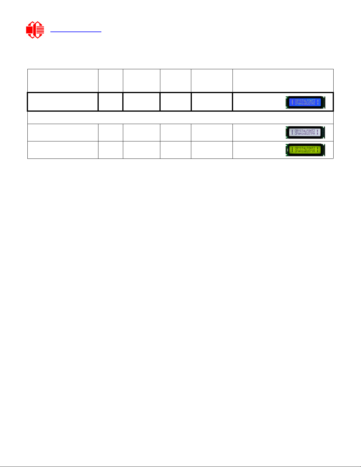
ORDERING INFORMATION
PART NUMBER FLUID
LCD
GLASS
COLOR
IMAGE POLARIZER
FILM
BACKLIGHT
COLOR/TYPE
CFAH1602O-TMI-ET STN blue negative transmissive white LED
Additional variants (same form factor, different LCD mode or backlight):
CFAH1602O-TFH-ET FSTN neutral positive transflective white LED
CFAH1602O-YYH-ET STN yellow-green positive transflective yellow-green LED
Crystalfontz America, Inc. CFAH1602O-TMI-ET Character LCD Module Data Sheet
www.crystalfontz.com Hardware v0.1 / Data Sheet v1.0
July 2010 Page 7
MECHANICAL SPECIFICATIONS
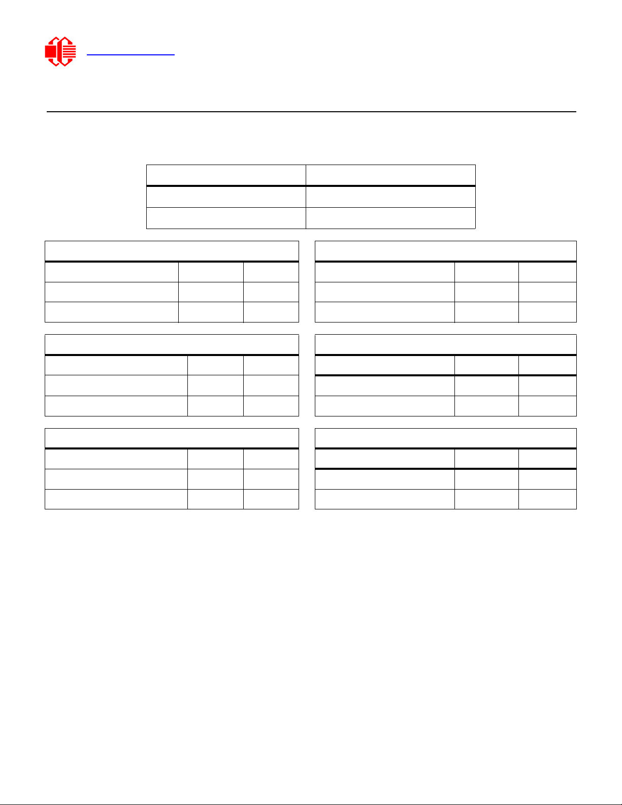
PHYSICAL CHARACTERISTICS
ITEM SIZE
Number of Characters and Lines 16 Characters x 2 Lines
Weight 32 grams (typical)
Pixel Detail (millimeters) Character Detail (millimeters)
Width Height Width Height
Pixel Size 0.55 mm 0.65 mm Character Size 2.95 mm 5.55 mm
Pixel Pitch 0.60 mm 0.70 mm Character Pitch 3.55 mm 5.95 mm
Viewing Area Active Area
Width Height Width Height
Millimeters 66.0 mm 16.0 mm Millimeters 56.2 mm 11.5 mm
Inches 2.60" 0.63" Inches 2.21" 0.45"
Module Overall Module Depth
Width Height Maximum Nominal
Millimeters 85.0 mm 25.2 mm Millimeters 13.5 mm 13.2 mm
Inches 3.35" 0.99" Inches 0.53" 0.52"

Crystalfontz America, Inc. CFAH1602O-TMI-ET Character LCD Module Data Sheet
www.crystalfontz.com Hardware v0.1 / Data Sheet v1.0
July 2010 Page 8
MODULE OUTLINE DRAWING
Figure 1. Module Outline Drawing
13
14
1
2
K
A
56.20 Active Area
66.00 Viewing Area
71.20 Bezel
80.30 PCB Adjusting Hole
85.00±0.50 Overall (PCB)
11.50 AA
16.00 VA
19.58 PCB A.H.
25.20±0.50 Overall (PCB)
1.70
4.60
6.85
13
14
1
2
K
A
3.00
7.40
10.00
14.90
8.90
13.20 Nominal
1.60
13.50 Maximum
2.90
2.72
7.40
2.50
2.80
1.50
1.70
1.70 4.98
P2.54(7-1)=
15.24
1.20
2.54
2.95
3.55
5.55
5.95
0.40
0.60
0.55
0.60
0.65
0.70
0.05
0.05
Note: Tolerance is ±0.3 mm unless specified.
4-R1.3 NO PTH
14-Ø1.0 PTH
14-Ø1.8 Pad
See Pin
Detail A
Pin Detail B
Character Detail C
Pin Detail A
Pixel Detail D
See Pin Detail B
See Character
Detail C
See Pixel
Detail D
www.crystalfontz.com/products/
Crystalfontz America, Inc.
Scale:
Units:
copyright © 2010 by
Drawing Number:
Date:
Hardware Rev.:
Sheet:
Part No.(s):
of
CFAH1602O-TMI-ET
2010/06/11
Not to scale
Millimeters
CFAH1602O_master v0.1
11

Crystalfontz America, Inc. CFAH1602O-TMI-ET Character LCD Module Data Sheet
www.crystalfontz.com Hardware v0.1 / Data Sheet v1.0
July 2010 Page 9
ELECTRICAL SPECIFICATIONS
SYSTEM BLOCK DIAGRAM
Figure 2. System Block Diagram
/27
45
49
'
&$Ä&$
%QOÄ
5GIÄ
$KCUCPF
2QYGT%KTE KV
8Q
84
-Ä-
8&&
855
5GIÄ
5GI&TKXGT
#
-
Z.%& .'&
$CEMNKIJV
*&
'S KXCNGPV

Crystalfontz America, Inc. CFAH1602O-TMI-ET Character LCD Module Data Sheet
www.crystalfontz.com Hardware v0.1 / Data Sheet v1.0
July 2010 Page 10
DRIVING METHOD
ABSOLUTE MAXIMUM RATINGS
DRIVING METHOD SPECIFICATION
Duty 1/16
Bias 1/5
ABSOLUTE MAXIMUM RATINGS
SYMBOL
MINIMUM
MAXIMUM
Operating Temperature* TOP -20°C +70°C
Storage Temperature* TST -30°C +80°C
Input Voltage VIVSS VDD
Supply Voltage for Logic VDD - VSS -0.3v +7v
Supply Voltage for LCD VDD - VO-0.3v +13v
*Note: Prolonged exposure at temperatures outside of this range may
cause permanent damage to the module.

Crystalfontz America, Inc. CFAH1602O-TMI-ET Character LCD Module Data Sheet
www.crystalfontz.com Hardware v0.1 / Data Sheet v1.0
July 2010 Page 11
DC CHARACTERISTICS (5V AND 3.3V OPERATION)
5V OPERATION
PART
DC CHARACTERISTICS
(4.5 to 5.5 volts)
TEST
CONDITION
SYMBOL
MINIMUM
TYPICAL
MAXIMUM
NOTES
Controller
and
Board
Supply Voltage for Logic VDD
- VSS
+4.5v +5.0v +5.5v
Input High Voltage VDD = 5v VIH +0.7v VDD Pins: E, RS, R/W,
DB0 - DB7
Input Low Voltage VIL VSS +0.6v
Output High Voltage VDD = 5v VOH +3.9v VDD
IOH = - 0.1 mA
Pins: DB0 - DB7
Output Low Voltage VOL +0.4v IOL = 0.1 mA
Pins: DB0 - DB7
Supply Current
VDD = 5v
without
backlight
IDD 1.0 mA 1.2 mA 1.5 mA
LCD
Glass
Supply Voltage for
Driving LCD
TA = -20ºC +5.2v
TA = +25ºC VDD
- VO
+3.7
TA = +70ºC +3.2v
This is a summary of the module’s major operating parameters. For detailed information, see APPENDIX C:
SITRONIX ST7066U CONTROLLER SPECIFICATION SHEET (Pg. 31).

Crystalfontz America, Inc. CFAH1602O-TMI-ET Character LCD Module Data Sheet
www.crystalfontz.com Hardware v0.1 / Data Sheet v1.0
July 2010 Page 12
3.3V OPERATION
PART
DC CHARACTERISTICS
(2.7 to 4.5 volts)
TEST
CONDITION
SYMBOL
MINIMUM
TYPICAL
MAXIMUM
NOTES
Controller
and
Board
Supply Voltage for Logic VDD - VSS +2.7v +3.3v +4.5v
Input High Voltage VDD = 3.3V VIH +2.3v VDD Pins: E, RS, R/W,
DB0 - DB7
Input Low Voltage VIL VSS +0.6v
Output High Voltage VDD = 3.3V VOH +2.4v IOH = - 0.1 mA
Pins: DB0 - DB7
Output Low Voltage VOL +0.4v IOL = 0.1 mA
Pins: DB0 - DB7
Supply Current without
backlight IDD 1.0 mA 1.2 mA 1.5 mA
LCD
Glass Supply Voltage for
Driving LCD
TA = -20ºC +5.2v
TA = +25ºC VDD - VO+3.7
TA = +70ºC +3.2v
This is a summary of the module’s major operating parameters. For detailed information see APPENDIX C: SITRONIX
ST7066U CONTROLLER SPECIFICATION SHEET (Pg. 31).
For more information about 3.3v operation, please see APPENDIX B: APPLICATION NOTE FOR 3.3V
OPERATION (Pg. 29).

Crystalfontz America, Inc. CFAH1602O-TMI-ET Character LCD Module Data Sheet
www.crystalfontz.com Hardware v0.1 / Data Sheet v1.0
July 2010 Page 13
DETAILS OF INTERFACE PIN FUNCTIONS
NOTE
The pinout of this module is not the same as many other character modules that have a
similar connector. Please carefully check the pinout of the module compared to your system
before applying power.
PIN SIGNAL LEVEL
DIRECTION
DESCRIPTION
1DB7 H/LI/O
Bidirectional databus connects to 4-bit or 8-bit standard host
databus.
When using 4-bit interface, leave unused DB3 to DB0 floating.
2DB6 H/LI/O
3DB5 H/LI/O
4DB4 H/LI/O
5DB3 H/LI/O
6DB2 H/LI/O
7DB1 H/LI/O
8DB0 H/LI/O
9EH,HLI
Read/write enable signal.
High: Read data is enabled by a high level.
High
Low: Write data is latched on the falling edge.
10 R/W H/L I High: Read (HostModule)
Low: Write (HostModule)
11 RS H/L I
Register selection input.
High: Data register (for read and write)
Low: Instruction code (for write)
12 VOvariable I/O Supply voltage for driving LCD is VO= +1v typical at VDD = +5v
which gives a VLCD = (VDD - VO) = +4v
13 VSS 0v Ground. Must be connected to an external ground
14 VDD
+5.0v
or
+3.3v*
Supply voltage for logic.
*Do NOT mix supply voltage and logic voltages.
For backlight connections, please refer to LED Backlight Characteristics (Pg. 19).

Crystalfontz America, Inc. CFAH1602O-TMI-ET Character LCD Module Data Sheet
www.crystalfontz.com Hardware v0.1 / Data Sheet v1.0
July 2010 Page 14
QUICK REFERENCE FOR PIN FUNCTIONS (FRONT & BACK PHOTOS)
Figure 3. Back View of Pins (Labeled)
Figure 4. Front View of Pins (Labeled)
NOTE
The pinout of this module is not the same as many other character modules that have a
similar connector. Please carefully check the pinout of the module compared to your system
before applying power.
(10) R/W
(5) DB3
(13) VSS
(7) DB1
(3) DB5
(1) DB7
(9) E
(14) VDD
(8) DB0
(6) DB2
(4) DB4
(2) DB6
(12) VO
(11) RS
(14) VDD
(8) DB0
(6) DB2
(4) DB4
(2) DB6
(10) RW
(12) VO
(13) VSS
(7) DB1
(3) DB5
(1) DB7
(9) E
(11) RS
(5) DB3

Crystalfontz America, Inc. CFAH1602O-TMI-ET Character LCD Module Data Sheet
www.crystalfontz.com Hardware v0.1 / Data Sheet v1.0
July 2010 Page 15
TYPICAL VOCONNECTIONS FOR DISPLAY CONTRAST
Adjust VOto +1v (VLCD = +4v) as an initial setting. When the module is operational, readjust VOfor optimal display
appearance.
Figure 5. Typical VOConnections with +5v Supply
We recommend allowing field adjustment of VOfor all designs. The optimal value for VOwill change with temperature,
variations in VDD, and viewing angle. VOwill also vary module-to-module and batch-to-batch due to normal
manufacturing variations.
Ideally, adjustments to VOshould be available to the end user so each user can adjust the display to the optimal contrast
for their required viewing conditions. At a minimum, your design should allow VOto be adjusted as part of your product’s
final test.
Although a potentiometer is shown as a typical connection, VOcan be driven by your microcontroller, either by using a
DAC or a filtered PWM. Displays that require VOto be negative may need a level-shifting circuit. Please do not hesitate
to contact Crystalfontz application support for design assistance on your application.
ESD (ELECTRO-STATIC DISCHARGE) SPECIFICATIONS
The circuitry is industry standard CMOS logic and susceptible to ESD damage. Please use industry standard antistatic
precautions as you would for any other static sensitive devices such as expansion cards, motherboards, or integrated
circuits. Ground your body, work surfaces, and equipment.
VDD
VO
VR
10 k
VLCD
GND (Ground) GND
Crystalfontz America, Inc. CFAH1602O-TMI-ET Character LCD Module Data Sheet
www.crystalfontz.com Hardware v0.1 / Data Sheet v1.0
July 2010 Page 16
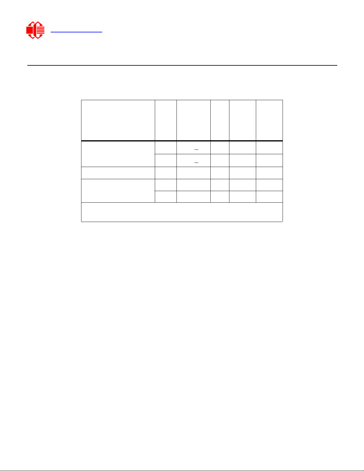
OPTICAL SPECIFICATIONS
OPTICAL CHARACTERISTICS
OPTICAL DEFINITIONS
Operating Voltage (VLCD): VOP
Viewing Angle
Vertical (V): 0°
Horizontal (H): 0°
Frame Frequency: 64 Hz
Driving Waveform: 1/16 Duty, 1/5 Bias
Ambient Temperature (Ta): 25°C
ITEM
SYMBOL
CONDITION
MINIMUM
TYPICAL
MAXIMUM
Viewing Angle (6 o’clock)
(Vertical, Horizontal)
(V)CR>2 20° 40°
(H)CR>2 -30° 30°
Contrast Ratio CR 3
LCD Response Time* T rise Ta = 25°C 150 ms 200 ms
T fall Ta = 25°C 150 ms 200 ms
*Response Time: The amount of time it takes a liquid crystal cell to go from
active to inactive or back again.
Crystalfontz America, Inc. CFAH1602O-TMI-ET Character LCD Module Data Sheet
www.crystalfontz.com Hardware v0.1 / Data Sheet v1.0
July 2010 Page 17
Definition of Operation Voltage (Vop)
Figure 6. Definition of Operation Voltage (VOP) (Negative)
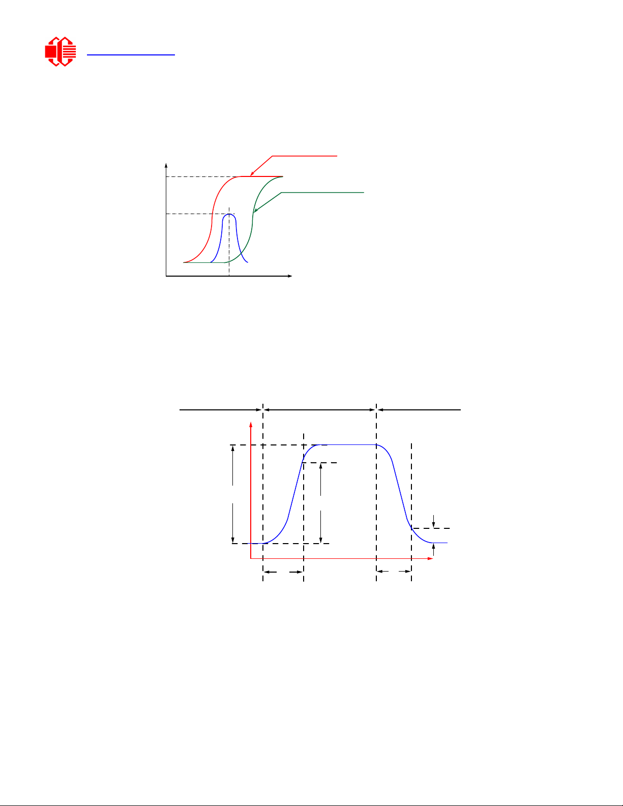
Definition of Response Time (Tr, Tf)
Figure 7. Definition of Response Time (Tr, Tf) (Negative)
Driving Voltage (V)
Intensity
CR
Maximum
100%
Vop
Selected Wave
Non-selected Wave
CR = Lon / Loff
Lon = Luminance of ON segments
Loff = Luminance of OFF segments
Unselected
State
Unselected
State
Intensity
90%
100%
Tr Tf
Selected
State
Tr = Rise Time
Tf = Fall Time
Light
Transmitted
Light
Blocked
10%

Crystalfontz America, Inc. CFAH1602O-TMI-ET Character LCD Module Data Sheet
www.crystalfontz.com Hardware v0.1 / Data Sheet v1.0
July 2010 Page 18
Definition of Vertical and Horizontal Viewing Angles (CR>2)
Figure 8. Definition of Horizontal and Vertical Viewing Angles (CR>2)
Definition of 6 O’Clock and 12:00 O’Clock Viewing Angles
This module has a 6:00 o’clock viewing angle. A 6:00 o’clock viewing angle is a bottom viewing angle like what you would
see when you look at a cell phone or calculator. A 12:00 o’clock viewing angle is a top viewing angle like what you would
see when you look at the gauges in a golf cart or airplane.
Figure 9. Definition of 6:00 O’Clock and 12:00 O’Clock Viewing Angles
Vertical
Horizontal
Eyes look up
6:00 O’clock
Bottom Viewing Angle
12:00 O’clock
Top Viewing Angle
Eyes look down

Crystalfontz America, Inc. CFAH1602O-TMI-ET Character LCD Module Data Sheet
www.crystalfontz.com Hardware v0.1 / Data Sheet v1.0
July 2010 Page 19
LED BACKLIGHT CHARACTERISTICS
The CFAH1602O-TMI-ET uses an LED backlight. LED backlights are easy to use, but they are also easily damaged by
abuse.
LEDs are “current” devices. The important aspect of driving an LED is the current flowing through it, not the voltage
across it. Ideally, a current source would be used to drive the LEDs. In practice, a simple current limiting resistor in line
from a voltage source will work well in most applications and is much less complex than a current source.
Choose one of these two methods to power the backlight:
(1) Connect power directly to A and K.
(2) Power backlight by using RLIMIT in J1.
The two methods are described below.
How to Power LED Backlight Directly Through A and K
Using this method, the backlight may be dimmed by PWM (Pulse Width Modulation). The typical range for the PWM
frequency is from 100 to 300 Hz.
Figure 10. Direct A and K Backlight Connections Enables PWM Dimming
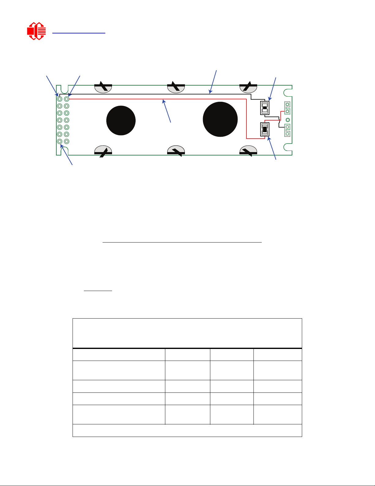
How to Power LED Backlight Using RLIMIT in J1
Supply power to backlight by connecting RA to VDD (pin 13, supply voltage for logic) and J1 to GND (pin 14, ground).
NOTE
Do not connect +5v directly to the backlight terminals. This will ruin the backlight.
NOTE
The module is shipped with a size 0805 0Ωresistor loaded at RA. We recommend that you
remove this resistor.
LED
Backlight
IRLML2502
(typical)
GND
RLIMIT
+5v
1K :
PWM signal
from
microcontroller
ILED
VLED
A(LED+)
K(LED-)
Crystalfontz America, Inc. CFAH1602O-TMI-ET Character LCD Module Data Sheet
www.crystalfontz.com Hardware v0.1 / Data Sheet v1.0
July 2010 Page 20
Figure 11. Use RLIMIT in J1 for LED Backlight Connection "Always On"
You need to know what the forward voltage of the LEDs is so you can calculate the current limiting resistor (RLIMIT). The
forward voltage will vary slightly from display to display.
The equation to calculate RLIMIT is:
RLIMIT (minimum) =
The specific RLIMIT calculation for the CFAH1602O-TMI-ET at VDD = +5v is:
RLIMIT = = 94Ω(minimum)
Backlight Characteristics
Test Conditions: 25°C, 50-60% Relative Humidity
Light dots on blue background.
PARAMETER MINIMUM TYPICAL MAXIMUM
Forward Current (ILED)
v = +3.5v 14.4 mA 16 mA 20 mA*
Forward Voltage (VLED) +3.4v +3.5v +3.6v
Reverse Voltage (VR) +5.0v
Luminous Intensity** (IV)
ILED = 16 mA 264 cd/m2330 cd/m2
*Driving the backlight above 20 mA will shorten its lifetime.
RA
K
A
V
DD
(Pin 14)
J1
Add 0805 resistor at J1.
If you are concerned about power dissipation, exchange the 0
resistor for a
resistor value to compliment the resistor value loaded at J1.
GND (Pin 13)
0
0
DB7 (Pin 1)
Pin order is not typical.
J1 goes to Pin 13, GND
RA goes to Pin 14, V
DD
(LED+)
(LED-)
VDD (Supply Voltage) - VLED (Typical LED Forward Voltage)
ILED (Typical LED Forward Current)
0.016 A
5v - 3.5v
This manual suits for next models
2
Table of contents
Other Crystalfontz America Control Unit manuals

Popular Control Unit manuals by other brands


Cobra USA
Cobra USA Fi2000 quick start guide

Becker
Becker CentralControl CC41 Commissioning Instruction

Elo TouchSystems
Elo TouchSystems DMS-SA19P-EXTME Quick installation guide

EOS
EOS EmoTouch 3 operating instructions

SMC Corporation
SMC Corporation IL211 Series instruction manual

Trox Technik
Trox Technik XS installation manual