MINI-EMITTER F.M
FM-1
TECHNICAL CHARACTERISTICS
Voltage...................................................... 12 VDC. (from 9 to 15)
Consumption.............................................. 50 mA.
Operating Frequenc .................................. From 85 to 110 Mhz.
Protection Against Polarit Inversions........ Yes.
Sizes........................................................... 69 x 39 x 20 mm.
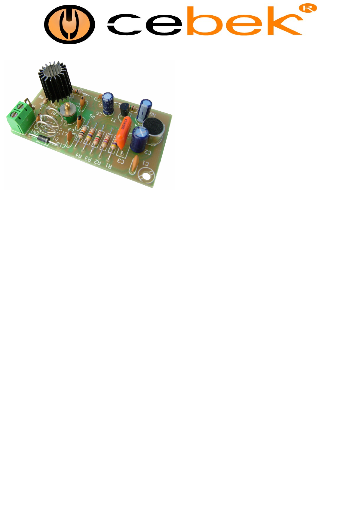
The FM-1 module is an mini-emitter, speciall designed to start in the Radio amateur field. You could emit in the
commercial band from 88 up to 108 MHz. and receive through an radio with F.M band. It includes microphone.
The module is supplied from 9 up to 15 VDC. We recommend ou our FE-2 power suppl or a 12 VDC
OPERATING
POWER SUPPLY OF THE MODULE : The FM-1 circuit have to be supplied b a 12 VDC power suppl
correctl filtered. Do not use suppliers or rectifiers disturbing the module's operating. Then, we recommended
ou the FE-2 power suppl which has been developed to perfectl answer to the circuit needs or a 12 VDC
Batter for mobile applications.
Install a fuse and a switch as it is indicated in the drawing. Both are necessar and obligator to assure a
correct module's protection as well as for our own safet as it is indicated in the "CE" regulation.
Connect the positive and the negative of the power suppl to the corresponding input indicated in the wiring
map. Use cable as short as possible. Verif that assembl has been correctl done.
ANTENNA CONNECTION : As antenna for our FM-1 module, ou could use an metallic rod with a length of
72cm. The distance between module and antenna had to be as short as possible and tr to install antenna
directl to the module output. If ou have to use cable for this connection, the cable had to be shielded and
inferior than 20 cm. Do not connect mod le to the power s pply if the antenna is not connected to avoid
to damage o tp t transistors.
The positive cable of the antenna does not touch the enclosure where the module will be installed.
INSTALATION : To obtain a correct operating of the module, it has to be installed in a metallic box and the
ground has to be connected.
OPERATING : To adjust the emitter, use a commercial radio with FM. Place it at 3 m awa from the FM-1
module and adjust the reception between 100 and 104 Mhz.
Verif that the antenna is connected to the module and then suppl the module. Using a plastic screw- driver
adjust the emission frequenc thanks to the trimer. When ou listen to a noise from the receiver ou have to
adjust the receiver frequenc up to obtain the sound emitted thanks the microphone.
www.cebek.com - sat@cebek.com


