DIGIWAY PTY P750 User manual
DIGIWAY PTY LTD
1
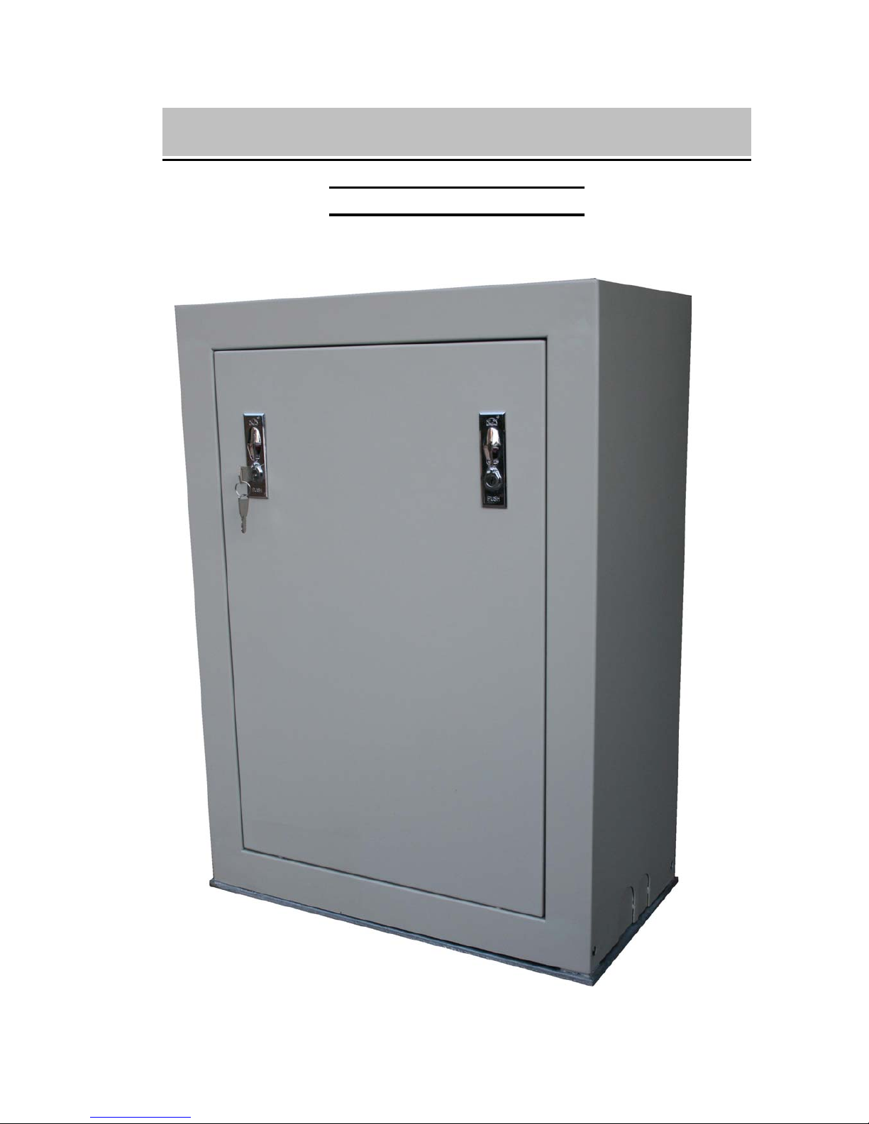
P750 Sliding Gate Motor
P550 Sliding Gate Motor
Version -V2.X
INSTRUCTION MANUAL

DIGIWAY PTY LTD
2
ATTENTION To prevent electrical shock, disconnect from power source before installing or service
ATTENTION Electricity and power motors associated accessories could be fatal or at least cause
seriously injury. All main voltage wiring must be installed by a licensed electrician.
ATTENTION Additional safety device MUST be fitted such as Photo Electric Beam, Loop Detectors.
ATTENTION Before do the manual release, the mains power switch must be off even there is no
power.
ATTENTION Before power on, the manual release MUST engaged
ATTENTION Gate opened stopper and closed gate stopper MUST be installed.
P550 Sliding Gate Motor
IMPORTANT SAFETY WARNING
DIGIWAY PTY LTD
3
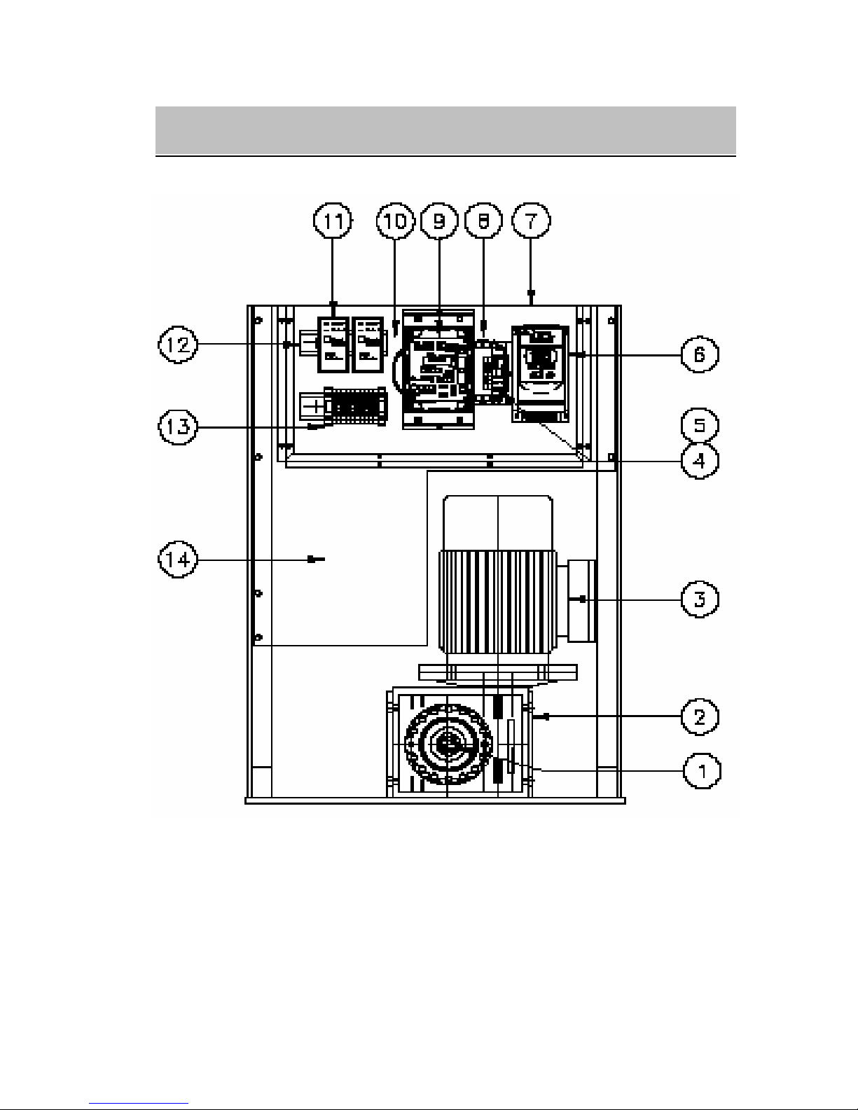
Fig -1
1) Manual Release bolts 2) Gear box
3) Motor 4) Circuit breaker
5) Terminals 6) Inverter
7) Perspex 8) EMC filter
8) Main control board 10) Transformer
11 Loop detector (option) 12 Din rail
13) Access control terminals 14) Room for other accessary
GENERAL LAYOUT
DIGIWAY PTY LTD
4
1. General Descriptions
The P550 and P750 sliding gate motors was designed for heavy duty industry track gate or cantilever
gate. Heavy duty three phase industry motor driven by VSD (variable speed drive), gate can run at
different speeds. Built in encoder and intelligent controller combination can make the gate running
more smoothly. The controller can receive the signals from swipe card, loop detectors, remote control,
photo-electric beams and any kind of access control system. Galvanised metal sheet and powder coated
high quality cabinet(1.5mm thickness) has remove door (P750) and plenty of room for the access
control accessaries including din rail mounting. 50VA transformer (12V/24v/2A) can directly drive
magnetic lock, warning lights etc.
2. Technical Specifications
Power supply 230/240V AC at 10A
Output voltage 230V AC three phase (via) inverter, Max. 0.75KW
Motor rate Three phase two poles 0.55KW (P550) or 0.75KW (P750)
Gate type Track or cantilever
Drive speed Up to 700mm/sec (with big opinion)
Max. gate length No limitation
Fully programmable Auto close time, PE trig close time etc.
Accessories power supply 12V@2A or 24@2A, Max. 50VA, protected by 1A fuse
3. Control Board layout
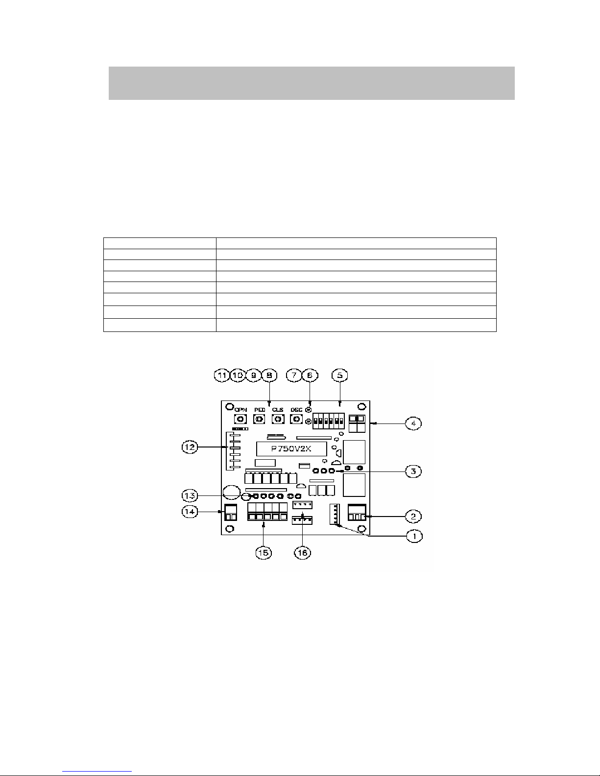
Fig-2
1) Plug to the inverter 2) Lock relay output
3) Drive signal LED 4) Gate closed relay output
5) DIP switch 6) Gate status display LED-Green
7) Gate status display LED-Red 8) OSC open/stop/close button
9) CLS close button 10) PED pedestrian button
11) OPN open button 12) 6 pins remote plug
13) Control signal display LED 14) Input interface power 12V AC
15) Control signal plug 16) Encoder plug
CONTROL INPUIT AND BUTTON

DIGIWAY PTY LTD
5
Open (OPN) input & OPN push button
The OPN inputs are Push Button OPN and Terminal OPN input. Push OPN button or Activating
(connect OPN terminal to the COM (+12V)) the OPN input will start the gate to open. When gate
opened, if OPN is still activating, the gate will stay open.
Pedestrian Access (PED) input and Pedestrian (PED) push button
The pedestrian input partly opens gate.
CLS push button
The CLS push button on control board is to close gate.
OSC (open/stop/close) input and OSC push button
OSC input and OSC push button is for manual operation. Push to open the gate, push again stop gate,
another push close the gate. When gate stopped by OSC input, auto close mode does not apply.
Photoelectric safety beam (PE) input
If the P.E input activated while gate is closing, the gate will stop or reopen depending on the DIP
setting. If the gate in the opened position and P.E beam activated, the gate will stay in opened.
Encoder inputs
Encoder in mounted on the motor shaft. There is not service is required. 4 pins socket from encoder
directly plug in on the control board. Two plugs on the control board are for right hand or left hand gate.
Drive signals (between control board and inverter)
Plug 1 link inverter and control board. This is five pins plug. Two pins for 12VDC supply from inverter
to control board and other three pins is from control board to inverter, open, close and running
frequency signals.
Lock output signal
Lock output relay has COM, N/C, N/O outputs. The output can be pause or presence set by DIP3.
Gate close (status) output signal
When gate in closed position the relay contact is on, this used to send closing signals to alarm system.
As long as the gate is not closed, the relay contact will be off and tell the alarm system, the gate is open.
4. DIP SWICTH FUNCTION
SET/RUN (DIP1) ON=SET, OFF=RUN
Dip1 ON selects setting mode.
Slave/Master (DIP2) ON=SLAVE OFF= MASTER
This is for two motors (reserved for late use)
LOCK Output (DIP3) ON= PLUSE OFF= PRESENCE
DIP3 ON selects lock output is pulse at every start cycle. DIP3 OFF selects lock output is presence.
The lock relay will be on if the gate is in opening and closing cycle. All other situations will be off.
Security close (DIP4) ON=SEC CLS OFF=NO SEC CLS
DIP4 ON selects security close mode. In this mode, while the gate is opening, if the PE beams trigged
and clear, the gate stops and begins to close; even it is not fully open. While the gate is closing, if the
PE trigged, the gate will stop (not reopen) until the PE beams is clear, then gate continues to close.
DIP4 OFF no this function. DIP4 is prior to DIP5
PE trig close (DIP5) ON=PE CLS OFF=NO PE CLSDIP5 ON selects PE
beam trig auto close mode. In this mode, if P.E beams trigged and clear the gate will auto close after
gate opened. If the P.E beams trig again, the gate will reopen as long as the P.E input active,
CONTROL INPUIT AND BUTTON

DIGIWAY PTY LTD
6
until gate is fully opened. If the PE is clear, the gate will open another 2 seconds, then gate will close
again after PE close delay time. DIP5 OFF no this function. DIP5 is prior to DIP6.
Auto CLS (DIP6) ON=AUTO CLS OFF=NO AUTO CLS
DIP6 ON selects Auto close mode. I this mode, the gate will auto close after standard auto closed time.
If DIP6 OFF, no this function.
5. Timer Settings
Push Buttons functions
Button Dip1 on---STD Setting SPE Setting Dip1 off---Running
OPN Open Length Set Sync delay time Full open
PED Auto close time set Motor stop time set Pedestrian open
CLS Manual close gate PE close time set Close
OSC Lock pulse time set Reserved OSC
5.1 STD(standard) time setting mode
To get into standard setting mode, just set DIP1 to on. Following settings can be set in standard setting
model
Gate length set up -- Limit switch set up
a) Connect 240V AC (if not done) and make sure power is off.
b) Releases clutch and push gate to middle position, and then engage the clutch.
c) Make sure no signals connect to OPN, PED, OSC and PEB terminals. Set DIP6 on.
d) Turn power on, gate should start close at low speed. If not, turn power off, change motor direction
by swapping any two of three phases (from motor side)
e) Power on again. Gate should start to close. Look at RED LED should be flash and GREEN LED
is off. If not, turn power off, change encode plug to other connector.
f) Power on again, gate start close, RED LED is flash and GREEN LED is off. When gate hit the
closed stopper, gate will stop. For P550 the gate will open a little bit, do not move the gate, just
go to next step.
g) Set DIP1 on. Push and hold OPN button, gate will start open at low speed. When gate reach
opened position, (about 50mm away opened stopper). Just simply release the OPN button.
Controller will save the current position as fully opened position. While hold OPN button, push
and release PED button will save current gate position as PED opened position.
h) Set DIP1 off and push CLS button, gate will start to close. When gate fully closed, gate will be
ready to operate. Then try to open and close. If not satisfied with the position, just repeat step (g)
to (h).
Auto close time set
Push and hold on PED for the auto close time setting. Now the red and green LED flash fast
alternatively, When reached the required time simply release PED button. Set DIP1 OFF. The gate
controller will back to working mode.
Lock pulse time set
Push and hold on OSC for the lock pulse time setting. Now the red and green LED flash fast
alternatively, and when gate reached the required time, simply release OSC button. Set DIP1 OFF.
The gate controller will back to working mode.
5.2 SPE(special) time setting mode
To get into special setting mode, turn power off, set DIP1 on. Push and hold CLS button then turn
power on, LED will be on for short time, after LED off simply release CLS button. Gate controller is
getting into special time setting mode.
CONTROL BOARD SETTING

DIGIWAY PTY LTD
7
Sync delay time (Motor2 delay time, reserved late use)
After controller get into special time setting mode, Push and hold on OPN for the sync delay time
setting. Now the red and green LED flash fast alternatively, when reached required time, simply
release OPN button. If no other time need set, simply set DIP1 off, the gate controller will back to
working mode.
Motor Stop time
Push and hold on PED for the motor stop time setting. Now the red and green LED flash fast
alternatively and when gate reached required time, simply release PED button.
PE trig close time
Push and hold on CLS for the PE trig close time setting. Now the red and green LED flash fast
alternatively and when gate reached required time, simply release CLS button.
Reserved
Push and hold OSC reserved late use.
Factory default setting
Timer F/Setting Step Setting Method Range
Full Open Length 10M 0.7mm STD& OPN Button No limitation
PED Open Length 5M 0.7mm STD& OPN+PED Button No limitation
Auto Close Time 30sec. 0.1sec. STD& PED Button 0-6550sec.
Lock Pulse Time 0.8ec. 0.1sec. STD& OSC Button 0-25sec.
Motor Stop Time 1.0sec. 0.1sec. SPE& OPN Button 0-25sec.
Sync Delay Time 0.5sec. 0.1sec. SPE& PED Button 0-25sec.
PE Auto close Time 2sec 0.1sec SPE& CLS Button 0-25sec
Reserved 0 0 SPE& OSC Button 0
To restore factory setting, turn power off and set DIP1 on, push and hold CLS button then power
on. While hold CLS button, set DIP1 off, release the CLS button. Now controller restored factory
setting from memory.
Attention: First time power up, the motor will run at low speed in close direction
(if DIP6 is on) and hit receiving post. Next open command gate will open at low
speed until to fully opened. The controller will calculate the gate length and
compare it with original gate length. If it is right, the gate will back to normal
operation, otherwise, gate will run at low speed.
6. Inverter settings
When the gate stops, the inverter’s display is opening high-speed frequency and flash. This frequency
can be changed by up and down arrows on the inverter. The following form is the inverter’s standard
setting for the automatic gate application. Not mentioned function keep as factory setting.
Function F Function Description Setting Unit Note
Acceleration time 1 Acceleration time 2.0 Sec.
Deceleration time 2 Deceleration time 2.0 Sec.
Freq. Upper limit 6 Max. Frequency 60 Hz
Freq. Lower limit 7 Min. Frequency 0 Hz
SP1 Frequency 8 Gate Close High Speed 35 Hz
Start/Stop/Control 10 Terminals 1
Multifunction Input 20 Reset Terminal Function 6
SP2 Frequency 26 Gate Open Low Speed 20 Hz
SP3 Frequency 27 Gate Close Low Speed 15 Hz
CONTROL BOARD SETTING

DIGIWAY PTY LTD
8
7. Wiring diagram
Fig-3
WIRING DIAGRAM

DIGIWAY PTY LTD
9
8. Manual release
P550 and P750 have different manual release mechanisms please read the
instructions carefully.
8.1 P550 manual release
A: What to do during a power failure:
The gate can be manually pushed open and close if there is no power. To do this, you need to release
the release bolt.
(1) Switch off the power switch at the mains supply.
(2) Open the front flap and insert the spanner (provided) into the hole. The spanner should fit onto
the bolt nicely.
(3) Rotate the spanner anti-clockwise several times (6-8 turns) until light resistance is felt. Do
not force.
(4) The gate can now be manually opened and closed.
B: What to do if power is reconnected:
At this stage, the gate should be able to be pushed open and close manually (using hands). If not, read
and carry out instructions in ‘What to do during a power failure’ first, before carrying out these
instructions.
(1) Make sure the switch at the power point is still switched OFF.
(2) Open the front flap and insert the spanner (provided) into the hole. The spanner should fit onto
the bolt nicely.
(3) Rotate the spanner clockwise until light resistance is felt. Do not force.
(4) (a) Manually push or pull the gate until a clicking noise is heard or if it cannot be pushed any
further.
(b) If no click is heard AND the gate is still able to be pushed fully open, turn the spanner
clockwise a little more (half a turn – Do not use force) and try this step 4(a) again.
(5) If needed, rotate the spanner clockwise again until finger-tightness is felt. Do not force.
(6) Turn on the power at the power point. , the gate should start to close if no signal input on PEB
(safety) and OPN (open) inputs. When gate hit on receiving post, the controller will recall the
all the settings and ready to operate.
MANUAL RELEASE
MANUAL RELEASE

DIGIWAY PTY LTD
10
8.2 P750 manual release
A: What to do during a power failure:
The gate can be manually pushed open and close if there is no power. To do this, you need to release
the release bolt.
(1) Open the front door and turn the switch(circuit breaker) OFF(even though there is no power)
(2) Fit spanner (provided) onto the manual release bolt nicely.
(3) Turn the spanner anti-clockwise 1 turn. Take the spanner off the manual release bolts. The
gate can now be manually opened and closed.
(4) After the gate was pushed to the required position, fit the spanner onto the manual release
blots, clockwise turn and make the bolts tight, otherwise maybe cause oil leaking.
B: What to do if power is reconnected:
(1) Make sure the switch (circuit breaker) is still OFF.
(2) Fit the spanner onto the bolt nicely and clockwise turn the manual release blots and make sure
the bolts is tight
(3) Turn on the switch on, the gate should start to close if no signal input on PEB (safety) and
OPN (open) inputs
(4) When gate hit on receiving post, the controller will recall the all the settings and ready to
operate.
TROUBLE SHOOTING GUIDE

DIGIWAY PTY LTD
11
9. Trouble Shooting Guide
9.1 Display information on main control board – see Fig-2
(1) Gate status LED
Gate Status(Position) \ LEDs Status LED-Green (6) Status LED-Red (7)
Gate in closed position Slow Flash on
Gate is opening Fast flash off
Gate in opened position on Slow flash
Gate is closing off Fast flash
Gate stop in the middle Alternatively flash Alternatively flash
Gate stop in the middle: which means the gate stop by OSC input and at this position the auto close
does not apply. If the gate hit something or mechanical jammed, gate will stop and green and red status
LEDs alternatively flash.
(2) Input LEDs
Inputs LEDs\ Input status Input Active Input inactive
Open input –OPN LED on off
Pedestrian input – PED LED on off
Open/Stop/Close – OSC LED on off
Photo Electric Beam- PEB LED on off
Encoder input -A On or off On or off
Encoder input -B On or off On or off
(3) Drive Signal LEDs
Drive Signal LEDs\ Output status Input Active Input inactive Gate Status
Gate opening- Green LED on off Gate opening
Gate closing – Red LED on off Gate Closing
Low speed – Yellow LED on off Low speed
9.2 Trouble Shooting Guide
Malfunction Possible causes Countermeasure
Gate not open 1) No power
2) Already in opened position
1) Check the power
2) First time power up, for safety reason, the
controller treated current position as opened
position.
Gate not close 1) Safety input PEB active
2) OPN input active
1) Check the safety device, N/O contact
required.
2) Check access control system
Gate run little bit
then stop and
Status LEDs flash
1) No encoder input
2) mechanical jammed
1) Aux. power supply fuse
2) power off and disengage the motor and
push and pull the gate manually
Gate opened or
closed position not
right
1) mechanical release bolts not
tight (P750 only)
1) Power off and tight the bolts(P750 only)
and power again. Please follow the manual
release procedure.
CONDITION OF SALE
Other manuals for P750
1
This manual suits for next models
1
Table of contents
Other DIGIWAY PTY Garage Door Opener manuals


Popular Garage Door Opener manuals by other brands

Chamberlain
Chamberlain HD920EV owner's manual

Chamberlain
Chamberlain ELITE Series user guide

Linear
Linear H-S Installation and owner's manual

B&D
B&D Roll-A-Door 2 Series installation instructions

Beninca
Beninca Aurora Super Operating instructions and spare parts catalogue

CAME
CAME V6000P installation manual

Chamberlain
Chamberlain merlin MT600 Installation and operating instructions

Craftsman
Craftsman 53479 owner's manual

Beninca
Beninca PONY manual

Chamberlain
Chamberlain Whisper Drive Security+ HD600 owner's manual

BFT
BFT BOTTICELLI SMART BT A 850 Installation and user manual

Chamberlain
Chamberlain 041D1739-1 instructions


