Dillenger CONVERSION KIT User manual

CONVERSION KIT
Please read through carefully before beginning your conversion
User Manual
Dillenger Premium O Road Kit -
Samsung Powered
English

2
SAFETY
PLEASE NOTE
Mechanical Safety Check:
Routinely check the condition of your bike. Make sure no fasteners have come loose. Perform
a visual inspection of the whole bicycle before every ride. Make sure tyres are correctly inated
within the range given on the tyre sidewall. Check your brakes for proper operation.
Your First Ride:
Be sure to pick an area away from cars, other cyclists, obstacles or other hazards to become
familiar with the controls, features and performance of your new electric bike.
We highly recommend the purchase of the Dillenger hub motor
conversion kit. It will make your installation and ongoing maintenance
much easier. This can be purchased online.
Thank you for purchasing your new Dillenger conversion kit! We know you’ll love it, and with
some care it should last for a very long time. Please read through this manual carefully before
operating the kit.
THANK YOU

3
Contents
Thank You 2
Safety 2
Item Check List 4
Install Overview 5
Installation Process 6
Installation instructions 7
Cassette and Disk Brake Install 7
Wheel Install 8
Battery Cradle Install 10
Battery Install 11
Handlebar Controls Install 11
Display Install 12
Thumb Throttle Install 13
E-Brake Sensors Install 14
Removable Pedal Assist Sensor (RPAS) Install 15
Wiring Install 16
Tidy Up 17
Battery Operation 18
Turning Your Bike On/O 18
Charging 19
Maintenance and Care 20
Trouble Shooting 21
Specications 25
Contact Us 27

4
ITEM CHECK LIST
Each conversion kit is tested for quality control before shipping to a customer. Before
converting your bike, it’s a good idea to lay each of the components out to visiualise how they
will come together on your bicycle.
●Before you begin your conversion, it can be helpful to lay everything out rst and make sure
all the parts are there.
●Something missing? Double check the box, even under the aps. Those small parts can be
sneaky. If you still can’t nd it let us know and we’ll assist you ASAP.
In the box you’ll nd:
- Motor wheel
- Battery with keys and cradle
- PAS, throttle, and e-brake sensors
- LCD display
- Wiring
- Fasteners

5
INSTALL OVERVIEW
Remove Contents
Take your components out of the box. Remove the
protective packaging. Keep track of all the parts that you
remove from the box. Remove the battery and put it on
charge.
1.
Installation
Once you have your bike ready for installation, the rst
step (after transferring your rim tape, tube and tyre) is
to install the wheel and secure the axle nuts. Take note
of the order or the washers so that you can replicate
this when installing into the frame. Then move on to the
battery cradle/ controller and handlebar controls.
3.
Ride!
Once the battery is fully charged, you’ve checked your
tyre pressures and fasteners you’re now ready to go!
5.
Prepare you bike
Make sure you have measured your dropout slot
widths (approx. 10mm) and the clearance between your
dropouts (approx. 135-140mm for the rear of the frame).
Remove your current wheel, remove the tyre, tube, rim
tape and also your handlebar grips, shifters and brakes.
2.
Tidy Up
After you have installed all of the components needed to
control each part of the kit, it’s now time to tidy up the
wiring harness and make your conversion look nice and
neat.
4.

6
INSTALLATION PROCESS
Before beginning your conversion, there are
a couple things you can do that will make
the installation more ecient. Remove your
handlebar controls such as your brakes,
shifters and grips. Remove your rear wheel
and install your existing tube, tyre and rim tape
(recommended) onto the new electric wheel.
The rst step in any conversion is installing the
wheel. The easiest way to take o your wheel
is to turn your bike upside down so that your
bike rests on the handlebars, and the seat.
Your seat height may need to be adjusted to
ensure the bike will be stable, when upside
down.
Take o your disk brake caliper from the
frame, or release your V-brakes if you have not
done so already. For disk brake users, it’s much
easier to t the motor wheel with the caliper
removed.
If your bike has gears, it can also be helpful to
remove the derailleur before installation of the
rear wheel.
Pre Installation Tips
The installation instructions for this kit are show in this video:
https://www.youtube.com/watch?v=Arg5zSV3Cl8
Once you’ve taken your old wheel out of your bike and put the tube and tyre on the new
motor wheel, you can install the gear cluster on the motor.
Unlike our previous rear wheel hub motors, this motor uses a splined cassette. You can use
your current cassette (up to a 9 speed), or get a new cassette for the wheel.
For those with disk brakes, the disk brake rotor installs onto the side of the motor hub just
like a regular hub.
Tighten the bolts to maximum 5Nm (40 lbs) tightening torque. If you overtightened these
bolts, you may risk stripping the hub which is not covered by warranty. Make sure that the
bolts aren’t too long, otherwise they’ll interfere with the internal parts of the motor.
If you don’t have disk brakes, you can leave this side of the hub untouched.
In this manual we will describe the main steps in the installation process, but we strongly
recommend use the video as well. Seeing the steps in the video will help you to understand
each step and make the process a lot easier.

7
INSTALLATION INSTRUCTIONS
The installation instructions for this kit are show in this video:
https://www.youtube.com/watch?v=Arg5zSV3Cl8
Cassette and Disk Brake Install
Once you’ve taken your old wheel out of your bike and put the tube and tyre on the new
motor wheel, you can install the gear cluster on the motor.
Unlike our previous rear wheel hub motors, this motor uses a splined cassette. You can use
your current cassette (up to a 9 speed), or get a new cassette for the wheel.
For those with disk brakes, the disk brake rotor installs onto the side of the motor hub just
like a regular hub.
Tighten the bolts to maximum 5Nm (40 lbs) tightening torque. If you overtightened these
bolts, you may risk stripping the hub which is not covered by warranty. Make sure that the
bolts aren’t too long, otherwise they’ll interfere with the internal parts of the motor.
If you don’t have disk brakes, you can leave this side of the hub untouched.
In this manual we will describe the main steps in the installation process, but we strongly
recommend use the video as well. Seeing the steps in the video will help you to understand
each step and make the process a lot easier.

With your bike upside down, your wheel should be pushed all the way down into the
dropouts to make sure it’s a nice and tight t. This is very important. If the dropouts are
not embedded rmly in the bottom of the drop out slots this could cause failure of the
dropouts or cause the electric hub axle to become unsecured.
Tighten to approx. 30-40Nm (250 - 350 in lbs). If you would like to install the torque arm on
the rear wheel, please see the manual for the Arc torque arm on the website.
Your rear derailleur and disk brake callipers can now by reinstalled if they were removed
prior to the installation of the rear wheel.
8
Wheel Install
Once you have installed the disk brake, loosen the axle nuts on the electric wheel. This
will allow the axle to slot into your dropouts. We are showing the most common way
that the fasteners/ washers can be arranged, but it is possible you will discover a more
suitable way to arrange them, depending on your bike and gear set layout. If you need
to space the rear dropouts further, you can use the washers and spacers provided. If the
you need more room on the gear set side, space the hub over with the washers provided,
or if you need to space the hub evenly over to the disk brake side, you can rearrange the
fasteners to achieve this.
The distance between your dropouts should be around approx. 135-140mm. Your rear
dropouts/chain stays will ex in and out a certain amount without causing any structural
issues. The dropout axle slots should be approx. 10mm however you may need to le o
a thin layer of paint for the axle to slot in all the way. The axles are designed to be a very
tight t, so don’t stress if you need to remove a small amount of material, this is normal.
So long as the hub is orientated so that the freewheel thread side is on the chainwheel
side of the bike, it will rotate in the correct direction.

With your bike upside down, your wheel should be pushed all the way down into the
dropouts to make sure it’s a nice and tight t. This is very important. If the dropouts are
not embedded rmly in the bottom of the drop out slots this could cause failure of the
dropouts or cause the electric hub axle to become unsecured.
Tighten to approx. 30-40Nm (250 - 350 in lbs). If you would like to install the torque arm on
the rear wheel, please see the manual for the Arc torque arm on the website.
Your rear derailleur and disk brake callipers can now by reinstalled if they were removed
prior to the installation of the rear wheel.
9
Wheel Install Continued

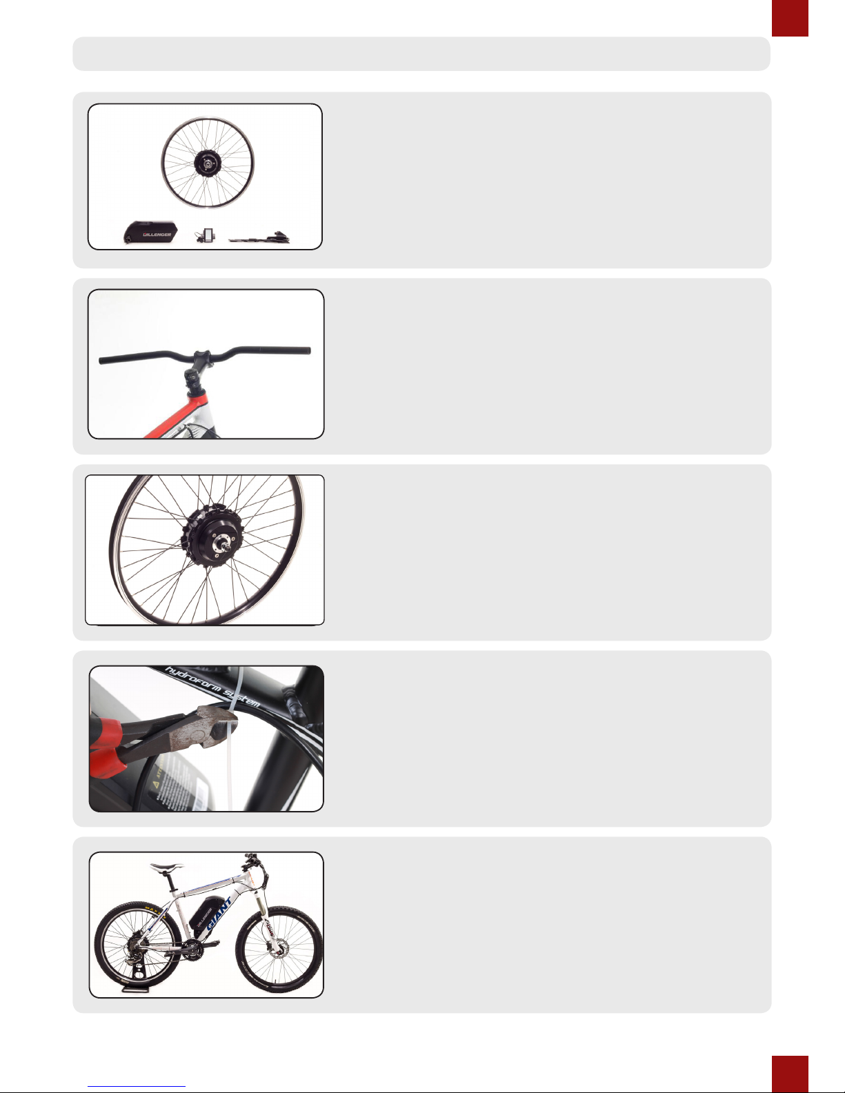
The battery installation starts with mounting the battery cradle. This is what your battery
will attach to and it’s also where the controller is housed.
The most common way to install the battery is by using the drink bottle holder mounts on
your frame. Simply remove your drink bottle holder, (if you have one) and you’re ready to
install the battery cradle.
You will be able to tell where your cradle will t best by simply holding the cradle up against
your frame. You will have a few dierent height options however keep in mind you need
room above the cradle to manoeuvre the battery in and out. You can secure the cradle by
using your existing bolts/screws and tightening them up.
Be careful not to over tighten your bolts/screws as drink bottle mounts and threads are
only ‘nutserts’. If installed correctly the battery and cradle should feel very secure and not
bounce over bumps.
If drink bottle mounts aren’t an option, there are plenty of battery attachment options
other than the method above, such as:
1. Install the battery on a rear rack (contact Dillenger for this option).
2. Use large hose clamps or heavy-duty fasteners to secure the battery cradle on the
downtube (not recommended).
3. Drill through holes in your frame and use high tensile steel bolts and lock nuts to attach
the cradle. If done correctly, this is a very solid option and you will only need to spend $2 on
fasteners.
The cradle should always be secure and rigid to avoid any vibrations or movement of the
battery.
10
Battery Cradle Install
Once you have installed the cradle you slot the battery in its cradle.
The battery is automatically in a “locked” position, so in order to remove the battery from
the cradle you need to turn the key and gently slide the battery out of the cradle.
With the motor, battery, and cradle/controller mounted, it’s time to move on to the
easy part.
Firstly remove the packaging from the Display, Thumb Throttle and E-Brake Sensor
kit.
Your handlebars should be just about bare, ready to accept your new controls.

11
Battery Install
Handlebar Controls Install
Once you have installed the cradle you slot the battery in its cradle.
The battery is automatically in a “locked” position, so in order to remove the battery from
the cradle you need to turn the key and gently slide the battery out of the cradle.
With the motor, battery, and cradle/controller mounted, it’s time to move on to the
easy part.
Firstly remove the packaging from the Display, Thumb Throttle and E-Brake Sensor
kit.
Your handlebars should be just about bare, ready to accept your new controls.

12
Display Install
Mounting the display is easy. The display should
be mounted to the clamp rst, using two screws.
Next, remove the nuts and bolts from the clamp
and put the clamp on the handlebars.
There are rubber spacers included in the kit that
go inside the clamp depending on the thickness
of your handlebars. Now put the nuts and bolts
back into the clamp and tighten them securely.
Position the display so that it will be hassle free
to glance at during your ride.
The angle of the display can depend on the rider
style or the shape of the handle bars.
Attached to the Display is also a Pedal Assist
Controller. This Controller also has the On/O
button on it.
The way this controller works is that it has a
number rating that will appear on screen. The
higher the number, the more that the motor will
assist with your riding, or pedaling.
This pedal assist controller should be slid on to
the handlebars on the side most preered by
the rider and then tightened in a comfortable
position. This is shown in photo 2.
Tighten your brake lever in place, and do a
nal check of all the controls that they are all
comfortable and tightened.
The grips can now be reinstalled to your
handlebars.

13
Thumb Throttle Install
Start by putting the brake lever
back on and tightening it in place.
Next, slide the thumb throttle onto
your handlebars, usually the right
side, however it is up to personal
preference which side the throttle
goes. Move the throttle to the inside
of the handlebars and tighten it
in place so it butts up against the
throttle.
Once you have the throttle secured,
make sure the cable is not fouling the
brake lever, otherwise readjust.
Before sliding the grip handle onto
the handlebars, make sure you insert
the small plastic bush (you can see
this in the third photo on this page).
This prevents the grip from rubbing
against the throttle.
At this point your handlebar
installation is completed and
you should have everything in a
comfortable position.
For users in states or territories
that require no hand throttle to
be used, (pedal assist only), you
can pass this step and leave the
throttle absent. Please move onto
the RPAS installation process.
PLEASE NOTE

14
E-Brake Sensors Install
This kit comes standard with E-Brake
Sensors which are a nifty little
invention that enables you to use your
existing brake levers. This solves a
common issue from previous systems
that required the replacement of
the brake levers which is more time
consuming and also problematic if you
have hydraulic brakes or integrated
gear shifters.
In this series of photos, we have
shown the installation of the magnetic
square and the sensor on the top
surface of the brake lever. This is
purely for visualisation purposes. The
sensors/magnets can also be installed
underneath the brake levers so they
are hidden, making for a sleeker look.
The magnetic square and the sensor
should be installed so that when the
brake lever is realeased, they contact
each other.
When you pull on the lever to brake,
the sensor will register the proximity
change and activate the e-brake cut
o. This means that when you use
your brakes, the pedal assistance will
stop.
Cable ties can be added to the sensor
for added rigidity.
If you prefer not to add the e-brake
sensors, the system will still
function without them. For throttle
installations, e-brake cut o is not
necessary. For installations with pedal
assist, it is highly recommended (and
mandatory in some states).
Normally this step would involve the removal of
the crank which can be quite complicated. Thanks
to Dillenger’s innovative RPAS, this step is now a
breeze!
To begin, have a look at the black plastic magnet
wheel and the way the two halves join together.
When you snap them together on the crank axle,
(on your bike) you will then need to t the steel
circlip around the outside groove.
The purpose of the pedal assist sensor is to
generate a signal from the rotation of the crank
that the controller processes to know that you’re
pedaling and want some power!
How does this work? Magnets on the disk
generate a changing magnetic eld or a ‘hall
eect’ and this is picked up by the hall eect
sensor which transmits a signal to the controller.
The pedal assist is the primary function of
an electric bike and the level of assistance is
adjustable on the handlebar LCD.
1. The sensor will need to line up very closely
(under 5mm) to the RPAS disk.
2. Be sure to have the “working side” text facing
the sensor. The RPAS is directional, so when you
pedal backwards, the motor won’t engage (that
would be dangerous and annoying!)
3. With the two halves of the disk mated together
you can mount the silver circlip onto the disk,
without jamming your ngers in the process
(ideal, but not always possible).
4. When tting the hall eect cadence sensor,
the adhesive section is only there to hold it in
place while you secure the sensor with cable ties
provided.

15
Removable Pedal Assist Sensor (RPAS) Install
Normally this step would involve the removal of
the crank which can be quite complicated. Thanks
to Dillenger’s innovative RPAS, this step is now a
breeze!
To begin, have a look at the black plastic magnet
wheel and the way the two halves join together.
When you snap them together on the crank axle,
(on your bike) you will then need to t the steel
circlip around the outside groove.
The purpose of the pedal assist sensor is to
generate a signal from the rotation of the crank
that the controller processes to know that you’re
pedaling and want some power!
How does this work? Magnets on the disk
generate a changing magnetic eld or a ‘hall
eect’ and this is picked up by the hall eect
sensor which transmits a signal to the controller.
The pedal assist is the primary function of
an electric bike and the level of assistance is
adjustable on the handlebar LCD.
1. The sensor will need to line up very closely
(under 5mm) to the RPAS disk.
2. Be sure to have the “working side” text facing
the sensor. The RPAS is directional, so when you
pedal backwards, the motor won’t engage (that
would be dangerous and annoying!)
3. With the two halves of the disk mated together
you can mount the silver circlip onto the disk,
without jamming your ngers in the process
(ideal, but not always possible).
4. When tting the hall eect cadence sensor,
the adhesive section is only there to hold it in
place while you secure the sensor with cable ties
provided.

16
RPAS Install Continued...
The RPAS disk installs easily by placing each
half of the disk around the crank axle, and
then securing the steel circlip around the
outside groove.
Next the sensor must be installed. This is
done by peeling o the strip of paper to
expose the adhesive bottom surface of the
sensor. The sensor can then be stuck down
in place and then zip tied to ensure the
senor is secure.
Depending on the style of crank axle you
have, you may need to modify the black
plastic wheel and remove some of the
internal ‘vanes’ of plastic.
You may be required to carefully remove a
portion of the vanes if a larger diameter hole
is required. This would be done with a sharp
pair of scissors or side-cutters.
The level of assistance you receive is
controlled by your handle bar display
buttons, which we already tted with the
display, (up and down buttons).
Wiring Install
The wiring now has to be connected up
so that everyhting has power and can
function correctly.
All the wires are colour coded so it is
simply a matter of connecting the same
coloured wire ends together.
1. The rst wire to connect is the main
wire connecting from the rear wheel to
the controller. This wire has 9 pins at
the end of it. At the end of the wires are
arrows, align the arrows and then insert
the pins.
2. The next wire to join is the RPAS sensor
to the controller. These wires are colour
coded yellow.
3. Now connect the Wiring Loom to the
controller. These wires are colour coded
with a black plug.
4. The male yellow plug from the wiring
loom goes to the throttle.
5. The two female yellow plugs from the
wiring loom go to the E-Brake sensors.
6. Lastly the green plug from the wiring
loom joins with the wire coming from the
LCD display.
In the nal stage of the installation, it’s time to tidy up the wires and make everything look
nice and neat.
In the adjacent images, you can see the provided zip/cable ties being used to bundle and
secure the cables coming from the base of the battery/controller, RPAS and anything else
leading up to the handlebars.
Also included in this kit is a protection pipe which can be used to group multiple brake/
gear cables together to make for a neater appearance.

17
2. The next wire to join is the RPAS sensor
to the controller. These wires are colour
coded yellow.
3. Now connect the Wiring Loom to the
controller. These wires are colour coded
with a black plug.
4. The male yellow plug from the wiring
loom goes to the throttle.
5. The two female yellow plugs from the
wiring loom go to the E-Brake sensors.
6. Lastly the green plug from the wiring
loom joins with the wire coming from the
LCD display.
Wiring Install Continued
Tidy Up
In the nal stage of the installation, it’s time to tidy up the wires and make everything look
nice and neat.
In the adjacent images, you can see the provided zip/cable ties being used to bundle and
secure the cables coming from the base of the battery/controller, RPAS and anything else
leading up to the handlebars.
Also included in this kit is a protection pipe which can be used to group multiple brake/
gear cables together to make for a neater appearance.

18
Battery Operation
PLEASE NOTE
Even with the battery locked in and turned o, the bike should be locked
using a high quality bike lock.
As previously mentioned in this manual, the battery is automatically in a “locked” state. Turn
the key to unlock the battery from its cradle. When the battery is unlocked, it can be removed
from the cradle for charging.
The battery charging plug is on one side of the battery and the On button and key hole are on
the other side of the battery.
Take one of the keys o the key chain before you’re nished and store it in a safe place. The
keys are coded so if you loose both you will have to ship your battery back to Dillenger to
have the barrel replaced (not ideal!).
The battery should never be ridden or turned On without being locked into the rack. It should
also never be dropped or treated roughly.
If you’re battery is returned to us and has signs of being dropped, this will void the warranty.
Turning Your Bike On/O
Once your bike and conversion kit have been properly assembled and wired you will obviously
want to turn it on and ride! Ensure the battery is suciently charged and locked in, then press
the Power button (it will stay in and glow blue). Next, hold down the Power button on the
control on your handle bars until the display turns on. Now you are free to ride!
To turn o hold down the Power button on the control on your handle bars until the display
turns o, then press the Power button on the battery. It will release and the blue light will turn
o.
Charging the battery:
1. Plug the charger into the wall socket/outlet,
just like a laptop of mobile phone charger.
2. Check that one of the charger indicator
lights glows green
3. Plug the charger, (battery end) into the
battery carefully, making sure it is all the way
in. Do not force it if there is an obstruction.
4. The charger indicator lights should glow red
whilst charging.
5. Once the charger indicator lights change to
1 red and 1 green, the battery is fully charged.
There is no way to over-charge the battery.
When it is full, the charger will stop charging
the battery automatically.
Charging time can vary from 1 to 9 hours if
completely empty.
The battery should be charged once every
month as a minimum to maintain healthy
cells.
The best way to charge your battery is to plug
it in after every use, and leave it on charge
until the indicator light shows the battery is
fully charged. It is not good practice to only
half or partially charge the battery.

19
Charging
PLEASE NOTE
Only charge the batteries with the specied charger. Using a dierent
charger could damage your battery.
Charging the battery:
1. Plug the charger into the wall socket/outlet,
just like a laptop of mobile phone charger.
2. Check that one of the charger indicator
lights glows green
3. Plug the charger, (battery end) into the
battery carefully, making sure it is all the way
in. Do not force it if there is an obstruction.
4. The charger indicator lights should glow red
whilst charging.
5. Once the charger indicator lights change to
1 red and 1 green, the battery is fully charged.
There is no way to over-charge the battery.
When it is full, the charger will stop charging
the battery automatically.
Charging time can vary from 1 to 9 hours if
completely empty.
The battery should be charged once every
month as a minimum to maintain healthy
cells.
The best way to charge your battery is to plug
it in after every use, and leave it on charge
until the indicator light shows the battery is
fully charged. It is not good practice to only
half or partially charge the battery.

20
Maintenance and Care
PLEASE NOTE
Any modications to your conversion kit that aren’t approved by
Dillenger sta, will void your warranty.
A little extra maintenance is required over
and above a normal bicycle.
One of the main things you may come across
is that your spokes need to be tightened
more often than a non-electric wheel. Our
wheels use 12G and 13G stainless steel
spokes which handle the load and torque
of these motors very well, but are more
susceptible to coming loose.
A spoke-tightening tool such as the one
including in the Dillenger hub motor
conversion toolkit, is ideal.
Check the tightness of each spoke ideally
after the rst 100km and then every 500km.
As well as caring for your spoke tension
it’s important to do a check on all of your
fasteners every few months. It never hurts to
go over your bike with tools, tightening and
checking everything that can be checked. This
will ensure you have a safe and well-serviced
bike.
Keep your bike clean! There’s nothing worse than having to work on a dirty bike...
Also keep in mind the usual bike maintenance like tyre pressures, brake pads, etc...
The motor in this kit is a sealed unit and requires no maintenance during its design life.
Lastly (just to reiterate) it’s important that you charge the battery at least once every month
to ensure the battery maintains a safe storage level.
Other manuals for CONVERSION KIT
1
Table of contents
Other Dillenger Bicycle Accessories manuals