Page 4
Practical Instrument Electronics
Operating Instructions
Double Click Menu - STEPPING, AUTO OFF & BACKLIGHT
To change the Automatic Stepping settings
Double click the eDIAL KNOB at any time the
unit is on and the following typical display (will
be different for each FUNCTION) will appear for
15 seconds:
Turn the eDIAL KNOB to move to the second
menu (FEATURES) page.
Turn the eDIAL KNOB to move through the
menu. Press the eDIAL KNOB to toggle
between OFF and ON or to change the STEPS/
RAMP and the STEP/RAMP TIME settings.
These settings are remembered even with the
power off.
EXIT MENU - exits this menu immediately and
saves any changes. Menu will automatically exit
after 15 seconds of inactivity.
AUTO OFF - If AUTO OFF is ON, the unit will
turn off after 30 minutes of inactivity to save
battery life. If AUTO OFF is OFF the unit will stay
on until the POWER SWITCH is moved to the off
position.
BACKLIGHT - If BACKLIGHT is ON the
backlight will light all the time the unit is powered
up. For maximum battery life turn the backlight
off when using the calibrator in areas with
enough ambient light to read the display.
FEATURES
> EXIT (2/2)
AUTO OFF ON
BACKLIGHT ON
STEPS/RAMP 3
STEP/RAMP TIME 5
MAIN
> EXIT (1/2)
FUNCTION mA
MODE SOURCE
UNITS mA
HART 250ΩON
STEPS/RAMP - pressing the knob will cycle
through 2, 3, 5, 11 and RAMP. The endpoints of
the steps or ramp are based on the values
stored in the HI and LO EZ-CHECK outputs.
2 steps will automatically switch between the
values stored in the HI & LO EZ-CHECK (0 &
100%).
3 steps between the HI, Midpoint and LO
EZ-CHECK (0, 50 & 100%).
5 steps between the HI and LO EZ-CHECK
in 25% increments (0, 25, 50, 75 & 100%).
11 steps between the HI and LO EZ-CHECK
in 10% increments (0, 10, 20...80, 90 &100%).
RAMP continuously ramps up and down
between the HI and LO EZ-CHECK outputs.
STEP/RAMP TIME - pressing the knob will cycle
through 5, 6, 7, 8, 9, 10, 15, 20, 25, 30 and 60
seconds.
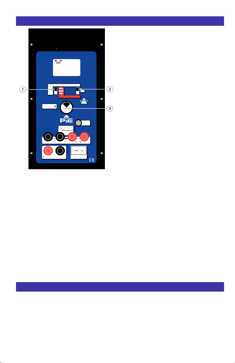
To start the Automatic Stepping
Start automatic stepping or ramping by placing
the EZ-CHECK Switch into the HI or LO position
then press and hold the eDIAL KNOB for 6
seconds (the word STORE will appear on the
display after 3 seconds and continue to press
the EZ-DIAL KNOB) until the word STEP
appears on the display. The word STEP will
appear on the display anytime the selected
automatic function is running. Stop the stepping
or ramping by again pressing and holding the e
DIAL KNOB for 3 seconds.