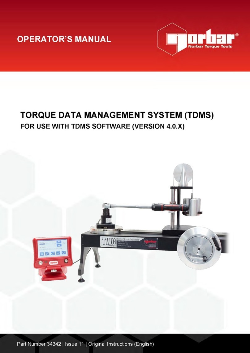
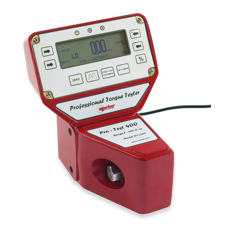
norbar TWC 400 AUTO User manual

OPERATOR’S MANUAL
TORQUE WRENCH CALIBRATOR (TWC)
TWC 400 & TWC 1500 - Auto
Part Number 34454 | Issue 1 | Original Instructions (English)
NORBAR TORQUE TOOLS LTD
Wildmere Road, Banbury,
Oxfordshire, OX16 3JU
UNITED KINGDOM
Tel + 44 (0)1295 270333
Email enquiry@norbar.com
NORBAR TORQUE TOOLS
45–47 Raglan Avenue, Edwardstown,
SA 5039
AUSTRALIA
Tel + 61 (0)8 8292 9777
Email enquiry@norbar.com.au
NORBAR TORQUE TOOLS INC
36400 Biltmore Place, Willoughby,
Ohio, 44094
USA
Tel + 1 866 667 2279
Email inquiry@norbar.us
NORBAR TORQUE TOOLS PTE LTD
194 Pandan Loop
#07-20 Pantech Business Hub
SINGAPORE 128383
Tel + 65 6841 1371
Email enquires@norbar.sg
NORBAR TORQUE TOOLS (SHANGHAI) LTD
91 Building-7F, No.1122 North Qinzhou Rd,
Xuhui District, Shanghai
CHINA 201103
Tel + 86 21 6145 0368
Email sales@norbar.com.cn
NORBAR TORQUE TOOLS INDIA PVT. LTD
Plot No A-168, Khairne Industrial Area,
Thane Belapur Road, Mahape,
Navi Mumbai – 400 709
INDIA
Tel + 91 22 2778 8480
Email enquiry@norbar.in
www.norbar.com
© Norbar Torque Tools Ltd 2018


1
CONTENTS
Part Numbers Covered by This Manual 2
TWC Markings 2
Safety 3
Introduction 4
Parts Included 4
Accessories 5
Features and Functions 6
Control Box 7
Set up Instructions 8
1. Locate TWC 8
2. Fitting the Guard 8
3. Connect Motor 9
4. Connect Temperature / Humidity Sensor 9
5. Connect Display 9
6. Connect USB Keyboard & Mouse (Optional) 9
7. Counter Balance Reaction Post Installation 9
8. Mount Transducer (not supplied with TWC) 11
9. Connect Power 12
10. Turn TWC On 13
11. Turn TWC Off 13
Operating Instructions 14
Locating a Torque Wrench 14
Exit TWC User Interface 16
Changing the Default Password 17
Timezone Setup 19
Time Setup 20
Configuring the Network 22
Printer Setup 25
Settings 31
Database 32
General Settings 33
Loader Calibration 34
How to Fill in Loader Calibration Page 35
How to Fill in Uncertainty Data 36
Certificate Settings 37
TWC Usage Overview 40
Add/Manage Template 41
Creating Certificates or Declarations of Conformance 46
How to Test a Type 1 Indication Tool 57
Adjustment Screen 64
Adjustment screen with Indicating Tools 66
Maintenance 67
Daily Checks 67
Torque Calibration 67
Temperature & Humidity Accuracy 67
Greasing Procedure 68
Disconnecting the Control Box for Calibration 69
Product Disposal 70
Specifications 71
EU Declaration of Conformity 72

2
Accessory Instructions 73
Square Adapters – 29214, 29215, 29216, 29217 73
Static Transducer Support Kit - 60318 73
Short Length Reaction Plate – 60319 74
FMT 25 Adaptor Kit - 60327 75
FMT Quick Release Kit – 60322 75
TWC Angle Offset Plate Kit – 60330 75
Trouble Shooting 76
Glossary of Terms 76
PART NUMBERS COVERED BY THIS MANUAL
This manual covers the set up and use of the Norbar TWC.
Part Number
Model
Torque Range
60312
TWC 400 AUTO
0 – 400 N·m
60313
TWC 1500 AUTO
0 – 1500 N·m
This product is intended for testing torque wrenches.
TWC Markings
Pictograms
Meaning
WARNING: LIVE PARTS INSIDE. DO NOT REMOVE COVER. NO USER
SERVICEABLE PARTS INSIDE.
Read and understand Operator’s Manual.
WARNING: READ ALL SAFETY WARNINGS AND ALL INSTRUCTIONS. FAILURE TO
FOLLOW THE WARNINGS AND INSTRUCTIONS MAY RESULT IN
ELECTRIC SHOCK, FIRE AND/OR SERIOUS INJURY.

3
SAFETY
• The TWC is designed for testing torque tools, do not use for other purposes.
• Always read and understand the Operator’s Manual fully before use.
• The TWC weighs up to 45 Kg. Take care when installing. Only lift by the solid metalwork.
• Ensure the operating area is capable of taking the weight of the TWC.
• This is a powerful torque application system. Care MUST be taken or damage may result to the torque
wrench, the torque measurement system, the TWC or injury to operating personnel.
• Do not block cooling air entry and exit points.
• Trapping hazard - Keep hands and loose clothing away from the torque wrench during use.
• To avoid damage to the torque wrench under test do not exceed the wrench set torque value.
• To avoid damage to the transducer do not exceed the maximum capacity.
• Never exceed the maximum torque capacity of the TWC.
• Do not operate without a torque measurement system connected and working.
• Ensure wrench guard is in position before using TWC.
• Ensure safety wire at the handle reaction point is in place.
• It is recommended that Portable Appliance Testing (PAT Testing), officially known as “In-Service
Inspection & Testing of Electrical Equipment” is completed at regular intervals, see MAINTENANCE
section for more information.

4
INTRODUCTION
The TWC Auto allows torque wrenches to be calibrated and tested in an accurate and repeatable way whilst
reducing operator effort.
This manual covers items 60312 & 60313 only.
The TWC Auto can automatically test all torque wrenches that operate on the ‘click-action’ or ‘cam-action’
principle, as well as manually testing dial type wrenches.
Parts Included
Description
Part Number
Quantity
TWC Auto 400 / 1500
60312 / 60313
1
TWC Counter Balance Reaction post assembly
62330
1
Display
62321
1
Display stand
62322
1
Power supply including power lead & plug
62323
1
Temperature & humidity sensor
62353
1
USB memory stick with manuals
61143
1
TWC Guard (and fixings)
62346
1
Maintenance grease kit
60325
1
Manual Drive Gear
62336
1

5
Accessories
Description
Image
Part Number
Static Transducer Support Kit
60318
Short Length Reaction Post
60319
Quick Release FMT Kit
60322
TWC FMT 25 Adapter plate
60327
3 Kg Mass Weight
60329
Angle Offset Plate
60330
Square Drive adapter 1” M to ¾” F
29214
Square Drive adapter 1” M to ½” F
29215
Square Drive adapter 1” M to ⅜” F
29216
Square Drive adapter 1” M to ¼” F
29217
TWC Hand Pendant
62328

6
FEATURES AND FUNCTIONS
• Allows torque wrenches to be calibrated or tested in accordance with BS EN 26789:2003, ISO 6789-1:2017
and ISO 6789-2:2017.
• Counterbalance reaction is designed to support the weight of the wrench so that the weight does not
become a parasitic force within the calibration system. The floating nature of the support means that the
wrench is able to find its own natural level rather than being constrained as in many other loading devices.
Any such constraint will be a parasitic force within the system. (Patents apply).
• Lightweight alloy construction ensures the TWC is easily transported, making it well suited for mobile
laboratory applications.
• Rotating transducer design ensures that the load is applied 90° to the torque wrench handle. The benefit of
this precise alignment is that forces are applied squarely to the load point of the handle.
• Supplied with a powerful yet simple touchscreen User Interface (UI) (keyboard and mouse also supported if
desired).
• Flexible tool template system; minimises number of templates required to cover a wide range of tools,
aiding efficient use.
• Programmable calibration workflow for each template, can be pre-set to ISO compliant flow for the given
tool for a faster set-up or can also support bespoke workflows.
• Calibration job management; book calibrations, track progress of previous bookings and resume them.
• Automated management of calibration and conformance workflows for non-indicating tools.
• Intelligent rate control system ensures fast cycling of tools while maintaining compliance with 2017
standards.
• Environmental monitoring (humidity/temperature) to ensure compliance with calibration standards.
• Automated management of uncertainty data for ISO 6789-2:2017 calibrations, guiding the user through the
process using dynamically generated instructions based on the current tool’s ISO classification and
workflow.
• Inbuilt data analysis and certification generation seamlessly move from calibration/conformance procedure
to certificate generation, no third-party software required.
• A substantial amount of inbuilt storage allowing for several years' worth of calibration data through normal
use.
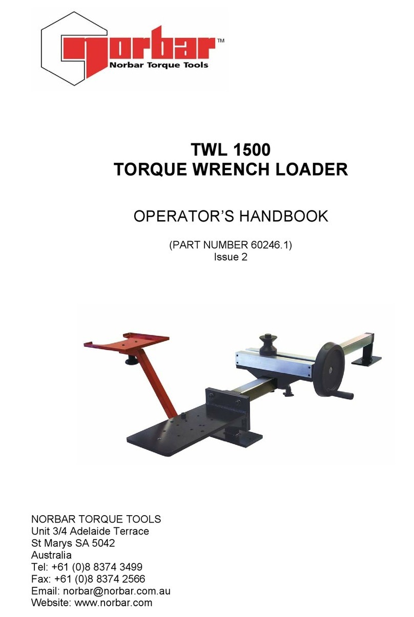
Emergency Stop
Guard (will stop
TWC if lifted)
Transducer
mounting
platform
Counter Balanced
Reaction post assembly
Guide rail
Control box (see
page 7)
Touchscreen
User Interface
Manual Drive
Gear input
FIGURE 1 – TWC Auto Features
7
Control Box
Front View
1. Transducer connector
2. Emergency stop
3. ON switch (Lights up RED when ON)
FIGURE 2 – Control Box Front View
Right View
1. Temperature & humidity sensor
2. Motor connector 1 for controls
3. Motor connector 2 for windings
4. Air outlet
FIGURE 3 – Control Box Right View
Rear View
1. Motor enable switch
2. Power connection
3. Touch screen power connector (USB)
4. Touch screen data connector (HDMI)
5. Network connector
6. 6 x USB connectors (Keyboard, mouse, camera, memory stick, etc)
FIGURE 4 – Control Box Rear View
Left View
1. Air inlet
FIGURE 5 – Control Box Left View
1
2
3
1
2
3
4
1
2
3
4
5
6
1

8
SET UP INSTRUCTIONS
NOTE: If the equipment is used in a manner not specified by the manufacturer, the protection
provided by the equipment may be impaired.
WARNING: ALLOW THE TWC TO EQUALISE TO THE AMBIENT TEMPERATURE /
HUMIDITY BEFORE SWITCHING ON. WIPE OFF ANY MOISTURE BEFORE
USE.
1. Locate TWC
WARNING: THE TWC WEIGHS UP TO 45 KG. ALWAYS USE TWO PEOPLE WHEN
LIFTING THE TWC.
Ensure location can cope with weight of loader.
Locate the TWC on a level surface at a comfortable working height.
2. Fitting the Guard
Insert two of the four shoulder bolts through the two holes in the guard and slide over the neoprene washer
as shown in Figure 6.
FIGURE 6 – Pairing the Neoprene Washers with Shoulder Bolts
Fasten the above to the two lower threaded holes on the TWC casing as shown in Figure 7. Use the
remaining two Shoulder Bolts to secure the guard to the radial slot and check it functions correctly by
opening and closing the guard, also shown in Figure 7.
FIGURE 7 – Fitting the Guard

9
3. Connect Motor
Plug motor wires in.
4. Connect Temperature / Humidity Sensor
Plug in temperature / humidity sensor to its dedicated connector.
5. Connect Display
Connect the display to ports 3 and 4 shown in Figure 4 on page 7.
6. Connect USB Keyboard & Mouse (Optional)
Connect keyboard to 1 of the 6 USB connectors.
Connect mouse to 1 of the 6 USB connectors.
7. Counter Balance Reaction Post Installation
Your TWC has been delivered with the reaction counter balance wheel assembly unattached to the reaction
assembly. This has been done to prevent damage to this assembly during transit.
FIGURE 8 – Disassembled Counter Balance Reaction Post Assembly

10
Place the counter balance wheel onto the top plate of the reaction assembly.
FIGURE 9 – Lining up the Counter Balance Reaction Wheel
Attach the counter balance wheel assembly with the two M4 socket cap screws from the underside of the top
plate of the reaction assembly. Tighten to 1 N·m.
FIGURE 10 – Attaching the Counter Balance Reaction Wheel
Assemble the weight carriage over the balance wheel.
FIGURE 11 – Counter Balance Reaction Assembly
Slide the “Counter Balance Reaction Post Assembly” on to the reaction rail.
NOTE: Shown for clockwise calibration, mount the opposite way for anti-clockwise calibration.
FIGURE 12 – Sliding the Counter Balance Reaction Assembly onto the Reaction Rail

11
Set the locking lever to engage positively when applied. This is done by pulling the lever towards you whilst
at the same time winding in the screw with an appropriate screwdriver. When at top dead centre, the lever
should start to engage to lock the reaction post’s position. Turn the lever to the right and you should start to
feel some resistance as the lock is engaged. Before continuing check the reaction post assembly is securely
fixed in position.
FIGURE 13 – Adjusting and Setting the Locking Lever
8. Mount Transducer (not supplied with TWC)
Select the correct capacity transducer and secure to the platform.
FMT Transducer
Directly mount with 3 fixings. Torque settings are 25 N·m for 400 and 85 N·m for 1500.
FIGURE 14 – Fitting an FMT Transducer
To save time when using multiple FMT transducers use the optional FMT quick release kit (Part number
60322) first (see page 75).
Static Transducer
Use optional static transducer kit ((Part number 60318) see page 73).
Place static transducer male square into the TWC.
Use optional adaptors (Part number 29214, 29215, 29216, 29217) as
required (see page 73); to reduce uncertainties these adaptors have been
manufactured to close fit tolerances.
Place support over transducer and secure to TWC with socket cap screws
provided.

12
9. Connect Power
WARNING: CHECK THAT THE POWER SUPPLY CORRESPONDS TO THE VOLTAGE
ON THE TWC RATING PLATE.
WARNING: THE TWC MUST BE EARTHED
ENSURE POWER SUPPLY HAS AN EARTH
DO NOT OPERATE WITHOUT AN EARTH
WARNING: FOR OPERATOR SAFETY ENSURE THE MAINS SUPPLY HAS A RESIDUAL
CURRENT DEVICE (RCD). TEST THE RCD REGULARLY.
Connect plug to local mains supply.
TIP: Use of a Different Local Supply Socket:
Should a different plug be required, the mains cable colours are:
BROWN-LIVE
BLUE-NEUTRAL
GREEN/YELLOW-EARTH
The new plug must have a ground (EARTH) connection.
If in doubt consult a qualified electrician.
If the plug has an internal fuse, a 2 amp value is recommended.

13
10. Turn TWC on
Turn on mains supply. Hold down the power pushbutton (See Figure 2.3 page 7) on the front until it lights up
red. Whilst you do this, the TWC will begin the power-on process.
When the process is complete, you will see the main TWC menu, as shown below:
At this point the TWC is fully powered but the motor electronics are not engaged. To do so, press the motor
enable pushbutton (See Figure 4.1 page 7). The button should glow blue and remain glowing. If the button
turns off after pressing it, check the emergency stop (See Figure 2.2 page 7) is not depressed, as this will
disable the motor electronics.
11. Turn TWC Off
The TWC can be turned off via the power icon on the main menu. Press the power icon and press the “shut
down” button in the confirmation pop-up.

14
OPERATING INSTRUCTIONS
Locating a Torque Wrench
Ensure the TWC Guard is lowered.
Use lowest capacity transducer to cover the range of the torque wrench to be tested.
NOTE: For a wrench with a push through ratchet, ensure the drive square is operating on the
correct side of the ratchet.
Ensure the transducer has been fitted with the correct adaptor and place the torque wrench drive into the
transducer. Ensure that the torque wrench drive is fully engaged (see Figure 15).
FIGURE 15 – Attaching a Torque Wrench
Set the reaction post position on the reaction arm so it is in the middle of the torque wrench handle (see Figure 16).
Use counter balance reaction (supplied) or optional short reaction post (Part number 60319) to suit wrench to be
tested.
FIGURE 16 – Locating a Torque Wrench
Counter balance the wrench by adding weights to the carriage until the wrench is sat horizontally.

15
FIGURE 17 – Adding Weights to the Counter Balance Reaction Assembly
If you push the reaction balancer up or down at the handle end the wrench should return to a true natural
horizontal position.
FIGURE 18 – Ensuring the Torque Wrench is in a Horizontal Position
Ensure the TWC is at the extreme minimum of start position (see Figure 19). The two dots to the edge of the
bearing housing denote the full travel. To get to the adjustment screen shown in Figure 19 you will first need to
ensure both a tool and template have been added (see pages 41 through to 50), from there you can access the
adjustment screen by selecting a tool and pressing the adjustment screen icon (see page 50).
FIGURE 19 – Making Sure the TWC is in the Home Position
Make sure the Guard is in position over the tool before loading.

16
Exit TWC User Interface
To perform initial setup of a TWC, or to change certain system-level settings, it may be necessary to leave
the TWC user interface. To exit the TWC UI, use the power button on the main menu and select “Exit to
Desktop”.

17
Changing the Default Password
The TWC is supplied with a default user password (“NorbarTWC”) which you should change for your
security. Once you change this, make sure you do not forget it; you may need to send the TWC back for
service if it is forgotten.
NOTE: To change the default password you will need to connect a USB keyboard to the TWC.
To set your own password, exit the TWC UI as described in the previous section, then open the menu bar
and select Preferences > Raspberry Pi Configuration
Next, type in the default password (“NorbarTWC”) in the password prompt.

18
Then in the window that appears, on the System tab, select “Change Password” and follow the onscreen
prompts to set a password of your own.
This manual suits for next models
3
Table of contents
Other norbar Test Equipment manuals

norbar
norbar ISO 1500 User manual

norbar
norbar Pro-Test 60 SERIES 2 User manual

norbar
norbar PRO-TEST 40 Service manual

norbar
norbar 80026 User manual

norbar
norbar T-Box 43236 User manual

norbar
norbar 43228 User manual

norbar
norbar TWL 1500 Service manual

norbar
norbar 43222 User manual

norbar
norbar TWC Series User manual

norbar
norbar TTT 3 Series Service manual