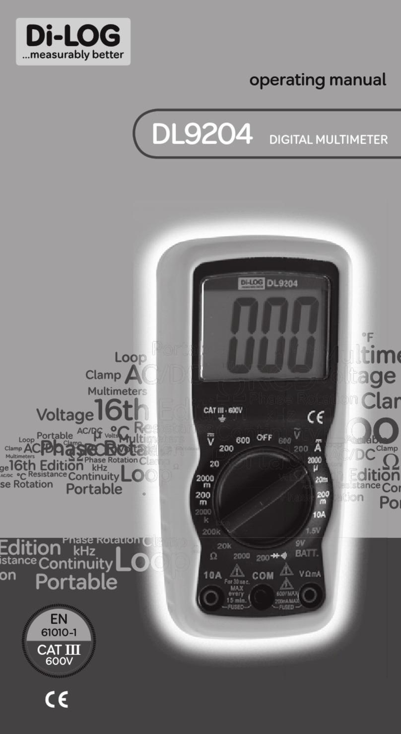
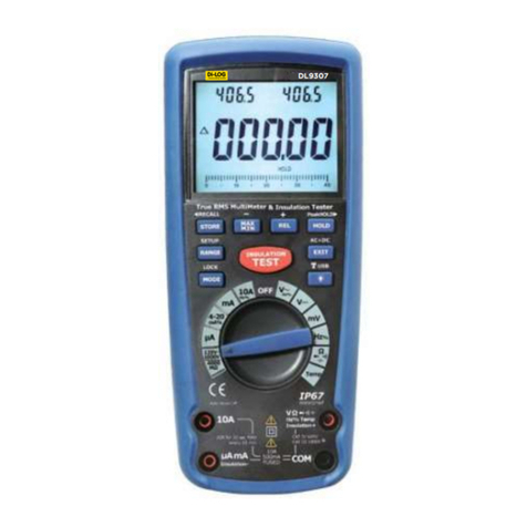
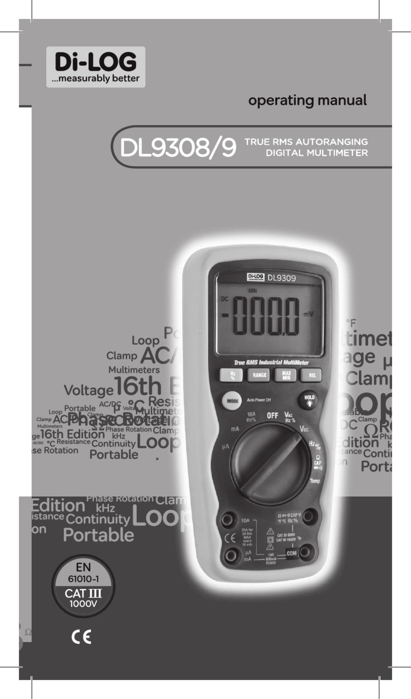
Dilog DL9205 User manual

Warranty & Maintenance
DL9205 AUTORANGING
MULTIMETER
operating manual
Di-Log Test Equipment
28 Wheel Forge Way,
Trafford Park,
Manchester
M17 1EH, UK
tel: + 44 161 87 7 0322 fax: + 44 161 877 1614
email: sales@dilog.co.uk website: www.dilog.co.uk
EN
61010-1
CAT III
600V

Safety Information
This manual contains information that must be
followed for operating the meter safely and
maintaining the meter in a safe operating condition.
If this meter is not used in the manner specied, the
protection provided may be impaired.
Warning! Warns of potential danger, refer to the
instruction manual to avoid personal injury or
damage to the meter.
Caution! Dangerous voltage. Danger of electrical
shock.
Continuous double or reinforced insulation
complies with IEC536, class II.
Symbol of conformity, conrms conformity with
relevant EU directives. The meter complies with
EMC directives (89/336/EEC). Specically stand-
ards EN 50081-1 and EN 50082-1 as well as the
Low Voltage Directive (73/23/EEC) described in
the standard EN 61010-1.

Safety Information Safety Information
The meter has been designed in accordance with
the safety regulations for electronic measuring
instruments, EN 61010-1, IEC 61010.
Voltages above 75V DC or 50V AC may constitute a
serious shock hazard.
Before using the meter check for physical damage to
the casing in particular around the connectors. If the
case is damaged do not use the meter.
Check the test leads for damaged insulation or
exposed metal. Check the leads for continuity.
Replace damaged leads with identical model or
specication before using the meter.
Where applicable use GS38 approved leads (not
supplied) these are available from Di-Log. When using
test leads keep ngers behind the nger guards.
Do not apply more than the rated voltage, as marked
on the meter between the terminals or between any
terminal and ground.

Safety Information
Before making a measurement ensure that the rotary
switch is set to the appropriate range. Do not turn the
rotary switch whilst making a measurement.
Use the appropriate terminals, function and range for
your measurements. If the value to be measured is
not known use the maximum measurement position
and reduce the range step by step until a satisfactory
reading is obtained.
Do not use or store the meter in an environment of
high temperature, humidity, fumes, vapour, gaseous,
inammable and strong magnetic eld. The perform-
ance and safety of the user may be compromised in
such circumstances.
Disconnect circuit power and discharge all high
voltage capacitors before testing resistance,
continuity, diodes, capacitance or current.
Before measuring current check the meters fuses and
turn off power to the circuit before connecting the
meter to the circuit.

Safety Information Safety Information
Replace the battery as soon as the low battery
indicator appears. If the battery is low the meter
may give false readings.
Turn the meter power off when not in use,. Remove
the battery if the meter is in use for a long period.
Constantly check the battery as it may have leaked.
A leaking battery will damage the meter.
The meter may only be opened by a qualied service
technician for calibration and repair.

Input Limits
Symbols and Annunciators
Continuity
BAT LowBattery
Diode
DATA HOLD DataHold
AUTO AutoRanging
AC AlternatingCurrentorVoltage
DC DirectCurrentorVoltage
Never apply voltage or current to the meter that exceeds
the specied maximum:
Function Maximum
V DC or V AC 600V DC, 600V AC
mA DC/AC 400mA DC/AC
A DC/AC 10A DC/AC
(30 seconds max every 15 minutes)
Frequency, Resistance, 250V DC/AC
Capacitance, Duty Cycle,
Diode test, Continuity
Temperature 250 V DC/AC

Input Limits
1. 4000 count Liquid Crystal Display with symbolic signs.
2. Function rotary switch.
3. 10A (positive) input jack for 10A DC or AC
measurements.
4. COM (negative) input terminal.
5. Positive input terminal.
6. MODE pushbutton.
7. Range pushbutton.
8. Data Hold pushbutton.
9. Relative pushbutton.
Controls and Inputs
1
2
3
8
9
5
6
7
4

Specications
The instrument complies with: EN61010-1.
Insulation: Class2, Double insulation.
Overvoltage category: CATIII 600V.
Display:
4000 counts LCD display with function indication.
Polarity: Automatic, (-) negative polarity indication.
Overrange: “OL” mark indication.
Low battery indication: The “BAT” is displayed when
the battery voltage drops below the operating level.
Measurement rate: 2 times per second, nominal.
Auto power off: Meter automatically shuts down after
approx. 15 minutes of inactivity.
Operating environment: 0˚C to 50˚C (32˚F to 122
˚F) at < 70 % relative humidity.
Storage temperature: -20˚C to 60˚C (-4˚F to 140˚F)
at < 80 % relative humidity.
For inside use, max height: 2000m
Pollution degree: 2
Power: One 9V battery , NEDA 1604, IEC 6F22.
Dimensions: 150 (H) x 70 (W) x 48 (D) mm
Weight: Approx.: 255g.
Accuracy is given at 18˚C to 28˚C (65˚F to 83˚F), less than 70 % RH

Specications Specications
DC Voltage (Auto-ranging)
Range Resolution Accuracy
400.0mV 0.1mV ±0.5% of rdg + 2 dgts
4.000V 1mV
40.00V 10mV ±1.2% of rdg + 2 dgts
400.0V 100mV
600V 1V ±1.5% of rdg + 2 dgts
Input Impedance: 7.8MΩ.
Maximum Input: 600Vdcor600Vacrms.
DC Current (Auto-ranging for uA and mA)
Range Resolution Accuracy
400.0uA 0.1uA ±1.0% of rdg + 3 dgts
4000uA 1uA
40.00mA 10uA ±1.5% of rdg + 3 dgts
400.0mA 100uA
10A 10mA ±2.5% of rdg + 5 dgts
Overload Protection: 0.5A/250Vand10A/250VFuse.
Maximum Input: 400mAdcor400mAacrmsonuA/mAranges,10Adcor
acrmson10Arange.
AC Voltage (Auto-ranging except 400mV)
Range Resolution Accuracy
400.0mV 0.1mV ±1.5%ofrdg+15dgts
4.000V 1mV ±1.2%ofrdg+3dgts
40.00V 10mV ±1.5%ofrdg+3dgts
400.0V 100mV
600V 1V ±2.0%ofrdg+4dgts
Input Impedance: 7.8MΩ.
Frequency Range: 50to400Hz.
Maximum Input: 600Vdcor600Vacrms.

Specications
AC Current (Auto-ranging for uA and mA)
Range Resolution Accuracy
400.0uA 0.1uA ±1.5% of rdg + 5 dgts
4000uA 1uA
40.00mA 10uA ±1.8% of rdg + 5 dgts
400.0mA 100uA
10A 10mA ±3.0% of rdg + 7 dgts
Overload Protection: 0.5A / 250V and 10A / 250V Fuse.
Frequency Range:50to400Hz.
Maximum Input: 400mAdcor400mAacrmsonuA/mAranges,10Adcor
acrmson10Arange.
Resistance (Auto-ranging)
Range Resolution Accuracy
400.0Ω 0.1Ω ±1.2% of rdg + 4 dgts
4.000kΩ 1Ω ±1.0% of rdg + 2 dgts
40.00kΩ 10Ω ±1.2% of rdg + 2 dgts
400.0kΩ 100Ω
4.000MΩ 1kΩ
40.00MΩ 10kΩ ±2.0% of rdg + 3 dgts
Input Protection: 250V dc or 250V ac rms.
Capacitance (Auto-ranging)
Range Resolution Accuracy
4.000nF 1pF ±5.0% of rdg+50 dgts
40.00nF 10pF ±5.0% of rdg + 7 dgts
400.0nF 0.1nF
4.000uF 1nF ±3.0% of rdg + 5 dgts
40.00uF 10nF
200.0uF 0.1uF ±5.0% of rdg + 5 dgts
Input Protection:250Vdcor250Vacrms.

Specications Specications
Frequency (Auto-ranging)
Range Resolution Accuracy
9.999Hz 0.001Hz
99.99Hz 0.01Hz ±1.5% of rdg + 5 dgts
999.9Hz 0.1Hz
9.999kHz 1Hz ±1.2% of rdg + 3 dgts
99.99kHz 10Hz
999.9kHz 100Hz
9.999MHz 1kHz ±1.5% of rdg + 4 dgts
Sensitivity: >0.5V RMS while ≤ 1MHz ;
Sensitivity: >3VRMSwhile>1MHz;
Overload protection: 250Vdcoracrms.
Duty Cycle
Range Resolution Accuracy
0.1%~99.9% 0.1% ±1.2% of rdg + 2 dgts
Pulse width: >100us,<100ms; Frequency width: 5Hz–150kHz
Sensitivity: >0.5VRMS Overload protection: 250Vdcoracrms.
Temperature
Range Resolution Accuracy
-20˚C~+760˚C 1˚C ±3% of rdg
-4˚F~+1400˚F 1˚F ±5˚C/9˚F
Sensor: Type K Thermocouple.
Overload protection: 250V dc or ac rms..

Specication
Audible continuity
Audible threshold: Less than 150Ω;
Test current: <0.3mA
Overload protection: 250V dc or ac rms.
Diode Test
Range Resolution Accuracy
0.3mA typical 1 mV ±10% of rdg + 5 dgts
Open circuit voltage: 1.5Vdctypical.
Overload protection: 250Vdcoracrms.

Specication
Warning:
RISK OF ELECTROCUTION. HIGH-VOLTAGE CIRCUITS,
BOTH AC AND DC, ARE VERY DANGEROUS AND
SHOULD BE MEASURED WITH GREAT CARE.
1. ALWAYS turn the function switch to the OFF
position when the meter is not in use. This meter
has Auto OFF that automatically shuts the meter
OFF if 15 minutes elapse between uses.
2. If “OL” appears in the display during a measure-
ment, the value exceeds the range you have
selected. Change to a higher range.
Note:
On some low AC and DC voltage ranges, with the
test leads not connected to a device, the display
may show a random, changing reading. This is
normal and is caused by the high-input sensitivity.
The reading will stabilize and give a proper
measurement when connected to a circuit.
Mode Button
To select Diode/Continuity , DC/AC Hz/% Duty
Operation

Operation
Range Button
Whenthemeterisrstturnedon,itautomatically
goesintoAutoRanging.Thisautomaticallyselectsthe
bestrangeforthemeasurementsbeingmadeand
isgenerallythebestmodeformostmeasurements.
Formeasurementsituationsrequiringthatarangebe
manuallyselected,performthefollowing:
1. PresstheRANGEbutton.The“AUTO”display
indicatorwillturnoff.
2. PresstheRANGEbuttontostepthroughthe
availablerangesuntilyouselecttherange
youwant.
3. PressandholdtheRANGEbuttonfor2seconds
toexittheManualRangingmodeandreturnto
AutoRanging.(Ifbacklightisturnedon,please
pressBACKLIGHTbuttonitwillturnoff).
Data Hold Button
TheDataHoldfunctionallowsthemeterto“freeze”a
measurementforlaterreference.
1. PresstheDATAHOLDbuttonto“freeze”the
readingontheindicator.Theindicator“HOLD”
willbeappearinthedisplay.
2. PresstheDATAHOLDbuttontoreturntonormal
operation.

Operation Operation
Relative Button
Therelativemeasurementfeatureallowsyoutomake
measurementsrelativetoastoredreferencevalue.
Areferencevoltage,current,etc.canbestoredand
measurementsmadeincomparisontothatvalue.
Thedisplayedvalueisthedifferencebetweenthe
referencevalueandthemeasuredvalue.
1. Performanymeasurementasdescribedinthe
operatinginstructions.
2. PresstheRELATIVEbuttontostorethereading
inthedisplayandthe“REL”indicatorwillappear
onthedisplay.
3. Thedisplaywillnowindicatethedifferencebe-
tweenthestoredvalueandthemeasuredvalue.
4. PresstheRELATIVEbuttontoreturntonormal
operation.

DC Voltage Measurements
Caution:
DO NOT MEASURE DC VOLTAGES IF A MOTOR ON
THE CIRCUIT IS BEING SWITCHED ON OR OFF. LARGE
VOLTAGE SURGES MAY OCCUR THAT CAN DAMAGE THE
METER.
1. SetthefunctionswitchtotheVDCposition
(“mV”willappearinthedisplay).
2. Inserttheblacktestleadbananaplugintothe
negative(COM)terminalandtheredtestlead
bananaplugintothepositive(V)terminal.
3. Connectthetestprobetipstothecircuitunder
test.Besuretoobservethecorrectpolarity(red
leadtopositive,blackleadtonegative).
4. Readthevoltageinthedisplay.Thedisplaywill
indicatetheproperdecimalpointandvalue.If
thepolarityisreversed,thedisplaywillshow(-)
minusbeforethevalue.

DC Voltage Measurements AC Voltage Measurements
Warning:
RISK OF ELECTROCUTION. THE PROBE TIPS MAY NOT
BE LONG ENOUGH TO CONTACT THE LIVE PARTS IN-
SIDE SOME 240V OUTLETS FOR APPLIANCES BECAUSE
THE CONTACTS ARE RECESSED DEEP IN THE OUTLETS.
AS A RESULT, THE READING MAY SHOW 0 VOLTS WHEN
THE OUTLET ACTUALLY HAS VOLTAGE ON IT. MAKE
SURE THE PROBE TIPS ARE TOUCHING THE METAL
CONTACTS INSIDE THE OUTLET BEFORE ASSUMING
THAT NO VOLTAGE IS PRESENT.
Caution:
DO NOT MEASURE AC VOLTAGES IF A MOTOR ON
THE CIRCUIT IS BEING SWITCHED ON OR OFF. LARGE
VOLTAGE SURGES MAY OCCUR THAT CAN DAMAGE
THE METER.
1. SetthefunctionswitchtotheVACposition.
2. Inserttheblacktestleadbananaplugintothe
negative(COM)terminalandtheredtestlead
bananaplugintothepositive(V)terminal.
3. Connectthetestprobetipstothecircuit
undertest.
4. Readthevoltageinthedisplay.Thedisplaywill
indicatetheproperdecimalpoint,valueand
symbol(AC,V,etc.)

DC Current Measurements
Caution:
DO NOT MAKE CURRENT MEASUREMENTS ON THE 10A
SCALE FOR LONGER THAN 30 SECONDS. EXCEEDING
30 SECONDS MAY CAUSE DAMAGE TO THE METER
AND/OR THE TEST LEADS.
1. Inserttheblacktestleadbananaplugintothe
negative(COM)terminal.
2. Forcurrentmeasurementsupto4000μADC,set
thefunctionswitchtotheμApositionandinsert
theredtestleadbananaplugintothe(μA)
terminal.
3. Forcurrentmeasurementsupto400mADC,
setthefunctionswitchtothemArangeand
inserttheredtestleadbananaplugintothe
(mA)terminal.
4. Forcurrentmeasurementsupto10ADC,setthe
functionswitchtotheApositionandinsertthe
redtestleadbananaplugintothe10Aterminal.
5. PresstheAC/DCbuttonuntil“DC”appearsinthe
display.

DC Current Measurements DC Current Measurements
6. Removepowerfromthecircuitundertest,
thenopenupthecircuitatthepointwhere
youwishtomeasurecurrent.
7. Connecttheblacktestprobetiptothe
negativesideofthecircuit.Connectthe
redtestprobetiptothepositivesideof
thecircuit.
8. Applypowertothecircuit.
9.Readthecurrentinthedisplay.Thedisplay
willindicatetheproperdecimalpoint,value
andsymbol.

AC Current Measurements
Warning:
TO AVOID ELECTRIC SHOCK, DO NOT MEASURE AC
CURRENT ON ANY CIRCUIT WHOSE VOLTAGE EXCEEDS
250V AC.
Caution:
DO NOT MAKE CURRENT MEASUREMENTS ON THE 10A
SCALE FOR LONGER THAN 30 SECONDS. EXCEEDING 30
SECONDS MAY CAUSE DAMAGE TO THE METER AND/OR
THE TEST LEADS.
1. Inserttheblacktestleadbananaplugintothenega-
tive(COM)terminal.
2. Forcurrentmeasurementsupto4000μAAC,setthe
functionswitchtotheμApositionandinsertthered
testleadbananaplugintothe(μA)terminal.
3. Forcurrentmeasurementsupto400mAAC,setthe
functionswitchtothemArangeandinsertthered
testleadbananaplugintothe(mA)terminal.
4. Forcurrentmeasurementsupto10AAC,setthe
functionswitchtotheApositionandinsertthered
testleadbananaplugintothe10Aterminal.
5. PresstheAC/DCbuttonuntil“AC”appearsinthe
display.
Table of contents
Other Dilog Multimeter manuals
Popular Multimeter manuals by other brands
Maxwell Digital Multimeters
Maxwell Digital Multimeters 25506 user manual
Extech Instruments
Extech Instruments MP510A user guide
Clarke
Clarke CDM80C operating instructions
Agilent Technologies
Agilent Technologies U1273A quick start guide

Hioki
Hioki DT4250 series Operation manual
MARTINDALE
MARTINDALE AM5 operating instructions
