Insulated Tip On
Insulated Tip Removed
3
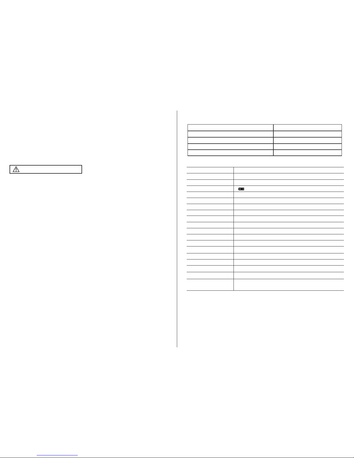
Potential danger. Indicates the user must refer to the manual for important safety information
Indicates hazardous voltages may be present
Equipment is protected by double or reinforced insulation
Indicates the terminal(s) so marked must not be connected to a circuit where the
voltage with respect to earth ground exceeds the maximum safety rating of the meter
MAX
600V
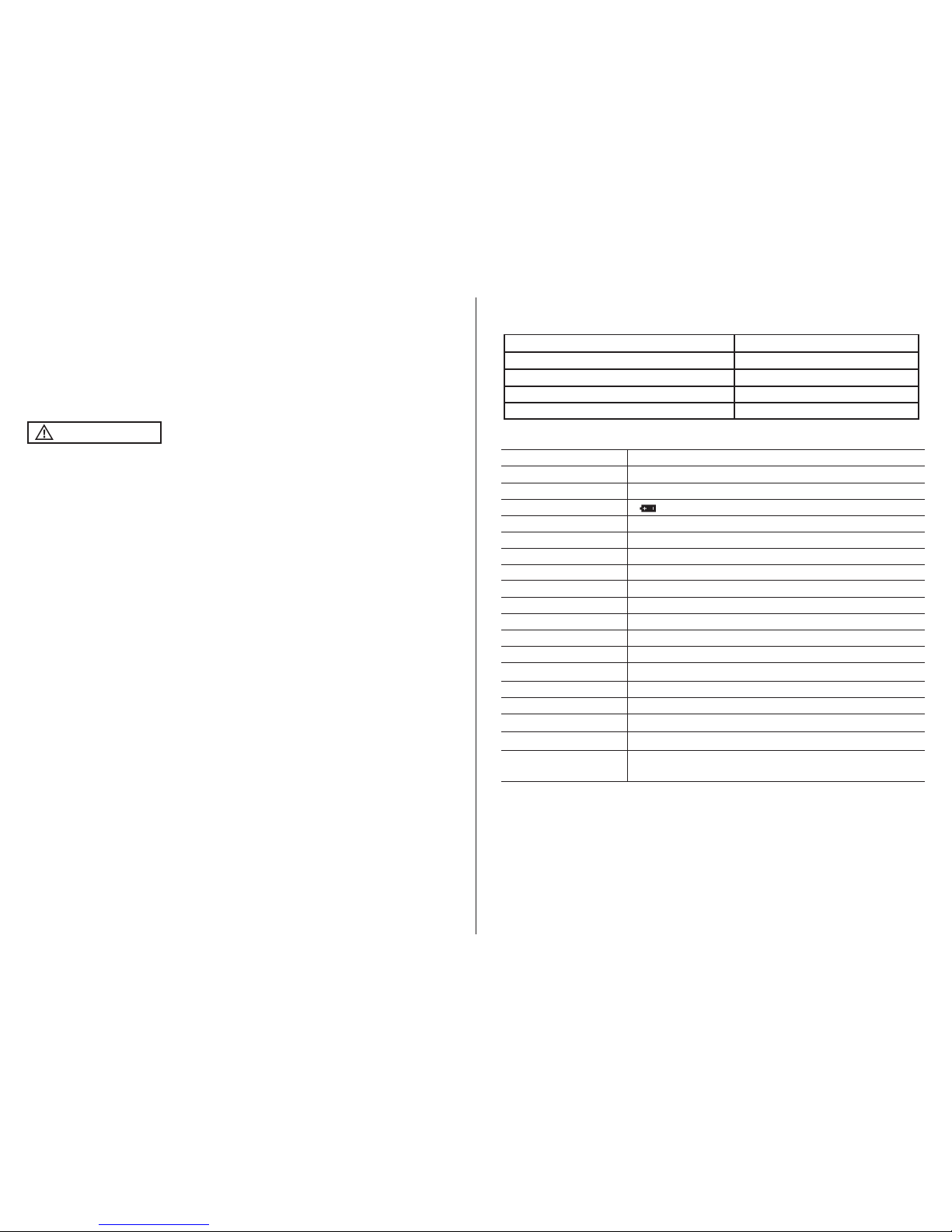
International Safety Symbols
Brief Description Typical Applications
Category Rating
Single phase receptacles
and connected loads
Three phase circuits and
single phase lighting
circuits in commercial
buildings
Connection point to
utility power and o
utdoor conductors
- Household appliances, power tools
- Outlets more than 30ft (10m) from a CAT III source
- Outlets more than 60ft (20m) from a CAT IV source
- Equipment in fixed installations such as 3-phase
motors, switchgear and distribution panels
- Lighting circuits in commercial buildings
- Feeder lines in industrial plants
- Any device or branch circuit that is close to a CAT III source
CAT II
CAT III
- Primary distribution panels
- Overhead or underground lines to detached buildings
- Incoming service entrance from utility
- Outdoor pumps
CAT IV
The measurement category (CAT) rating and voltage rating is determined by a combination of the meter, test probes and any accessories connected to
the meter and test probes. The combination rating is the LOWEST of any individual component.
Safety Category Ratings
WARNING:
Operation is limited to CAT II applications when the insulated tips are removed
from one or both test probes. Refer to Input Limits section in this manual for maximum voltage ratings.
Test Leads
CAT IV 600V
CAT III 1000V
CAT II
1000V
4
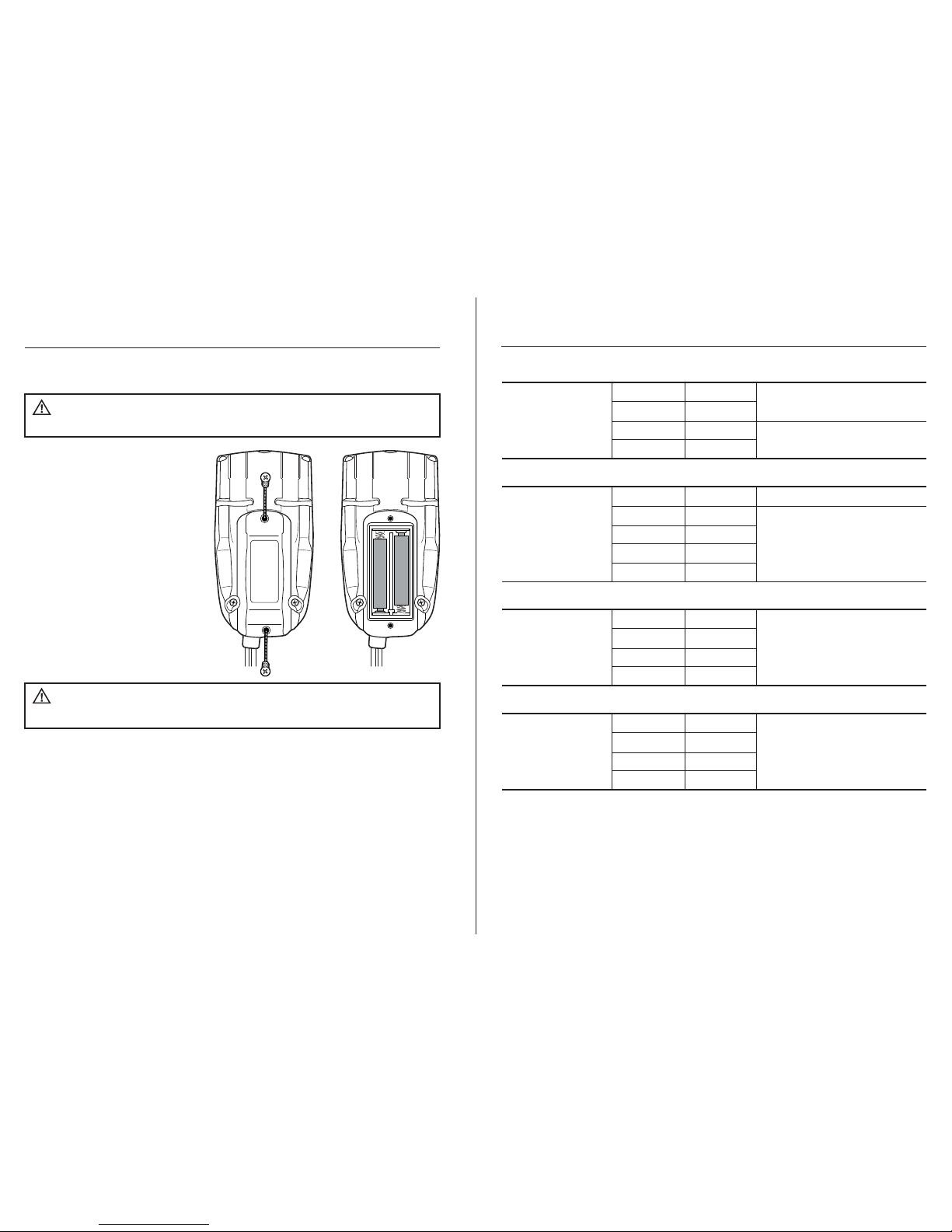
Maintenance
This Multimeter is designed to provide years of dependable service, if the
following care instructions are performed:
1. KEEP THE METER DRY. If it gets wet, wipe it off.
2. USE AND STORE THE METER IN NORMAL TEMPERATURES. Temperature
extremes can shorten the life of the electronic parts and distort or melt
plastic parts.
3. HANDLE THE METER GENTLY AND CAREFULLY. Dropping it can damage the
electronic parts or the case.
4. KEEP THE METER CLEAN. Wipe the case occasionally with a damp cloth.
DO NOT use chemicals, cleaning solvents, or detergents.
5. USE ONLY FRESH BATTERIES OF THE RECOMMENDED SIZE AND TYPE.
Remove old or weak batteries so they do not leak and damage the unit.
6. IF THE METER IS TO BE STORED FOR A LONG PERIOD OF TIME, the batteries
should be removed to prevent damage to the unit.
FCC COMPLIANCE
Users of this product are cautioned not to make modifications or changes that are not approved by
Southwire Company, LLC. Doing so may void the compliance of this product with applicable FCC requirements
and may result in the loss of the user’s authority to operate the equipment.
This device complies with Part 15 of the FCC rules and with RSS-210 of Industry Canada. Operation is subject to the
following two conditions: (1) This device may not cause harmful interference, and (2) This device must accept any
interference received, including interference that can cause undesired operation.
FCC Digital Emissions Compliance
This equipment has been tested and found to comply with the limits for a Class B digital device, pursuant to Part 15 of
the FCC Rules. These limits are designed to provide reasonable protection against harmful interference in a residential
installation. This equipment generates, uses and can radiate radio frequency energy and, if not installed and used in
accordance with the instructions, may cause harmful interference to radio communications. However, there is no
guarantee that interference will not occur in a particular installation. If this equipment does cause harmful interference
to radio or television reception, which can be determined by turning the equipment off and on, the user is encouraged
to try to correct the interference by one or more of the following measures:
• Reorient or relocate the radio or television receiving antenna.
• Increase the separation between the computer equipment and receiver.
• Connect the equipment into an outlet on a circuit different from that to which the radio or television receiver is connected.
• Consult the dealer or an experienced radio television technician for help.
Canadian Digital Apparatus Compliance
CAN ICES-3 (B)/NMB-3(B)