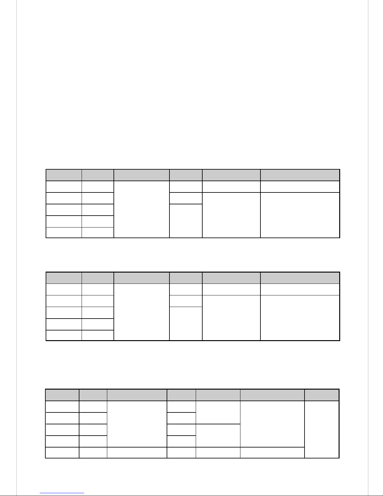
Kaise SK-4033 User manual

■Output Terminal
Connecting to the external inspection
equipment is possible by using the
equipped photoMOS relay output terminal.
BENCH-TOP DIGITAL MULTIMETER
INSTRUCTION MANUAL
CONTENTS
SK-4033 / SK-4035
1
1
2
2
3
4
4
6
6
7
9
9
11
12
13
14
14
15
15
16
17
17
18
18
FOR SAFETY MEASUREMENTS
1. UNPACKING AND INSPECTIONS
2. SPECIFICATIONS
2-1. General Specifications
2-2. Measurement Specifications
3. SAFETY PRECAUTIONS
3-1. Warnings
3-2. AC Adapter
3-3. General Warnings and Cautions
4. NAME ILLUSTRATION
5. MEASUREMENT PROCEDURES
5-1. Preparation for Use
5-2. Voltage Measurement
5-3. Resistance Measurement
5-4. Current Measurement
6. COMPARATOR FUNCTION
6-1. Comparator Settings
6-2. Buzzer Settings
6-3. Comparator Measurement
6-4. Comparator Relay Output
7. MAINTENANCE
7-1. Fuse Replacement
7-2. Periodical Check and Calibration
7-3. Repair
Thank you for purchasing KAISE MODEL
SK-4033/4035 BENCH-TOP DIGITAL
MULTIMETERS. To obtain the maximum
performance of this instrument, read this
Instruction Manual carefully, and take
safe measurement.
Features
■Comparator Function
Useful for the quality check in the
production line. Comparator relay output is
also possible by using the output terminal.
■True RMS
SK-4035 assures the accurate measurement
by True RMS.
422 Hayashinogo, Ueda City, Nagano Pref.,
386-0156 Japan
TEL : +81-268-35-1601 / FAX : +81-268-35-1603
E-mail : sales@kaise.com http://www.kaise.com

- 1 -
To prevent an electrical shock hazard to the operator and/or damage to the instruments, read this
instruction manual carefully before using the Insulation Tester. WARNINGS with the symbol
on the Insulation Tester and this instruction manual are highly important.
FOR SAFETY MEASUREMENTS
WARNING
Do not measure High Power Line (High Energy Circuits). High Power Line is
very dangerous and sometimes includes High Surge Voltage that could
cause explosive short in the instrument and could result in serious injury to
the operator. This instrument is for Low Power Line measurement. Even in
the Low Power Line, pay careful attention when measuring high voltage line.
The symbol listed in IEC 61010-1 and ISO 3864 means "Caution (refer to
instruction manual)".
The symbol in this manual advises the user of an electrical
shock hazard that could cause injury or material damages.
The symbol in this manual advises the user of an electrical
shock hazard that could result in serious injury or even death.
WARNING
CAUTION
1. UNPACKING AND INSPECTIONS
Confirm that the following items are contained in the package in good condition. If there is any
damage or missing items, ask your local dealer for replacement.
1. Bench-top Digital Multimeter
2. Test Lead (100-57)
3. AC Adapter (897)
4. Spare Fuse (0.5A/250V)
5. Instruction Manual
1 pce.
1 set
1 pce.
1 pce.
1 pce

- 2 -
2. SPECIFICATIONS
1. DISPLAY (LCD) :
(1) Main LCD
a. Numerical display :4000 count, maximum reading 4000, 21mm high
b. Units and symbols :
(2) Comparator setting LCD
a. Numerical display :Maximum reading 3999, 7.5mm high
b. Units and symbols : Bz on, H, G, L
2. OPERATING PRINCIPLE :Σ⊿ Conversion
3. AC MEASUREMENT :SK-4033 : Average rectification, SK-4035 : True RMS (AC coupling)
4. RANGE SELECTION :Auto range / manual range
5. FUNCTION SELECTION :Manual (key operation)
6. POLARITY:Auto ("−" symbol is shown in minus)
7. OVERLOAD WARNING :"OL" indication when exceeding the maximum reading
※see "4. Overload Warning" (p. 10) for details.
8. SAMPLING RATE :10 times/second
9. COMPARATOR :
10. DIELECTRIC STRENGTH :±500V DC (between COM terminal and ground)
11. OPERATING TEMPERATURE & HUMIDITY :
12. STORAGE TEMPERATURE & HUMIDITY :
-20℃to 60℃, 70%RH or less in non-condensin
g
13. TEMPERATURE COEFFICIENT :Accuracy at 23℃±5℃×0.2/℃
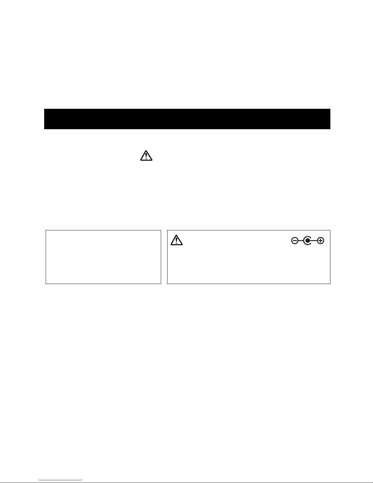
14. POWER SUPPLY :AC adapter
15. CURRENT CONSUMPTION:
2-1. General Specifications
AUTO, −, , 〜, Ω, kΩ, MΩ, mV, V, μA, mA, A,
and decimal point
a. Setting display :LCD (sub-display)
b. Setting method :Key operation
c. Setting range :−3999 to +3999
d. Test method :L <lower limit ≦G ≦higher limit <H
e. Comparator display :LED (L : red, G: green, H : red)
f. Comparator relay output :photoMOS relay
g. Buzzer :OFF・GO・LO・HI・HI and LO are selectable
Loading voltage : 250V DC, 250V AC MAX. / ON resistance : 35ΩMAX.
Continuous loading current : 120mA MAX.
Output terminal ※see "2. Dimensions of Recommended Solderless Terminal" (p. 16) for details.
Input : 100V to 240V AC, 50/60Hz
Output : 9V DC ※Switching type
Approx. 18mA or less (normal), approx. 32mA or less (comparator),
approx. 57mA or less (comparator & buzzer)
0℃to 35℃, 80%RH or less in non-condensing
35℃to 50℃, 70%RH or less in non-condensing

- 3 -
16. FUSE :
17. DIMENSIONS & WEIGHT :95(H)×200(W)×260(D)mm, approx. 1,140g
18. ACCESSORIES :
19. OPTIONAL ACCESSORIES :
2-2. Measurement Specifications
100-57 Test Lead, 897 AC Adapter, F31 Spare Fuse (0.5A/250V for μA/mA
terminal), Instruction Manual
660 AC/DC Clamp Adapter, 821 AC Clamp Adapter, 100-41
Test Lead Kit, 100-62 Test Lead Set, 940 Alligator Clip, 731
BNC Conversion Adapter
(23℃±5℃, <80%RH in non-condensing)
1. DC Voltage (DC. V)
Range
Resolution
Accuracy
Input resistance
Maximum input Overload protection
Range selection : auto range / manual range
400.0mV
4.000V
40.00V
400.0V
600V
±0.3%rdg±2dgt
0.1mV
1mV
10mV
100mV
1V
600V DC (for 10 sec.)
600V DC
600V DC, 450V AC rms for 1 min.
1000V DC
1000V AC rms
for 1 minute
2. AC Voltage (AC. V)
±1.0%rdg±5dgt
(50Hz to 500Hz)
SK-4033 : Average rectification / SK-4035 : True RMS
Range selection : auto range / manual range
※SK-4035 : Crest factor : 3:1 of the full scale (in 600V range, 3:1 at 300V or less)
Accuracy assured for the input of 5% or more of the full scale value.
>
100MΩ
≒11MΩ
≒10MΩ
Range
Resolution
Accuracy
Input resistance
Maximum input Overload protection
400.0mV
4.000V
40.00V
400.0V
600V
0.1mV
1mV
10mV
100mV
1V
600V AC (for 10 sec.)
600V AC rms
600V DC, 450V AC rms for 1 min.
1000V DC
1000V AC rms
for 1 minute
>
100MΩ
≒11MΩ
≒10MΩ
3. DC Current (DC. A)
400.0μA
4.000mA
40.00mA
400.0mA
10.00A
<0.05V
<0.25V
<0.1V
<0.6V
<0.5V
±0.75%rdg±2dgt
±1.5%rdg±2dgt
0.1μA
1μA
10μA
100μA
10mA
400μA DC
400mA DC
10A DC
0.5A/250V fuse
(input terminal)
3A/600V fuse (circuit)
10A/600V fuse (circuit)
Manual
Range
Resolution
Accuracy
Voltage drop
Maximum input
Overload protection
Range selection
10A range (p/n F30) : 10A/600V (φ6.3×32mm), μA/mA range (p/n F29) : 3A/600V (φ6.3×
32mm), power supply (p/n F31) : 0.5A/250V (φ5.2×20mm), μA/mA terminal (p/n F31) :
0.5A/250V (φ5.2×20mm)

- 4 -
SK-4033 : Average rectification / SK-4035 : True RMS
5. Resistance ( Ω)
400.0Ω
4.000kΩ
40.00kΩ
400.0kΩ
4.000MΩ
40.00MΩ
2.4V
1.2V
±0.3%rdg±3dgt
±0.3%rdg±2dgt
±1%rdg±2dgt
±3%rdg±4dgt
0.1Ω
1Ω
10Ω
100Ω
1kΩ
10kΩ
≦1.1mA
≦110μA
≦12.0μA
≦1.2μA
≦0.12μA
≦0.12μA
400V DC
280V AC rms
for 1 minute
※SK-4035 : Crest factor : 3:1 of the full scale
Accuracy assured for the input of 5% or more of the full scale value.
4. AC Current (AC. A)
400.0μA
4.000mA
40.00mA
400.0mA
10.00A
<0.05V
<0.25V
<0.1V
<0.6V
<0.5V
±1.5%rdg±6dgt
(50Hz to 500Hz)
0.1μA
1μA
10μA
100μA
10mA
400μA AC rms
400mA AC rms
10A AC rms
Auto /
Manual
0.5A/250V fuse
(input terminal)
3A/600V fuse (circuit)
10A/600V fuse (circuit)
Manual
Range
Resolution
Accuracy
Voltage drop
Maximum input Overload protection
Range selection
Range
Resolution
Accuracy
Max. open circuit voltage
Test current
Overload protection Range selection
3. SAFETY PRECAUTIONS
Correct knowledge of electric measurements is essential to avoid unexpected danger such as
operator's injury or damage to the instrument. Read the following precautions carefully for safety
measurements.
Before measurement, check if there are no damage to the instrument and the test leads. Dust,
grease and moisture must be removed.
3-1. Warnings
WARNING 1. Checks of the Instrument and Test Leads
WARNING 2. Prohibition of High Power Line Measurement
Do not measure High Power Line (High Energy Circuits) such as Distribution Transformers, Bus
Bars and Large Motors. High Power Line sometimes includes High Surge Voltage that could
cause explosive short in the instrument and could result in shock hazard. Generally, shock hazard
could occur when the current between the circuit, that involves more than 30V AC or 42.4V DC,
and ground goes up to 0.5mA or more.

- 5 -
Even for Low Power Circuits of electric/electronic appliances, such as heating elements, small
motors, line cords and plugs, High Voltage Measurements are very dangerous. To avoid electric
shock hazard, pay careful attention not to touch any part of the circuit.
WARNING 3. Warning for High Voltage Measurement
WARNING 4. Warning for Dangerous Voltage Measurement
●Do not hold the instrument in your hands.
●Keep safety distance from the circuit to be measured and the test leads not to touch the
dangerous voltage.
●Attach black and red alligator clips to the test lead pins.
●Turn off the circuit to be measured when connecting the test leads.
●After finishing the measurement, turn off the circuit to be measured again and discharge the
all capacitors. Then, detach alligator clips (test leads) from the circuit.
For dangerous high voltage measurement, strictly observe the warnings below (see Fig. 1).
In case of live-line measurement, strictly observe the warnings below (see Fig. 2) :
●Do not hold the instrument in your hands.
●Keep safety distance from the circuit to be measured not to touch the dangerous voltage.
●Black test lead : Attach black alligator clip and connect to −(earth) side of the circuit.
●Red test lead : Connect to +(positive) side of the circuit.
Alligator
Clips
Fig. 1
Red
Black
Fig. 2
Alligator Clip
Red
Black

- 6 -
Detach test leads from the measuring circuit and the input terminals when changing the
measurement function or removing the top case for fuse replacement.
WARNING 8. Test Lead Detachment
WARNING
CAUTION
WARNING 7. Maximum Input Observance
WARNING 6. Correct Function Settings
Children and the persons who do not have enough knowledge about
electric measurements must not use this instrument.
Do not measure the electricity in naked of barefooted to protect yourself
from electrical shock hazard.
Be careful not to get hurt with the sharp test lead pins.
Keep away the instrument from hot and humid conditions like in the car.
Do not apply hard mechanical shock or vibration.
Do not polish the case or attempt to clean it with any cleaning fluid like
gasoline or benzine. If necessary, use silicon oil or antistatic fluid.
WARNING 1.
WARNING 2.
WARNING 3.
CAUTION 1.
CAUTION 2.
3-3. General Warnings and Cautions
Do not measure any elements that might exceed the specified maximum input values of each
measurement ranges.
Always confirm that the correct measurement function is selected. Do not measure any voltage
except in the Voltage (V) function.
3-2. AC Adapter
Do not place high frequency welding machine or equivalent near the power source. The noise
might affect the instrument and would cause the mechanical error.
Read the following precautions carefully to prevent electric shock, fire accident, or damage to
the instrument
●Be sure to use with the specified power supply voltage.
●Insert the power plug and the connector fully into the each sockets.
●Do not pull the power cord when removing the power plug from the socket.
●Always keep the power plug and connector clean.
●Do not insert and remove the power plug and the connector with the wet hand.
●Do not damage, bend hardly, pinch, compress, or modify the power cord.
●Do not apply mechanical shock to the adapter part. Do not drop it off.
●Do not use the power cord that has any damage or melted coating.

- 7 -
Fig. 3
※Illustration shows SK-4035
Fig. 4
4-1. LCD
1. Main LCD
2. Comparator LCD
4. NAME ILLUSTRATION
AUTO
−
〜
:
:
:
:
Auto range
Minus
DC
AC
:
:
:
Units of resistance
Units of voltage
Units of current
Ω, kΩ, MΩ
mV, V
μA, mA, A
Higher limit Lower limit
Bz on
H
G
L
:
:
:
:
ON : buzzer ON / OFF : buzzer OFF
Buzzer when the measured value is higher than the higher limit.
Buzzer when the measured value is between higher and lower limits.
Buzzer when the measured value is lower than the lower limit.
FRONT PANEL
REAR PANEL
Main LCD
Power Switch Input Terminals
AC/DC Key RANGE Key
Function Keys
Comparator Output Terminals
AC Adapter Jack
Comparator LCD
△▽ Key
SET Key
COMP Key
Comparator LED
Key

- 8 -
4-2. Measurement Key Switches
4-3. Comparator Key Switch & LED
1. Power Switch
Press this switch to turn ON the instrument. Press it again to turn OFF.
1. △▽ Key
Press this key to set higher and lower limits, or to enter comparator setting mode.
3. SET Key
Press this key to enter comparator setting mode, or to fix the settings.
4. COMP Key
Press this key to start or finish the comparator measurement.
2. Key
Press this key to change the setting digit, or to enter comparator setting mode.
2. AC/DC Key
The key to change DC ⇔AC during voltage and current measurements. Default setting is DC.
4. Function Keys
Press one of these keys to select the measurement function.
3. RANGE Key : Range Hold
Manual-range measurement is possible by pressing this key during the auto-range measurement
in voltage and resistance measurements ("AUTO" disappears from LCD). To change the
measurement range in manual-range, press RANGE Key. Check decimal point and select the
suitable ranges.
To return to Auto-range : Press RANGE Key for 2 seconds or more. ("AUTO" lights up).
H (RED)
G (GREEN)
L (RED)
:
:
:
Lights up when the measured value is higher than the higher limit.
Lights up when the measured value is between higher and lower limits.
Lights up when the measured value is lower than the lower limit.
5. Comparator LED
The LED to show the comparator results.
4-4. Input Terminals
Insert black test lead to COM terminal and insert red test lead to other terminals depending on
the selected measurement functions.

- 9 -
4-5. Comparator Output Terminals
Comparator relay output is possible by connecting solderless terminals. For details, see "6-4.
Comparator Relay Output".
4-6. AC Adapter Jack
Connect the supplied AC Adapter to this jack.
5. MEASUREMENT PROCEDURES
1. Instruction Manual
Read INSTRUCTION MANUAL carefully to understand the specification and functions properly.
"3. SAFETY PRECAUTIONS" is very important for safety measurement.
2. AC Adapter
The power supply of this instrument is AC adapter. Connect the supplied "897 AC Adapter"
before starting the measurement.
5-1. Preparation for Use
AC Adapter Specification
Input : 100V to 240V AC, 50/60Hz
Output : 9V DC
※Switching type
The polarity of AC adapter for SK-4033/4035 is
"Center Plus". Be careful about this when using the
commercially available AC adapter.
Caution for the Polarity
3. Fuse
Current measurement ranges are protected by 0.5A/250V (for power supply & μA/mA terminal),
3A/600V (for μA/mA range) and 10A/600V (for 10A range) fuses. See "7-1. Fuse Replacement" for
their replacement.
4. Overload Warning
LCD shows "OL" when the measurement exceeds the maximum readings of each measurement
functions.
NOTE :
NOTE :
In 600V range, LCD shows "OL" when exceeding 1001 count. The display blinks when
the measurement value is from 600V to 1000V.
In 10A range, LCD shows "OL" when exceeding 2001 count. The display blinks when
the measurement value is from 10.01A to 20.00A.

- 10 -
The following symbol marks shown on the instrument and instruction manual are listed in IEC-
61010-1 and ISO 3864.
5. Symbol Mark
Warning and caution showing that the user should refer to instruction manual
Alternating Current (AC) Double Insulation
memo

- 11 -
5-2. Voltage Measurement ( V・〜V )
WARNING
●Do not measure high power line or high power circuit.
●Do not measure any voltage that might exceed the specified maximum input value.
●Before starting the measurement, check the voltage function is selected.
●Detach test leads from the measuring circuit when changing the measurement function.
●Read "3. SAFETY PRECAUTIONS" carefully to avoid electric shock hazard and serious
damage to the instrument.
Insert black test lead to COM terminal and insert red test lead to V-Ωterminal.
Turn on the instrument, or press V Key when moving from the other functions.
Press AC/DC Key to select DC ( ) or AC (〜).
NOTE :
Connect black test lead to −(earth) side of the circuit to be measured and connect red test
lead to +(positive) side.
NOTE : Connect the instrument IN PARALLEL to the circuit.
NOTE : Use alligator clips for dangerous voltage measurement.
Read the measurement value on LCD.
Detach the test lead from the circuit and turn off the instrument.
1.
2.
3.
4.
5.
6.
Display drifting would occur due to the high internal resistance of the instrument,
but it does not affect the instrument.
Available Functions : Comparator, Range hold
Black
Red
Press
V Key
Power-on
Fig. 5

- 12 -
Black
Red
Press
ΩKey
Power-on
Fig. 6
5-3. Resistance Measurement ( Ω)
●Before starting the measurement, check the Ωfunction is selected.
●Do not measure any voltage in resistance measurement function to avoid electric shock
hazard and serious damage to the instrument.
●Detach test leads from the measuring circuit when changing the measurement function.
●When measuring in-circuit resistance, turn off power to the circuit being measured and
discharge the all capacitors.
●Read "3. SAFETY PRECAUTIONS" carefully to avoid electric shock hazard and serious
damage to the instrument.
Insert black test lead to COM terminal, and insert red test lead to V-Ωterminal.
Turn on the instrument and press ΩKey.
If the resistor to be measured is connected in the circuit, turn off the circuit and discharge the
all capacitors.
Disconnect one side of the resistor to be measured and connect test leads to the both side.
Read the measurement value on LCD.
Detach the test lead from the circuit and turn off the instrument.
1.
2.
3.
4.
5.
6.
Available Functions : Comparator, Range hold
WARNING
When measuring in 4MΩrange or higher, external noise might affect the measurement and
might drift the display. TO prevent this problem, we recommend to use the shielded wires
instead of the supplied test leads. Using the wire with BNC connector is also possible by using
"731 BNC conversion adapter" (option).
Important Note for Resistance Measurement

- 13 -
5-4. Current Measurement ( A・〜A )
●Do not measure high power line or high power circuit.
●Do not measure any current that might exceed the specified maximum input value.
●Before starting the measurement, check the correct current function is selected.
●Do not measure any voltage in current measurement function to avoid electric shock
hazard and serious damage to the instrument.
●Detach test leads from the measuring circuit when changing the measurement function.
●Read "3. SAFETY PRECAUTIONS" carefully to avoid electric shock hazard and serious
damage to the instrument.
●Insert RED test lead to 10A terminal when measuring 10A range.
Insert black test lead to COM terminal and insert red test lead to μA/mA or 10A terminal.
NOTE : Insert RED test lead to 10A terminal when measuring 10A range.
Turn on the instrument.
Press one of the 400μA, 4mA, 40mA, 400mA, or 10A Keys, and select the
suitable measurement range.
Press AC/DC Key to select DC ( ) or AC (〜).
Turn off the circuit to be measured. Open the circuit after discharging the capacitors.
Connect black test lead to −(earth) side of the circuit to be measured and connect red test
lead to +(positive) side.
NOTE : Connect the instrument IN SERIES to the circuit.
NOTE : Use alligator clips for dangerous current measurement.
Turn on the circuit to be measured and read the measurement value on LCD.
Turn off the circuit and discharge the all capacitors.
Detach the test lead from the circuit and turn off the instrument.
1.
2.
3.
4.
5.
6.
7.
8.
9.
WARNING
Available Functions : Comparator
Black
Red
Insert RED test lead when
measuring 10A range.
Press one of these keys and
select the measurement range.
Power-on
Fig. 7
To the circuit
to be measured

- 14 -
Move to left digit
Press one of these keys to enter
comparator setting mode.
Blinking
Setting digit (blinking)
Press them to move the setting digit.
△:Up (1→2・・・) ▽:Down (9→8・・・)
Moved to left (blinking)
Move to right digit
Use △▽ Key to set −
All light up
Press to fix
the settings.
Fig. 8
6. COMPARATOR FUNCTION
What is Comparator Function?
The function useful to check GOOD/FAIL test result under the certain threshold. You can
check the result by buzzer and LED in accordance with the preset higher and lower limit.
SK-4033/4035 is also capable of comparator relay output by using the solderless terminal.
6-1. Comparator Settings
Turn on the instrument.
Enter the comparator setting mode by pressing one
of the △▽, , or SET Keys. Right digit of "Lo"
side of the comparator LCD blinks.
Press △▽ Keys and set the necessary number.
Keep it pressing for 2 seconds or more to speed-up.
Press Keys to move the setting digit to left
or right. The setting digit is blinking.
Press △▽ Keys to select minus (−).
Repeat the steps of 3 to 5, and set higher, lower
or both limits.
NOTE : Setting range is 3999 to−3999.
NOTE : The comparator condition can be
selected from the following.
Press SET Key to fix the comparator settings.
1.
2.
3.
4.
5.
6.
7.
△
△
①Measured value is higher than the higher limit.
②Measured value is between higher and lower limits.
③Measured value is lower than the lower limit.
△
△
Important Notes for Comparator Settings
●The all LEDs light up in the comparator setting mode.
●The keys except for △▽, , and SET keys do not work in the comparator setting mode.
●The comparator setting should be Higher limit (Hi)>Lower limit (Lo).
△
△

- 15 -
①Buzzer sounds when "G" lights up.
②Buzzer sounds when "L" lights up.
③Buzzer sounds when "H" lights up.
④Buzzer sounds when "H" or "L" lights up.
⑤Buzzer OFF (LED indication only)
No
Display
Press
to
change
Higher than the higher limit.
Between higher and lower limits.
Lower than the lower limit.
Fig. 9
Fig. 10
Buzzer sound
Red
Black
Press for 2 sec.
↓
Buzzer setting mode
ON/OFF
Press
6-2. Buzzer Settings
Enter buzzer setting mode by pressing COMP
Key for 2 seconds or more.
Press COMP Key and select buzzer timing from
①to ⑤shown in fig. 9.
NOTE : Default setting is ①.
Press COMP Key again for 2 seconds or more to
fix the buzzer setting and to return to the normal
measurement mode.
1.
2.
3.
6-3. Comparator Measurement
Press COMP Key after setting threshold and
buzzer timing. Comparator measurement is
started.
NOTE :
Buzzer and LED show the test result according to
the preset higher or lower limits.
Press COMP Key to finish the comparator
measurement.
1.
2.
3.
H (red) : measurement is higher than the higher limit.
G (green) : measurement is between higher and lower limits.
L (red) : measurement is lower than the lower limit.
The instrument is set to "manual range"
in comparator measurement ("AUTO"
disappears from LCD). The range is
fixed where the COMP Key is pressed.
Select the appropriate range before
pressing the key when necessary.
Buzzer timing can be selected as needed.
L <Lower Limit ≦G ≦Higher Limit <H
Important Notes for Comparator Measurement
●Comparator measurement should be finished automatically by the following operations.
- Measurement function is changed.
- AC/DC or RANGE Keys are pressed.
●Comparator test speed is the same as the display sampling speed (10 times/second).
●The instrument remains set to "manual range" after finishing the comparator measurement. To
measure in "auto range", press RANGE Key for 2 seconds or more until "AUTO" sign is
displayed on LCD.

- 16 -
Connect solderless terminal to the output terminal
on the rear panel to output the comparator result.
NOTE : See the connecting diagrams in fig. 12 when
using the relay output.
NOTE : Do not apply the loading that might exceed
the relay specification.
6-4. Comparator Relay Output
2. Dimensions of Recommended Solderless Terminal
Relay specification
L
oading voltage : 250V DC, 250V AC MAX.
ON resistance : 35ΩMAX.
Continuous loading current : 120mA MAX.
1. Connecting Diagram
①AC/DC Loading ②DC Loading (1)
+
+
−VL
(AC/DC)
Load
+
+
−
+
−
VL (DC)
③DC Loading (2)
+
+
−
+
+
−
VL (DC)
VL (DC)
Load Load
Load
NOTE : Sum of continuous load current
must not exceed the maximum
rating.
①Circle-shaped terminal ②Y-shaped (tip open type) terminal
●When taking the comparator measurement with the input terminals are opened, such as when
the resistance measurement, comparator always shows "Hi" result with "OL" sign on LCD. To
prevent this problem, add GO/STOP signal to your inspection system in reference to the circuit
diagram shown in Fig. 11.
※Reference circuit diagram
(in case of DC)
+
+
−
+
−
VL (DC)
Loading
Contact point like magnet relay
Fig. 11
Fig. 12
Fig. 13
Important Note for Comparator Measurement
Your inspection
system
GO/STOP signal from your inspection system
※Run the comparator when it is ON.
3.2
5.5
0.8
5.6 4.8
13.2
3.4
1.7 1.7
5.8
3.2
0.8
15.8
6.3 4.8
3.4

- 17 -
Fig. 14
Fig. 15
10A/600V
3A/600V
Rear Panel
Front Panel
Legs
(remove)
Stand
0.5A/250V
Press the terminal and
turn it to the left.
Pull out the terminal with
the fuse inside.
0.5A/250V
Fuse
7-1. Fuse Replacement
1. Internal Fuses
※10A range (F30) : 10A/600V (φ6.3×32mm), μA/mA range (F29) : 3A/600V(φ6.3×32mm), Power supply (F31) : 0.5A/250V(φ5.2×20mm)
7. MAINTENANCE
●To avoid electrical shock hazard, finish the measurement when to replace the fuse.
●Detach test leads from measuring circuit and input terminals and disconnect AC Adapter
from power source.
●Always use the specified fuse. Do not use this instrument shorting fuse holder or
without using the fuse.
Detach test leads from measuring circuit and
input terminals and disconnect AC Adapter
from power source.
Remove 4-screws from the legs on the
bottom case and remove 2-legs on rear
panel side.
Remove the top case.
Replace the blowout fuse into the new one.
NOTE : Verify that the correct rating fuse is
used.
Fix the top case and the removed legs and
tighten the screws.
1.
2.
3.
4.
5.
2. μA/mA Terminal Fuse ※0.5A/250V (φ5.2×20mm)…F31
Detach test leads from measuring circuit and
input terminals and disconnect AC Adapter
from power source.
Press μA/mA terminal and turn it to the left.
Pull out the terminal with the blowout fuse
inside.
NOTE : Use tweezers if the fuse is left in the
front panel.
Replace the blowout fuse into the new one.
Turn the terminal to the right until it is
locked.
1.
2.
3.
4.
WARNING

- 18 -
SK-4033/4035 is warranted in its entirety against any defects of material or workmanship under
normal use and service within a period of one year from the date of purchase of the original
purchaser. Warranty service is available at KAISE AUTHORIZED SERVICE AGENCY through
your local dealer. Their obligation under this warranty is limited to repairing or replacing SK-
4033/4035 returned intact or in warrantable defect with proof of purchase and transport charges
prepaid. KAISE AUTHORIZED DEALER and the manufacturer, KAISE CORPORATION, shall not
be liable for any consequential damages, loss or otherwise. The foregoing warranty is exclusive
and in lieu of all other warranties including any warranty of merchantability, whether expressed
or implied.
This warranty shall not apply to any instrument or other article of equipment which shall have
been repaired or altered outside of KAISE AUTHORIZED SERVICE AGENCY, nor which have
been subject to misuse, negligence, accident, incorrect repair by users, or any installation or use
not in accordance with instructions provided by the manufacturer.
Periodical check and calibration is necessary to make safety measurements and to maintain the
specified accuracy. The recommended check and calibration term is once a year and after the
repair service. This service is available at KAISE AUTHORIZED SERVICE AGENCY through your
local dealer.
Repair service is available at KAISE AUTHORIZED SERVICE AGENCY through your local dealer.
Pack the instrument securely with your name, address, telephone number and problem details,
and ship prepaid to your local dealer.
Check the following items before asking repair service.
●Check if the AC adapter is connected to the instrument and the outlet.
●Check if the fuses do not blow out or not drop off from the fuse holder.
●Confirm that the correct measurement function is selected.
●Confirm if the over input, exceeding the specified range value, is not applied.
●Confirm that measured accuracy is adopted in the operating environment.
●Confirm that the body of this instrument and test leads have no cracks or any other damages.
●Check if the instrument is not affected by the strong noise generated from the equipment to
be measured or measuring surroundings.
7-2. Periodical Check and Calibration
7-3. Repair
WARRANTY

70-1201-4033-1 1003
Product specifications and appearance are subject to change without notice due to continual improvements.
KAISE AUTHORIZED DEALER
422 Hayashinogo, Ueda City, Nagano Pref., 386-0156 Japan
TEL : +81-268-35-1601 / FAX : +81-268-35-1603
This manual suits for next models
1
Table of contents
Other Kaise Multimeter manuals