manuals.online logo
Brands
  1. Home
  2. •
  3. Brands
  4. •
  5. Dimplex
  6. •
  7. Heat Pump
  8. •
  9. Dimplex System M Compact Plus C 6kW User guide

Dimplex System M Compact Plus C 6kW User guide

This manual suits for next models

2

Other Dimplex Heat Pump manuals

Dimplex LA 11PS User manual

Dimplex

Dimplex LA 11PS User manual

Dimplex WIH 120TU User guide

Dimplex

Dimplex WIH 120TU User guide

Dimplex SI 75TER+ User manual

Dimplex

Dimplex SI 75TER+ User manual

Dimplex SI 90TU User guide

Dimplex

Dimplex SI 90TU User guide

Dimplex SI 6TU User manual

Dimplex

Dimplex SI 6TU User manual

Dimplex SI 5MER User manual

Dimplex

Dimplex SI 5MER User manual

Dimplex LAJ 11MUR User manual

Dimplex

Dimplex LAJ 11MUR User manual

Dimplex LA 9S-TU User manual

Dimplex

Dimplex LA 9S-TU User manual

Dimplex LBW 300 User manual

Dimplex

Dimplex LBW 300 User manual

Dimplex SI 130TUR+ User manual

Dimplex

Dimplex SI 130TUR+ User manual

Dimplex SI 5US User manual

Dimplex

Dimplex SI 5US User manual

Dimplex LA 20AS User manual

Dimplex

Dimplex LA 20AS User manual

Dimplex LA 9K User manual

Dimplex

Dimplex LA 9K User manual

Dimplex WI 9 TE User manual

Dimplex

Dimplex WI 9 TE User manual

Dimplex WI 10TU User manual

Dimplex

Dimplex WI 10TU User manual

Dimplex WI 22 TE User manual

Dimplex

Dimplex WI 22 TE User manual

Dimplex DHW 300+ User manual

Dimplex

Dimplex DHW 300+ User manual

Dimplex LIKI 14TE User manual

Dimplex

Dimplex LIKI 14TE User manual

Dimplex LA 9TU User manual

Dimplex

Dimplex LA 9TU User manual

Dimplex LIK 8TES User manual

Dimplex

Dimplex LIK 8TES User manual

Dimplex SI 130TE User manual

Dimplex

Dimplex SI 130TE User manual

Dimplex A-Class User manual

Dimplex

Dimplex A-Class User manual

Dimplex LA 60TU Operating instructions

Dimplex

Dimplex LA 60TU Operating instructions

Dimplex LA 9TU User manual

Dimplex

Dimplex LA 9TU User manual

Popular Heat Pump manuals by other brands

Daikin RXL12QMVJU Service manual

Daikin

Daikin RXL12QMVJU Service manual

AIREDALE BluCube CUR092V16-1CO-0 Installation and maintenance manual

AIREDALE

AIREDALE BluCube CUR092V16-1CO-0 Installation and maintenance manual

Calyenty RBH 125 Customer's manual

Calyenty

Calyenty RBH 125 Customer's manual

GRE HPGI50 owner's manual

GRE

GRE HPGI50 owner's manual

Carrier 30XW Installation, operation and maintenance instructions

Carrier

Carrier 30XW Installation, operation and maintenance instructions

Hayward SUMHEAT HP5131DT3 Installation instructions manual

Hayward

Hayward SUMHEAT HP5131DT3 Installation instructions manual

REMKO SQW 400 Electrical wiring

REMKO

REMKO SQW 400 Electrical wiring

Sanyo SAP120FCH Service manual

Sanyo

Sanyo SAP120FCH Service manual

Daikin EHYHBH05AA Operation manual

Daikin

Daikin EHYHBH05AA Operation manual

Panasonic WH-SDF03E3E5 Design handbook

Panasonic

Panasonic WH-SDF03E3E5 Design handbook

Airxcel 45000 Series Installation, operation and maintenance instructions

Airxcel

Airxcel 45000 Series Installation, operation and maintenance instructions

Mitsubishi Electric PUZ-SWM60VAA Service manual

Mitsubishi Electric

Mitsubishi Electric PUZ-SWM60VAA Service manual

Carrier WSHP Open v3 Integration guide

Carrier

Carrier WSHP Open v3 Integration guide

Mitsubishi Electric EHSE-YM9EC Service manual

Mitsubishi Electric

Mitsubishi Electric EHSE-YM9EC Service manual

TGM CTV14CN018A Technical manual

TGM

TGM CTV14CN018A Technical manual

Carrier 38MGQ Series installation instructions

Carrier

Carrier 38MGQ Series installation instructions

Kokido K2O K880BX/EU Owner's manual & installation guide

Kokido

Kokido K2O K880BX/EU Owner's manual & installation guide

Viessmann VITOCAL 300-G PRO Type BW 2150 Installation and service instructions

Viessmann

Viessmann VITOCAL 300-G PRO Type BW 2150 Installation and service instructions

manuals.online logo
manuals.online logoBrands
  • About & Mission
  • Contact us
  • Privacy Policy
  • Terms and Conditions

Copyright 2025 Manuals.Online. All Rights Reserved.

Order no.: DOK4x HCIAO WxDEN EN · FD 9912
System M
Compact Plus C 6kW
Installation and
Operating Instruction
Air-to-Water
Heat Pump
in Integral Design
Glen
Dimplex
Thermal
Solutions
Dimplex
06CHCIAOC6
06IHCIAOC6
www.gdts.one DOK4x HCIAO WxDEN · FD 9912 1
Air-to-water heat pump 6 kW with cooling English
Table of contents
1 Please read immediately...................................................................................................................................3
1.1 Intended use............................................................................................................................................................................. 3
1.2 Legal regulations and directives ........................................................................................................................................ 3
1.3 Energy-efficient use of the heat pump............................................................................................................................ 3
2 Intended use of the heat pump ......................................................................................................................4
2.1 Area of application.................................................................................................................................................................. 4
2.2 Operating principle................................................................................................................................................................. 4
3 Scope of supply ..................................................................................................................................................5
3.1 Indoor unit ................................................................................................................................................................................. 5
3.2 Outdoor unit.............................................................................................................................................................................. 6
4 Transport..............................................................................................................................................................7
4.1 Outdoor unit.............................................................................................................................................................................. 7
4.2 Indoor unit ................................................................................................................................................................................. 7
4.3 Removing the refrigeration circuit .................................................................................................................................... 8
5 Installation ...........................................................................................................................................................9
5.1 Outdoor unit.............................................................................................................................................................................. 9
5.2 Indoor unit ...............................................................................................................................................................................10
5.3 Acoustic emissions...............................................................................................................................................................10
6 Assembly / connection.................................................................................................................................. 11
6.1 Assembly of the refrigerant line and electric wire .....................................................................................................11
6.2 Condensate drain..................................................................................................................................................................11
6.3 Connection on heating side ..............................................................................................................................................11
6.4 Domestic hot water connection ......................................................................................................................................12
6.5 Temperature sensor connection .....................................................................................................................................13
6.6 Electrical connection ...........................................................................................................................................................14
6.7 Refrigerant pipe connections ...........................................................................................................................................17
7 Commissioning ................................................................................................................................................ 20
7.1 General......................................................................................................................................................................................20
7.2 Preparation..............................................................................................................................................................................20
7.3 Procedure ................................................................................................................................................................................20
8 Cleaning / maintenance ................................................................................................................................ 21
8.1 Maintenance ...........................................................................................................................................................................21
8.2 Cleaning the indoor unit .....................................................................................................................................................21
8.3 Cleaning the domestic hot water cylinder....................................................................................................................21
8.4 Cleaning the outdoor unit ..................................................................................................................................................21
9 Faults / troubleshooting................................................................................................................................ 22
10 Decommissioning / disposal ........................................................................................................................ 22
11 Device information ......................................................................................................................................... 23
12 Dimension drawing......................................................................................................................................... 25
12.1 Dimension drawing outdoor unit.....................................................................................................................................25
12.2 Dimension drawing indoor unit ........................................................................................................................................26
12.3 Dimension drawing legend................................................................................................................................................27
13 Diagrams ........................................................................................................................................................... 28
13.1 Characteristic curves heating 6 kW ................................................................................................................................28
13.2 Characteristic curves cooling 6 kW ................................................................................................................................29
14 Product information as per Regulation (EU) No 813/2013, Annex II, Table 2.................................. 30
2 DOK4x HCIAO WxDEN · FD 9912 www.gdts.one
English Air-to-water heat pump 6 kW with cooling
16 Information on the use of data..................................................................................................................... 33
17 Declaration of conformity............................................................................................................................. 34
www.gdts.one DOK4x HCIAO WxDEN · FD 9912 3
Air-to-water heat pump 6 kW with cooling English
1 Please read immediately
1.1 Intended use
This device is only intended for use as specified by the manu-
facturer. Any other use beyond that intended by the manufac-
turer is prohibited. This requires the user to abide by the rele-
vant project planning documents. Please refrain from
tampering with or altering the device.
1.2 Legal regulations and directives
This heat pump is designed for use in a domestic environment
according to Article 1, Paragraph 2 k) of EC directive 2006/42/
EC (machinery directive) and is thus subject to the require-
ments of EU directive 2014/35/EU (low-voltage directive). It is
thus also intended for use by non-professionals for heating
shops, offices and other similar working environments, agricul-
tural establishments and hotels, guesthouses and other resi-
dential buildings.
The construction and design of the heat pump complies with all
relevant EU directives, DIN and VDE regulations.
When connecting the heat pump to the power supply, the rele-
vant VDE, EN and IEC standards are to be adhered to. Any fur-
ther connection requirements stipulated by local utility compa-
nies must also be observed.
When connecting the heating system or cooling system, all
country-specific regulations must also be adhered to.
This unit can be used by children aged 8 and over and by per-
sons with limited physical, sensory or mental aptitude or lack of
experience and/or knowledge, providing they are supervised or
have been instructed in the safe use of the unit and understand
the associated potential dangers.
Children must not play with the device. Cleaning and user
maintenance must not be carried out by children without su-
pervision.
!!
ATTENTION!
Work on the heat pump must only be performed by author-
ised and qualified after-sales service technicians!
HINWEIS
ºººººº
NOTE
When operating or maintaining a heat pump, the legal require-
ments of the country where the heat pump is operated apply.
Depending on the refrigerant fill quantity, the heat pump
must be inspected for leaks at regular intervals by a certified
technician, and these inspections must be recorded.
1.3 Energy-efficient use of the heat
pump
By operating this heat pump you are helping to protect our en-
vironment. The heating system must be properly designed and
dimensioned to ensure efficient operation. It is particularly im-
portant to keep water flow temperatures as low as possible in
heating operation. All connected heat consumers should there-
fore be suitable for low flow temperatures. Raising the heating
water temperature by 1 K corresponds to an increase in electric
energy consumption of approx. 2.5 %. Low-temperature heat-
ing systems with flow temperatures between 30 °C and 50 °C
are particularly well-suited for energy-efficient operation.
4 DOK4x HCIAO WxDEN · FD 9912 www.gdts.one
English Air-to-water heat pump 6 kW with cooling
2 Intended use of the heat pump
2.1 Area of application
The air-to-water heat pump is to be used exclusively for heating
and cooling of heating water and domestic hot water. It can be
used in new or existing heating systems.
The heat pump is suitable for mono energy operation at
outside air temperatures as low as -22 °C.
Proper defrosting of the evaporator is guaranteed by maintain-
ing a heating water return temperature of more than 20 °C dur-
ing continuous operation.
It is not designed for the increased heat consumption required
when a building is being dried out. For this reason, the addi-
tional heat consumption should be met using special devices
provided by the customer.
In cooling operation, the heat pump is suitable for air tempera-
tures ranging from +15 °C to + 45 °C.
It can be used for silent and dynamic cooling. The minimum
water temperature is +7 °C.
2.2 Operating principle
Heating
Surrounding air is drawn in by the fan and fed through the evap-
orator (heat exchanger). The evaporator cools the air, i.e. ex-
tracts heat from it. This extracted heat is then transferred to the
working medium (refrigerant) in the evaporator.
The heat is "pumped" to a higher temperature level by increas-
ing its pressure with the aid of the electrically driven compres-
sors. It is then transferred to the heating water via the liquefier
(heat exchanger).
Electrical energy is used to raise the temperature level of the
heat from the environment. Because the energy extracted from
the air is transferred to the heating water, this type of device is
referred to as an air-to-water heat pump.
The air-to-water heat pump consists of the main components
evaporator, fan and expansion valve, as well as the compres-
sors, the liquefier and the electrical control system.
At low ambient temperatures, humidity accumulates on the
evaporator in the form of frost, reducing the transfer of heat.
Uneven accumulation during this process does not indicate a
fault. The evaporator is defrosted automatically by the heat
pump as required. Under certain atmospheric conditions,
steam may be emitted from the air outlet.
Cooling
The functions of the evaporator and the liquefier are reversed in
the "Cooling" operating mode.
The heating water transfers its heat to the refrigerant via the liq-
uefier, which is now functioning as an evaporator. The refriger-
ant is brought to a higher temperature level using the compres-
sor. Heat is transferred to the surrounding air via the liquefier
(which, in heating operation, functions as an evaporator).
www.gdts.one DOK4x HCIAO WxDEN · FD 9912 5
Air-to-water heat pump 6 kW with cooling English
3 Scope of supply
3.1 Indoor unit
Hydraulic systems
1) Combination cylinder, consisting of:
26 l buffer tank and domestic hot water cylinder
with 151 l capacity
2) Domestic hot water sensor
3) Flange with magnesium anode
4) Drainage domestic hot water cylinder
5) Purging
6) Safety valve, start-to-leak pressure 2.5 bar
7) Expansion vessel (18 l)
8) 3-way reversing valve for generating domestic hot water
9) Switch box with heating controller
10) Overflow valve to guarantee the minimum heating water
flow rate (to be set by the installer)
11) Universal hardware interface
12) Electric additional heater (2, 4 or 6 kW) for higher domestic
hot water temperatures and for heating support
13) Regulated circulating pump for an unmixed heating circuit
14) Test connection expansion vessel
Refrigeration circuit
15) Filter dryer
16) Refrigeration circuit controller switch box
17) Compressor
18) 4-way reversing valve
19) Liquefier
20) Connections for refrigerant lines
2
3
4
9
8
6
5
7
10
12
13
11
14
17
19
16
15
18
1
20
6 DOK4x HCIAO WxDEN · FD 9912 www.gdts.one
English Air-to-water heat pump 6 kW with cooling
3.2 Outdoor unit
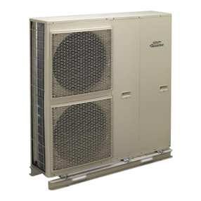
1) Evaporator
2) Fan
3) Expansion valve
4) Switch box
5) Connection for refrigerant line
1
2
3
4
5
www.gdts.one DOK4x HCIAO WxDEN · FD 9912 7
Air-to-water heat pump 6 kW with cooling English
4 Transport
4.1 Outdoor unit
A pallet should be used to transport the heat pump to its final
installation location. The outdoor unit can be transported with a
lift truck, hand truck or similar.
Once the side sections have been removed, the outdoor unit
can be lifted by the cover. For this, loosen the two screws at the
top, tilt the metal plate to the side and remove at the top (see
step 1-3)
4.2 Indoor unit
A lift truck is suited for transporting the unit on a level surface.
Carrying straps may be used if the heat pump needs to be
transported on an uneven surface or carried up or down stairs.
These straps can be passed directly underneath the pallet.
To lift from the pallet, the indoor unit can be tilted back by up to
45° and lifted by the handles on the back at the top. Tilting over
45° is not permitted without removing the refrigeration circuit
beforehand.
To remove the refrigeration circuit, remove the side plate at the
bottom right.
The casing panels must be dismantled in the order outlined be-
low.
The bottom side panel must be removed first.
For this, loosen the screws on the bottom side section, turn out
the panel slightly and pull it out to the front (see step 1-3).
Secondly, remove the top side panel.
To do this, loosen the screws, fold out the panel slightly and re-
move the facade panel at the top (see step 4-6).
The front panel can then be removed.
For this, loosen the 4 screws on the frame at the side. Push the
panel approx. 10 mm to the right, then push it forwards slightly
and remove at the top (see step 7-9). Disconnect the connec-
tion cables to the display on the universal hardware interface.
1.
2.
3.
1.
45°
max.
Tilting dimension 2190
2.
3.
1.
1.
4.
4.
5.
6.
7.
7.
7.
7.
8.
9.
8 DOK4x HCIAO WxDEN · FD 9912 www.gdts.one
English Air-to-water heat pump 6 kW with cooling
4.3 Removing the refrigeration
circuit
To make transport easier, the refrigeration circuit can be dis-
mantled and transported separately. Removing it enables the
indoor unit to be transported horizontally.
The following connections must be disconnected:
1) Disconnect the water circuit connection
2) Disconnect the plug connections on the refrigeration cir-
cuit switch box
3) Loosen the mounting screws
4) Pull the refrigeration circuit out at the side and transport it
to the intended location
!!
ATTENTION!
In installed and dismantled state, the refrigeration circuit may
only be tilted by a maximum of 45° (in each direction).
After the final positioning at the installation location, remove
the transport fastening on the sprung floor of the compressor
on both sides.
!!
ATTENTION!
Before commissioning, the transport fastening must be re-
moved.
1. (2x)
3. (2x)
4.
2. (2x)