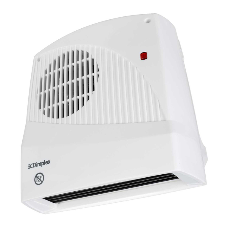
Dimplex EF12 Series User manual
Other Dimplex Heater manuals

Dimplex
Dimplex FX 20E IPX4 User manual

Dimplex
Dimplex SCH5 User manual
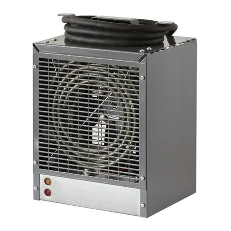
Dimplex
Dimplex EMC4240 User manual
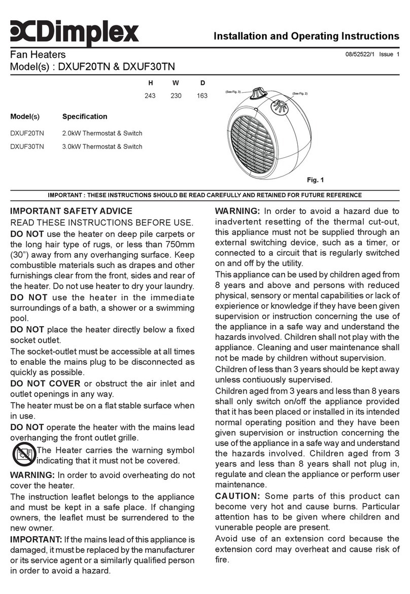
Dimplex
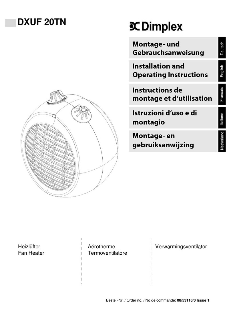
Dimplex DXUF20TN User manual
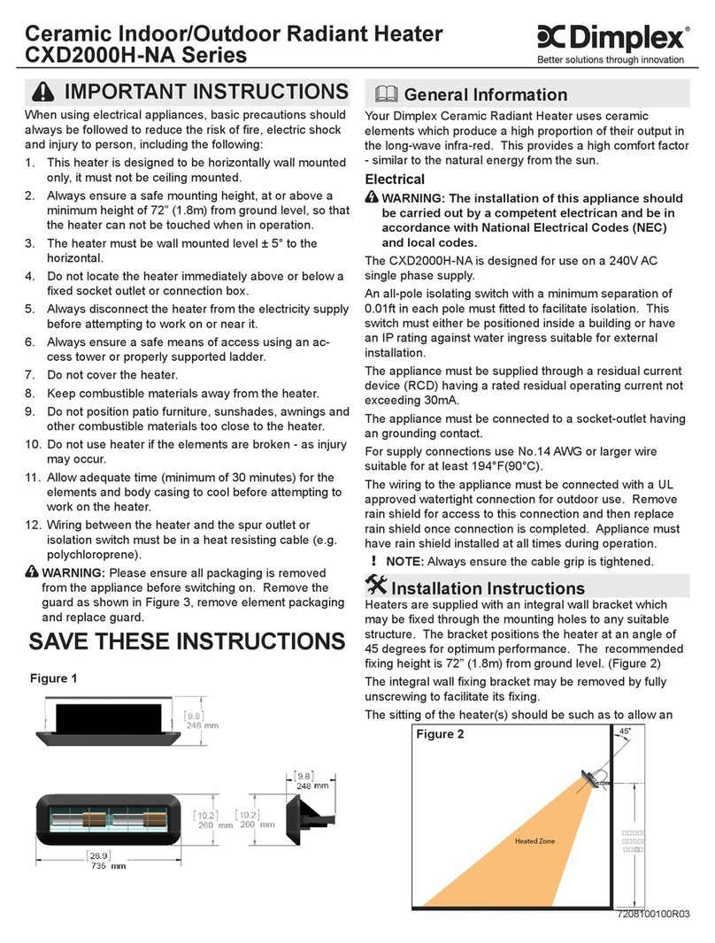
Dimplex
Dimplex CXD2000H-NA Series User manual

Dimplex
Dimplex NELSON DELUXE NLS20RC User manual
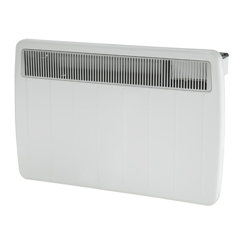
Dimplex
Dimplex PLX075NN User manual
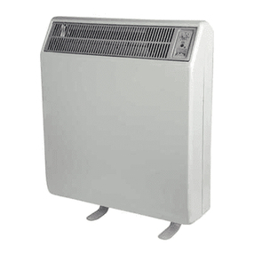
Dimplex
Dimplex CXLS12N User manual
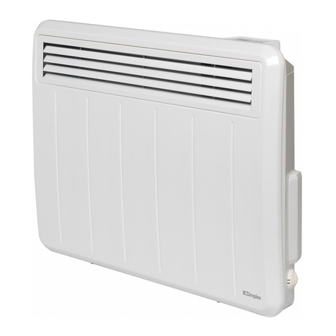
Dimplex
Dimplex PLXE Series User manual
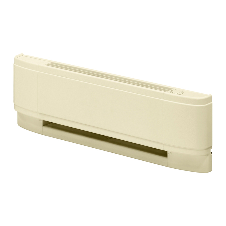
Dimplex
Dimplex LC Series User manual
Dimplex
Dimplex LS 200 User manual
Dimplex
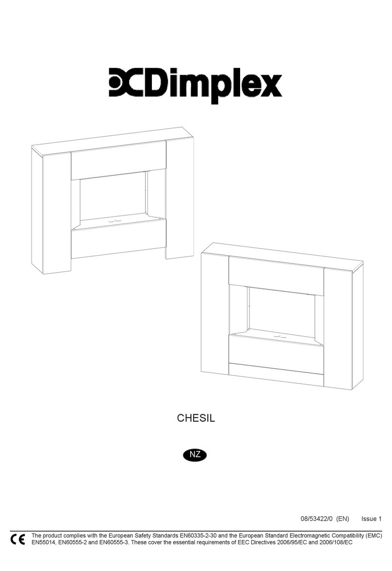
Dimplex CHESIL CLS20 User manual
Dimplex
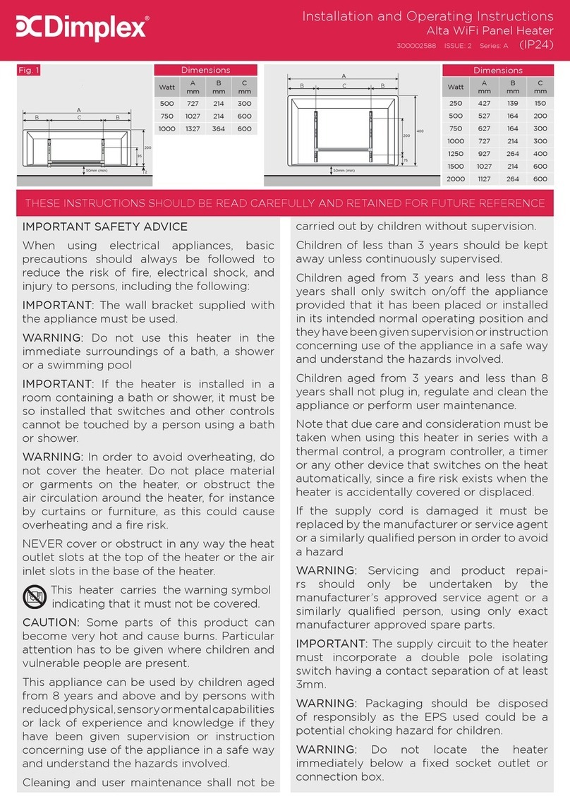
Dimplex DTD2R05 User manual
Dimplex
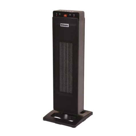
Dimplex DHCER24E User manual
Dimplex
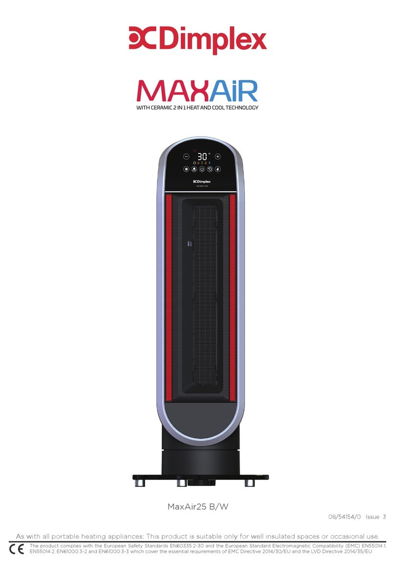
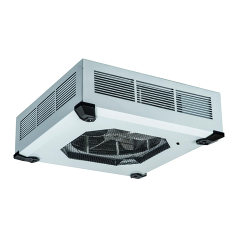
Dimplex MaxAir25 B User manual
Dimplex
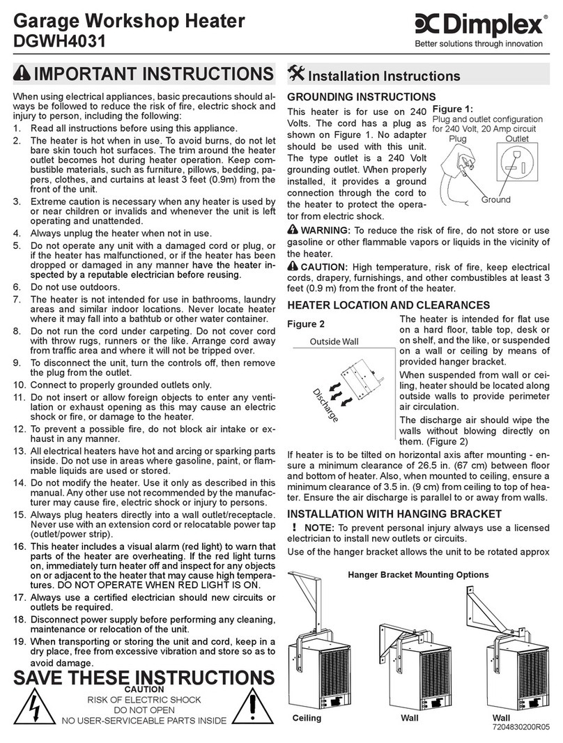
Dimplex RCH5031CXW User manual
Dimplex
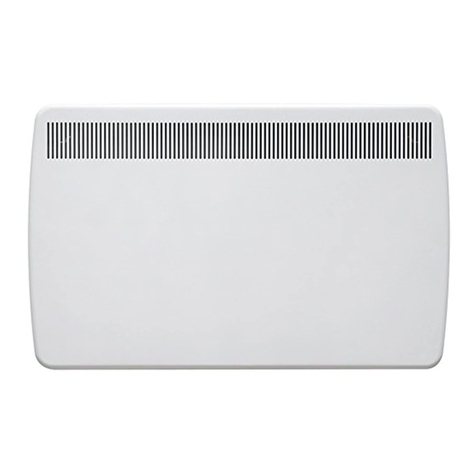
Dimplex DGWH4031 User manual
Dimplex
Dimplex DTX Series Installation instructions manual

Dimplex
Dimplex DTD User manual
Dimplex
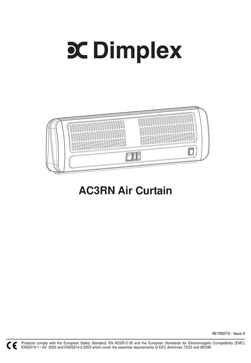
Dimplex AC3RN User manual
Popular Heater manuals by other brands

oventrop
oventrop Regucor Series quick start guide

Blaze King
Blaze King CLARITY CL2118.IPI.1 Operation & installation manual

ELMEKO
ELMEKO ML 150 Installation and operating manual

BN Thermic
BN Thermic 830T instructions

KING
KING K Series Installation, operation & maintenance instructions

Empire Comfort Systems
Empire Comfort Systems RH-50-5 Installation instructions and owner's manual

Well Straler
Well Straler RC-16B user guide

EUROM
EUROM 333299 instruction manual

Heylo
Heylo K 170 operating instructions

Eterna
Eterna TR70W installation instructions

Clarke
Clarke GRH15 Operation & maintenance instructions

Empire Heating Systems
Empire Heating Systems WCC65 Installation and owner's instructions
