DINA DNSR-2R User guide
DNSR-2R
Original Betriebsanleitung
Original Instruction Manual
wir sind sicherheit.
we are safety

DNSR-2R Original Betriebsanleitung
Original Instruction Manual
DNSR-2R Stand 15.08.2016 Seite 2 von 8 Date 2016-08-15 Page 2 von 8
Inhaltsver eichnis
Seite
Contents
Page
Eigenschaften
2
Features
2
estimmungsgemäße
Verwendung
2
Intended purpose
2
Sicherheitsbestimmungen
3
Safety regulations
3
Wichtiger Hinweis und Validierung
3
Important notes and validation
3
Verwendung 33SR02 / 33SR03
4
Usage
33SR02 / 33SR03
4
Funktionsart 1
4
Functional mode 1
4
Funktionsart 2
4
Functional mode 2
4
Funktionsart 3
4
Functional mode 3
4
Funktionsart 4
5
Functional mode 4
5
Anzeige und Anmerkung
5
Display and remark
5
Funktion: ID
-
No.: 33SR10, 33SR11, 33SR12
5
Function
: ID
-
No.: 33SR10, 33SR11, 33SR12
5
Technische Daten
6
Technical data
7
Kontaktlebensdauer
7
Contact life
7
Abmessungen
7
Dimension
7
Zertifikat
8
Certificate
8
Eigenschaften
Featur
e
s
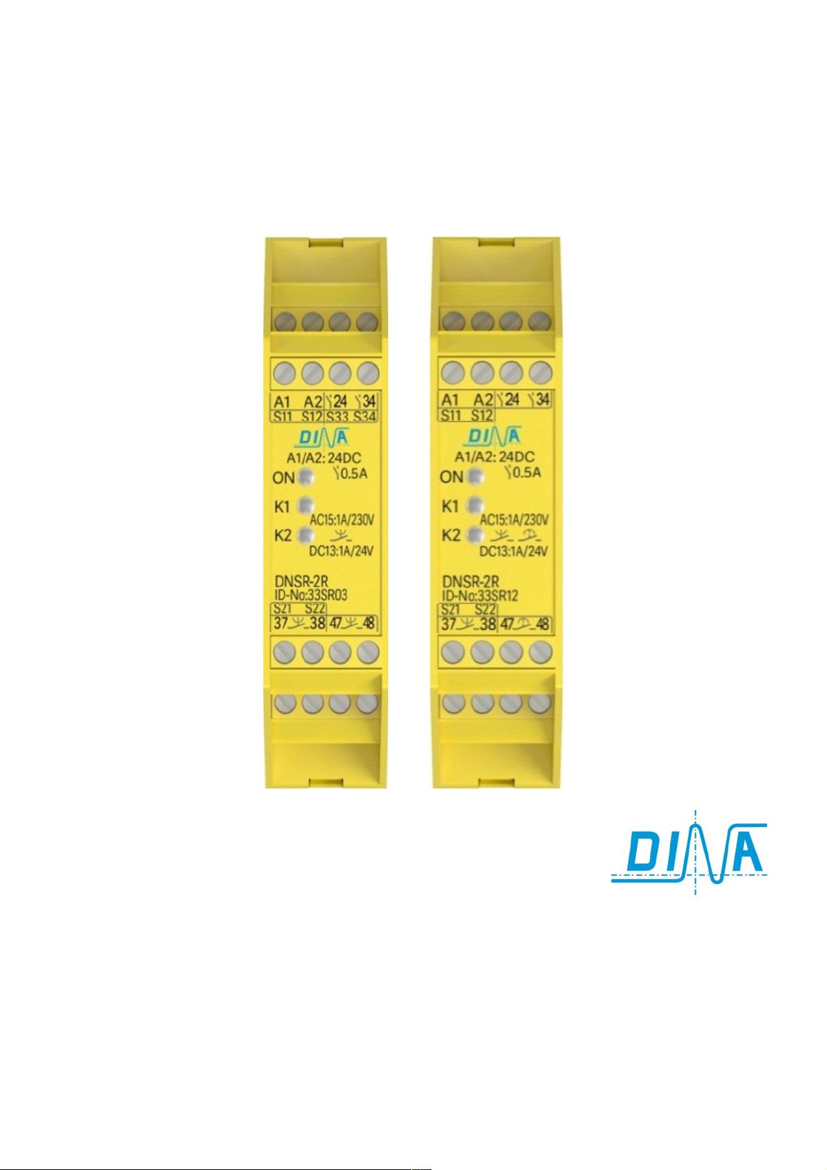
3 unverzögerte Kontakte
1 Kontakt rückfallverzögert
etriebsart 1/ PLd
◄33SR02
3 undelayed contacts
1 off delayed contact
Functional mode 1/ PLd
2 unverzögerte Kontakte
2 Kontakte rückfallverzögert
etriebsart 3/ PLd
33SR03►
2 undelayed contacts
2 off delayed contact
Function mode 3/ PLd
2 Diagnose Kontakte
1 Kontakt rückfallverzögert PLc
1 Kontakt anzugverzögert PLc
Funktionsart 4A
◄33SR10/ 33SR12▲
2 diagnostics contacts
1 contact off delayed PLc
1 contact on delayed PLc
Function mode 4A
2 Diagnose Kontakt
2 Kontakte rückfallverzögert PLc
Funktionsart 4A
33SR11►
2 undelayed contacts
2 off delayed contact PLc
Function mode 4A
Bestimmungsgemäße Verwendung
Prüfgrundlage:
Intended purpose
Testing based on:
•EN 55011: 2009+A1: 2010, EN 61326-1: 2006-05 (Klasse ):
Elektrische Mess-, Steuer-, Regel- und Laborgeräte –
EMV-Anforderungen
•DIN EN 60947-5-1: Niederspannungsschaltgeräte-Teil 5-1:
Steuergeräte und Schaltelemente; Elektromechanische
Steuergeräte
•ISO EN 13849-1: Sicherheit von Maschinen – Sicherheits-
bezogene Teile von Steuerungen Teil 1,
Funktionsart 1, 2 und 3: Kategorie 3, PLd,
Funktionsart 4, 4A: Kategorie 1, PLc
•DIN EN ISO 13849-2: Sicherheitsbezogene Teile von
Steuerungen Teil 2: Validierung
•GS-ET-20: Zusatzanforderungen für die Prüfung und
Zertifizierung von Sicherheitsschaltgeräten"
•EN 55011: 2009+A1: 2010, EN 61326-1: 2006-05 (class ):
electrical measuring, control, rule and laboratorial equipment-
EMC-requirements
•DIN EN 60947-5-1: Low-voltage switch gear and control gear;
part 5.1: control circuit devises and switching elements -
electromechanical control circuit devices
•DIN EN ISO 13849-1: Safety-related parts of control systems;
Part 1: General principles for design
functional mode 1, 2 and 3: category 3, PLd,
function mode 4 and 4A: category 1, PLc
•DIN EN ISO 13849-2: Safety-related parts of control systems;
Part 2: Validation
•GS-ET-20: supplementary requirements for testing and
certification of safety switchgear
evollmächtigter für die Zusammenstellung der technischen
Unterlagen: Dirar Najib, Geschäftsführer
Esslinger Str. 84, 72649 Wolfschlugen
Wolfschlugen, 12.08.2016
Authorized person for the compilation of the technical
documentations: Dirar Najib, CEO
Esslinger Str. 84, D 72649 Wolfschlugen
Wolfschlugen, 2016-08-12
Zertifikat und EU Konformitätserklärung
Siehe www.dina.de
Certificate and declaration of conformity
See www.dina.de

DNSR-2R Original Betriebsanleitung
Original Instruction Manual
DNSR-2R Stand 15.08.2016 Seite 3 von 8 Date 2016-08-15 Page 3 von 8
Prüf- und Zertifizierungsstelle
Elektrotechnik
Europäisch notifizierte Stelle
Kenn-Nr.: 0340
ET 16095 vom 04.07.2016
ET 16095 from 2016-07-04
File E227037
Gerät ist nicht zugelassen
als Sicherheitsgerät nach
UL 508
Device is not evaluated
as safety device under
UL 508
Zertifi ierungsdaten
Certificate data
Funktionsart
Function
mode
1, 2,
3
MTTFd
98 Jahre
Years
SFF
≥ 93%
CCF
75 Punkte
points
PFHd
4,3 x 10
-
8
PLd
Funktionsart
Function
mode
4
, 4A
MTTFd
98 Jahre
Years
0%
PLc
Sicherheitsbestimmungen
•Das Gerät darf nur von einer Elektrofachkraft oder
unterwiesenen Personen installiert und in etrieb genommen
werden, die mit dieser etriebsanleitung und den geltenden
Vorschriften über Arbeitssicherheit und Unfallverhütung
vertraut sind.
•eachten Sie die VDE- sowie die örtlichen Vorschriften,
insbesondere hinsichtlich der Schutzmaßnahmen.
•Halten Sie beim Transport, der Lagerung und im etrieb die
edingungen nach EN 60068-2-6, 04/95 ein.
•Werden die Vorschriften nicht beachtet, kann Tod, schwere
Körperverletzungen oder hoher Sachschaden die Folge sein.
•ei Not-Halt Anwendungen muss der automatische
Wiederanlauf der Maschine verhindert werden.
•Durch eigenmächtige Umbauten erlischt jegliche
Gewährleistung. Es können dadurch Gefahren entstehen, die
zu schweren Verletzungen oder sogar zum Tod führen.
•Montieren Sie das Gerät in einen Schaltschrank; Staub und
Feuchtigkeit können sonst zu eeinträchtigungen der
Funktionen führen. Der Einbau in einem Schaltschrank ist
zwingend.
•Sorgen Sie an allen Ausgangskontakten bei kapazitiven und
induktiven Lasten für eine ausreichende Schutzbeschaltung.
•Das Gerät ist unter erücksichtigung der nach DIN EN 50274,
VDE 0660-514 geforderten Abstände einzubauen.
•Während des etriebes stehen Schaltgeräte unter gefährlicher
Spannung. Schutzabdeckungen dürfen nicht entfernt werden.
•Wechseln Sie das Gerät aus nach dem ersten Fehlerfall und
entsorgen Sie es sachgerecht nach Ablauf der Lebensdauer!
•
ewahren Sie
diese Produktinformation auf!
Safety regulations
•The unit may only be installed and operated by those who
are qualified electrical engineers or have received
sufficient training and are familiar with both these
instructions and the current regulations for safety at work
and accident prevention.
•Follow VDE, EN as well as local regulations especially as
regards preventative measures!
•Transport, storage and operating conditions should all
conform to EN 60068-2-1, 2-2.
•Ignoring the safety regulations can lead to death, serious
injury or cause considerable damage!
•In emergency stop applications must ensure that the
machine cannot start up again automatically!
•Any guarantee is void following unauthorised
modifications. This can lead to death, serious injury or
cause considerable damage!
•The unit should be mounted in a cabinet with a protection
class of IP54. Otherwise dampness and dust could lead to
functional impairment. The installation in a control cabinet
is imperative.
•Adequate fuse protection must be provided on all output
contacts especially with capacitive and inductive loads.
•The unit must be installed following the specification of
DIN EN 50274, VDE 0660-514 regarding the required
distances.
•During operation, parts of the electronic switchgear carry
high voltage. The protective covers must not be removed.
•The device must be replaced after the first malfunction
and
properly disposed after reaches the end of it service life.
•
Keep the operating instructions!
Wichtiger Hinweis und Validierung Important notes and validation
Das hier beschriebene Produkt wurde entwickelt, um als Teil
eines Gesamtsystems sicherheitsgerichtete Funktionen zu
übernehmen. Das Gesamtsystem wird durch Sensoren,
Auswerte- und Meldeeinheiten sowie Konzepte für sichere
Abschaltungen gebildet. Es liegt im Verantwortungsbereich des
Herstellers einer Anlage oder Maschine die korrekte
Gesamtfunktion sicherzustellen. Der Hersteller der
Anlage/Maschine ist verpflichtet, die Wirksamkeit des
implementierten Sicherheitskonzepts innerhalb des
Gesamtsystems zu prüfen und zu dokumentieren. Dieser
Nachweis ist nach jeglicher Modifikation am
Sicherheitskonzept bzw. Sicherheitsparametern erneut zu
erbringen. DINA Elektronik GmbH ist nicht in der Lage, alle
Eigenschaften eines Gesamtsystems, das nicht durch DINA
konzipiert wurde, zu garantieren. DINA Elektronik GmbH
übernimmt auch keine Haftung für Empfehlungen, die durch die
nachfolgende eschreibung gegeben bzw. impliziert werden.
Auf Grund der nachfolgenden eschreibung können keine
neuen, über die allgemeinen Lieferbedingungen der DINA
Elektronik GmbH hinausgehenden Garantie-, Gewährleistungs-
oder Haftungsansprüche abgeleitet werden.
This installation instruction includes the necessary
information needed for correct installation.
More detailed information is available on the attached CD.
The described product has been developed as a part of a
safety system. The system includes sensors, evaluation
units, control units and a concept for safe switch-off.
The manufacturer is in charge of ensuring the correct
functionality of the entire system.
The manufacturer is in charge of checking and proving the
effectiveness of the safety concept.
Any modification at the safety parameters or the safety
concept itself requires re-proving the effectiveness of the
safety concept.
DINA Elektronik GmbH cannot guarantee properties of
systems that not have been established in their own
responsibility.
DINA Elektronik GmbH also does not accept liability for any
recommendations derived from the following description.
Claims that go beyond the rights cited in the warranty are
excluded.
R
1ZD7
US LISTED
IND.CONT.EQ

DNSR-2R Original Betriebsanleitung
Original Instruction Manual
DNSR-2R Stand 15.08.2016 Seite 4 von 8 Date 2016-08-15 Page 4 von 8
Verwendung
33SR02 / 33SR03
Usage
33SR02 / 33SR03
•
Das Not-Halt Relais DNSR-2R ist vorgesehen zur
Stilllegung von earbeitungsmaschinen beim
Auftreten von Gefahren. Die Kontakte sind als NO
ausgeführt.
•Die Kontakte 14, 24 und 24, 34 sind potentialgebunden
an 24V DC, andere sind potenzialfrei.
•Sie sind so zu verwenden, dass die vorgesehene Not-
Halt Funktion ausgeführt wird.
•DNSR-2R kann in Sicherheitskreisen nach VDE 0113 Teil
1 eingesetzt werden.
•Abhängig von der DNSR-2R Version ist maximal
Kategorie 3 / PLd nach DIN EN ISO 13849-1 zu
erreichen.
•DNSR-2R ist in einem 22.5mm Kunststoffgehäuse zum
Einbau auf einer 35mm Norm Hutschiene vorgesehen.
•
Ein Anschlussplan ist s
eitlich auf dem Gerät.
•
The emergency stop relay DNSR-2R is designated
for the shutdown of machining centre in the event
of danger. All contacts are NO.
•The contacts 14, 24 and 24, 34 are potential closed
to 24V DC the others are potential free.
•They are used to cause the designated emergency
stop function.
•DNSR-2R can be used in safety circuits according to
VDE 0113 part 1.
•Depending of the version of DNSR-2R maximal
category 3 / PLd according to DIN EN ISO 13849-1
can be reached.
•DNSR-2R is mounted in a 22.5
mm plastic housing to
be installed on a 35mm standard rail.
•A connection plan is on the side of the unit.
Funktionsart 1
•Diese Funktion ist ein einkanaliger Not-Halt Kreis mit
einem Start (S12) und Quitt Kreis (S34).
•eide Kreise werden über geräteinterne Spannung 15V
an S11 und S33 angesteuert.
•Die 15V werden über die Taster für Not-Halt und Quitt
zu S12 und S34 geschaltet.
•Nach dem Abschalten von S34 schließen alle
Kontakte.
•ei Unterbrechung der 15V von S12 schalten die
Kontakte 24 und 34 sowie der Kontakt 13-14 sofort ab.
Der Kontakt 47-48 ist rückfallverzögert.
•Die Rückfallzeit ist intern eingestellt.
•
Ein
-
und
Ausgänge werden auf Plausibilität geprüft.
Functional mode 1
•This function is one channel emergency stop circuit
with a start (S12) and quit circuit (S34).
•oth circuits are controlled with the unit internal
voltage 15V at S11 and S33.
•The 15V is switched on to S12 and S34 with the
button of the emergency stop and quit.
•After the switching off of S34 the contacts are
immediately closed.
•After the switching off of S12 the contacts 24, 34
and 13-14 open immediately. The contact 47-48 is off
delayed.
•The time delay is adjusted internal.
•
The
In
-
and outputs are checked for plausibility.
Funktionsart 2
•2 Start (S12, S22) und 2 Quitt Kreise (S34, S44) sind
verfügbar.
•Die Kreise werden über geräteinterne Spannung 15V an
S11 und S33 bzw. 12V an S21 und S43 angesteuert.
•Die 15V werden zu S12 und S34 die 12V zu S22 und S44
über den Not-Halt und Quitt Taster geführt.
•Nach dem Abschalten von S34 und S44 schließen
die Kontakte sofort.
•Wird S12 oder S12 und S22 vom Potential getrennt,
schalten die Kontakte 14 und 24 sofort ab.
•37-38 und 47-48 sind rückfallverzögert ab.
•Die Rückfallzeit wird intern eingestellt.
•
Ein
-
und Ausgänge werden
auf Plausibilität geprüft.
Functional mode 2
•Two start (S12, S22) and 2 quit circuits (S34, S44) are
available.
•The circuits are controlled with the unit internal
voltage 15V at S11 and S33, 12V at S21 and S43.
•The 15V is switched on to S12 and S34 the 12V to S22
and S44 via the emergency stop and quit button.
•After the switching off of S34 and S44 the
contacts are immediately closed.
•After the switching off of S12 or S12 and S22 the
contacts 14 and 24 open immediately.
•The contacts 37-38 and 47-48 are off delayed.
•The time is adjusted internal.
•
The In
-
and outputs are checked for plausibility.
Funktionsart 3
•Zwei Start (S12, S22) und 1 Quitt Kreis (S34) sind
verfügbar.
•Die Kreise werden über geräteinterne Spannung 15V an
S11 und S33 bzw. 12V an S21 angesteuert.
•Die 15V werden zu S12 und S34 die 12V zu S22 über den
Not-Halt und Quitt Taster geschaltet.
•Nach dem Abschalten von S34 schließen die
Kontakte sofort.
•Wird S12 oder S12 und S22 vom Potential getrennt,
schalten die Kontakte 14 und 24 sofort ab.
•Die Kontakte 37-38, 47-48 sind rückfallverzögert.
•Die Rückfallzeit wird intern eingestellt.
•
Ein
-
und Ausgänge werden auf Plausibilität geprüft.
Functional mode 3
•Two start circuits (S12, S22) and one quit (S34) are
available.
•The circuits are controlled with the unit internal
voltage 15V at S11 and S33 respectively 12V at S33.
• The 15V is switched on to S12 and S34 the 12V to
S22 with the button of the emergency stop and quit.
•After the switching off of S34 the contacts are
immediately closed.
•After the switching off of S12 or S12 and S22 the
contacts 14 and 24 open immediately.
•The contacts 37-38 and 47-48 are off delayed.
•The time is adjusted internal.
•
The In
-
and outputs are checked for plausibility
.
Die
Die Die
Die Funktionsart
FunktionsartFunktionsart
Funktionsarten
enen
en
1, 2 und 3
1, 2 und 31, 2 und 3
1, 2 und 3
erreich
erreicherreich
erreichen
enen
en
die
die die
die
Sicherheitskategorie
Sicherheitskategorie Sicherheitskategorie
Sicherheitskategorie
3
33
3
, PL
, PL, PL
, PL
d
dd
d
nach DIN EN ISO 13849
nach DIN EN ISO 13849nach DIN EN ISO 13849
nach DIN EN ISO 13849
1.
1.1.
1.
Th
ThTh
The
ee
e
function
functionfunction
function
mode
modemode
modes
ss
s
enable
enableenable
enable
the
the the
the saf
safsaf
safety
ety ety
ety category 1,
category 1, category 1,
category 1,
PLc according to DIN EN ISO 138
PLc according to DIN EN ISO 138PLc according to DIN EN ISO 138
PLc according to DIN EN ISO 138
49
4949
49
1.
1.1.
1.

DNSR-2R Original Betriebsanleitung
Original Instruction Manual
DNSR-2R Stand 15.08.2016 Seite 5 von 8 Date 2016-08-15 Page 5 von 8
Funktionsart 4
•Diese Funktion hat 2 getrennte Steuerkreise jeweils
mit einem Start S12 und Quitt S34 kreis bzw. S22,
S44.
•Die Kreise werden über geräteinterne Spannung 15V
an S11 und S33 bzw. 12V an S21 und S43 angesteuert.
•Die 15V werden zu S12 und S34 die 12V zu S22 und
S44 über den Not-Halt und Quitt Taster geschaltet.
•Nach dem Abschalten von S34 schließen die
Kontakte 14 und 37-38 sofort. 14 öffnet sofort und 37-
38 rückfallverzögert, wenn S12 potentialfrei wird.
•Nach dem Abschalten von S44 schließen die
Kontakte 24 und 47-48. 24 öffnet sofort und 47-48
rückfallverzögert, wenn S22 potentialfrei wird.
•Die Rückfallzeit wird intern eingestellt.
•Ein- und Ausgänge werden auf Plausibilität geprüft.
•Diese Funktionsart erreicht Sicherheitskategorie 1,
PL
c
nach DIN EN ISO 13849
-
1.
Functional mode 4
•This function has 2 separate control circuits each with
one start S12, S22 and one quit S34, S44 circuit.
•The circuits are controlled with internal voltage 15V at
S11 and S33, 12V at S21 and S43.
•The 15V is switched on to S12 and S34, 12V to S22 and
S44 via the emergency stop and quit button.
•After the switching off of S34 the contacts 14 and
37-38 are immediately closed. After the switching off
of S12 the contact 14 open immediately. The contact
37-38 is off delayed. After the switching off of S44
the contacts 24 and 47-48 are immediately closed.
•After the switching off of S22 the contact 24 open
immediately. The contact 47-48 will switch off delayed.
• The time is adjusted internal.
•The In- and outputs are checked for plausibility
•This function mode enables the safety category 1, PLc
according to DIN EN ISO 138
49
-
1.
etriebsart 1 etriebsart 2 etriebsart 3 etriebsart 4
Functional mode 1 Functional mode 2 Functional mode 3 Functional mode 4
S12
S34
24+34+13-14
47-48 t
S12+S22
S34+S44
14+24
37-38+47-48 t
S12+S22
S34
14+24
37-38+47-48 t
S12 / S22
S34 / S44
14 / 24
37-38 / 47-48 t
ID-No:33SR02
13
5 6 7 8
S11
15V
S12
1314 4748
14 15 16
S33 S34
15V
3 4
24 34A1 A2
1 2
24VDC
0V
ID-No:33SR03
13
5 6 7 8
S11
15V
S12
3 4
14 24A1 A2
3738 4748
14 15 16
S33 S34
15V
9 10 1211
S21
S22
12V
1 2
24VDC
0V
An eige und Anmerkung
•etriebsspannung eingeschaltet: LED ON leuchtet.
•Nur Start Kreis 1 ist unterbrochen: LED K1 blinkt
•Nur Start Kreis 2 ist unterbrochen: LED K2 blinkt
•Für die Quittierung müssen beide Start Kreise
unterbrochen werden.
•eide Kreise müssen innerhalb 1s aktiv oder offen sein
•eide LED K1, K2 leuchten bei richtiger Ansteuerung
und geschlossenen Kontakten.
Display and remark
•Power supply ON: LED ON illuminates
•Only Start circuit 1 is switching off: LED K1 is flashing
•Only Start circuit 2 is switching off: LED K2 is flashing
•To quit the emergency stop circuit both start circuits
have to be switched off.
•oth circuits have to be during 1s active or open.
•oth LED illuminate with proper input signal and
closed contacts.
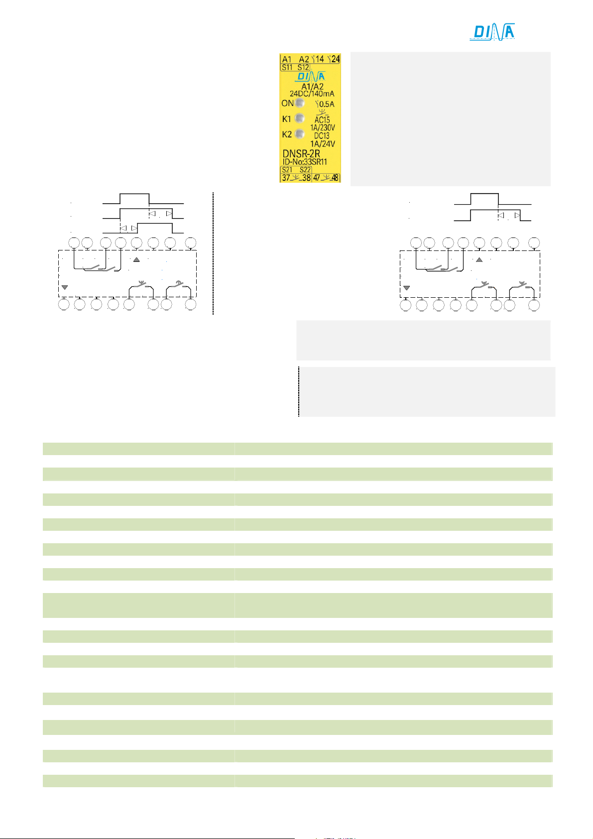
Funktion: ID-No.: 33SR10, 33SR11, 33SR12
•Diese etriebsart hat 2 getrennte Steuerkreise.
•Jeder Kreis verfügt über einen Startkreis S12 bzw. S22.
•Die Kreise werden über geräteinterne Spannung 15V
an S11 bzw. 12V an S21 angesteuert.
•Die Potentiale werden über die Steuertasten zu S12
und S22 geschaltet.
Function: ID-No.: 33SR10, 33SR11, 33SR12
•This function has 2 separate control circuits.
•Each with one start circuit S12 respectively S22.
•The circuits are controlled with the unit internal
voltage 15V at S11 respectively 12V at S21.
•The 15V is switched on to S12, the 12V to S22 with the
control button.
ID-No. 33SR10:
37/38 und 45/48 (1.5s) Verzögerungszeit
ID-No. 33SR12:
•37/28: 1.5s, 45/48: 50s Verzögerungszeit.
intern eingestellt.
•Wird S12 gegen 15V geschaltet schließt
der Kontakt 37-38.
•37-38 öffnet rückfallverzögert,
wenn S12 potentialfrei wird.
•Wird S22 gegen 12V geschaltet schließt
der Kontakt 45-48 anzugsverzögert.
•45-48 öffnet sofort, wenn S22
potentialfrei wird.
ID-No. 33SR10:
37/38 and 45/48 (1.5s) delay time
ID-No. 33SR12:
•37/28 (1.5s), 45/48 (50s) delay time.
The delay time is adjusted internal.
•After the switching on of S12 to 15V
the contact 37-38 closed.
•After the switching off of S12 of 15V
the contact 37-38 opens delayed.
•After the switching on of S22 to 12V
the contact 45-48 closes ON delayed.
•After the switching off of S12 the
contact
45
-
48
open
s
directly
.
DNSR-2R Original Betriebsanleitung
Original Instruction Manual
DNSR-2R Stand 15.08.2016 Seite 6 von 8 Date 2016-08-15 Page 6 von 8
ID-No. 33SR11:
•37/38 und 47/48 (15s) Rückfallzeit.
Die Verzögerungszeit wird intern eingestellt.
•Wird S12 gegen 15V geschaltet schließen die
Kontakt 37-38 sofort.
•37-38 öffnet rückfallverzögert, wenn S12
potentialfrei wird.
•Wird S22 gegen 12V geschaltet schließt der
Kontakt47-48 sofort.
•47-48 öffnet rückfallverzögert, wenn S22
potentialfrei wird.
ID-No. 33SR11:
•37/38 and 47/48 (15s) off delayed time.
The off delay time is adjusted internal.
•After the switching on of S12 to 15V the
contact 37-38 closes directly.
•After the switching off of S12 of 15V the
contact 37-38 opens off delayed.
•After the switching on S22 to 12V the
contact 47-48 closes directly.
•After the switching off S12 of 12V the
contacts
47
-
48 opens off delayed.
S12 / S22
37-38 t
t45-48
S12 / S22
37-38 / 47-48 t
ID-No:
13
5 6 7 8
S11
15V
S12
1 2 3 4
14 24A1 A2
37 38 45 48
14 15 16
9 10 1211
S21
S22
12V
24V
0V
DC
PLc
33SR10
33SR12
ID-No:33SR11
13
5 6 7 8
S11
15V
S12
1 2 3 4
14 24A1 A2
37 38 47 48
14 15 16
9 10 1211
S21
S22
12V
24V
0V
DC
PLc
Die Ausgangskontakte 14 und 24 sind Diagnose
Kontakte für interne Fehler bzw. externe Ansteuerung
mit einem ungeeignetem Potential.
The output contact 14 and 24 are diagnostics contacts
for internal failure respectively an external control with
inappropriate potential.
LED
LEDLED
LED
Anzeige:
Anzeige: Anzeige:
Anzeige:
ON: etriebsspannung.
K1: Kontakt 14 und 37-38
K2: Kontakt 24 und 45-48 bzw. 24 und 47-48
LED Display
LED DisplayLED Display
LED Display
ON: Power supply
K1: contact 14 and 37-38
K2: contact 24 and 45-48 respectively 24 and 47-48
Technische Daten
Allgemeine technische Daten
etriebsspannung 24VDC +/- 10%
Stromaufnahme ca. 40mA in Ruhestellung, ca. 70mA in Wirkstellung
Sicherung Intern PTC Sicherung 200mA
etriebstemperatur -10°C bis +60°C
Lagertemperatur
-40°C bis +80°C
Rüttelfestigkeit Sinus 10–50 Hz, 0,35mm, 10 Zyklen, 1 Oktave /min
Maximaler Anschlussquerschnitt 1,5mm² mit Aderendhülse
Anzugsmoment bei Schraubklemme 05-06 Nm
Anschlussdraht 60/75°C Kupfer
Gehäusematerial Polyamid PA unverstärkt
Schutzart Für Schaltschrankeinbau ≥ IP 54, Klemmen IP20
emessungsisolationsspannung 250V AC, nicht für die Kontakte 14, 24
Stoßspannungsfestigkeit
Verschmutzungsgrad 2 Umgebung 4KV, nicht für die Kontakte 14, 24 und 34
Technische Daten der Eingänge
S12, S34 15V ± 0.5V intern an S11, S33 Prüfung gegen fremde Spannung
S22, S44 12V ± 0.5V intern an S21, S43 Prüfung gegen fremde Spannung
Technische Daten der Kontaktausgänge
Potentialgebundene Kontakte 14, 24 und
34 (NO) minimal: 3mA, maximal: 0,5A aus Geräte etriebsspannung
Potentialfreie Kontakte Minimal: 10mA, maximal: 6A, Kontaktabsicherung 5A träge
Schaltvermögen nach IEC/EN 60947-4-1 AC1: 230V / 6A, DC1: 24V / 6A, 10
5
Schaltspiele
Nach IEC/EN 60947-5-1 AC15: 230V/ 3A, 7x10
4
Schaltspiele, DC13: 24V/ 4A, 4x10
4
Schaltspiele
Mechanische Lebensdauer > 20 x 10
6
Schaltspiele
Kontaktwerkstoff AgNi10
Maximale Schaltspiele 360 Zyklen/h bei max. Schaltstrom AC15+ DC13
Ansprechzeit, Rückfallzeit Typisch 10ms, Typisch 6ms

DNSR-2R Original Betriebsanleitung
Original Instruction Manual
DNSR-2R Stand 15.08.2016 Seite 7 von 8 Date 2016-08-15 Page 7 von 8
Technical data General technical data
Power supply 24VDC +/- 10%
Current drain ca. 40mA relay off, ca. 70mA relay on
Fuse Internal PTC fuse 200mA
Operating temperature -10°C to +60°C /
Storage temperature 40°C to +80°C
Vibration resistance Sin 10 – 50 Hz, 0,35mm, 10 cycles, 1 Octave /min
Maximal cable cross section 1,5 mm² with wire end sleeve
Tightening torque with screw terminal 0,5-06 Nm
Connection wire 60/75°C copper
Housing material Polyamide PA non-reinforced
Protection class Installation in a closed cabinet with ≥ IP54, terminals: IP20
Rated Isolation voltage 250V AC not for the contacts 14, 24, 34
Impulse withstand voltage
pollution degree 2 environment
4KV, not for the contacts 14, 24, 34
Technical data of inputs
S12, S34 15V ± 0.5V, internal at S11, S33 test against other voltage
S22, S44 12V ± 0.5V, internal at S21, S43 test against other voltage
Technical data of the contact outputs
Contacts closed to power supply, 14, 24 and 34
(NO) Minimal: 3mA, maximal: 0,5A from the power supply of the unit
Potential free contacts Minimal: 10mA, maximal: 6A, contact fuse 5A slow
Switch current according to IEC/EN 60947-4-1 AC1: 230V / 6A, DC1: 24V / 6A, 10
5
cycles
According to IEC/EN 60947-5-1 AC15: 230V/ 3A, 7x10
4
cycles, DC13: 24V/ 4A, 4x10
4
cycles
Mechanical life > 20 x 10
6
cycles
Contact material AgNi10
Maximal cycles 360 cycles/h with maximal switching current AC15+ DC13
Reaction time / Drop out time Typical 10ms / Typical 6ms
Kontaktlebensdauer
Contact life
Abmessungen
Dimension
10
50
100
500
1000
5000
10.000
Schaltspiele x 1000 / Cycles x 1000
0.1
0.5
1.0
5.0
10.0
2.0
3.0
4.0
6.0
Schaltstrom (A) / Switching current (A)
DC13:
24V
AC15:
230V
AC1.
230V
DC1:
24V
99
114.5
22,5

DNSR-2R Original Betriebsanleitung
Original Instruction Manual
DNSR-2R Stand 15.08.2016 Seite 8 von 8 Date 2016-08-15 Page 8 von 8
Wir sind Sicherheit
We are safety.
DINA Elektronik GmbH
Esslinger Str. 84
D72649 Wolfschlugen
Phone +49 7022 95170
Fax +49 7022 9517-710
www.dina.de
Other manuals for DNSR-2R
1
Table of contents
Other DINA Industrial Equipment manuals

Popular Industrial Equipment manuals by other brands


GSi
GSi TopDry installation manual

PGR
PGR PA-PF Series Maintenance and operation instructions

CAVIDYNE
CAVIDYNE Caviblaster 2570-D Operation & maintenance manual

Grundfos
Grundfos MG Series Installation and operating instructions

FORMTEK
FORMTEK LION MACHINERY CLEATBENDER 1836 Operation & maintenance manual

Interpump Group
Interpump Group 50 Series Instructions for use


