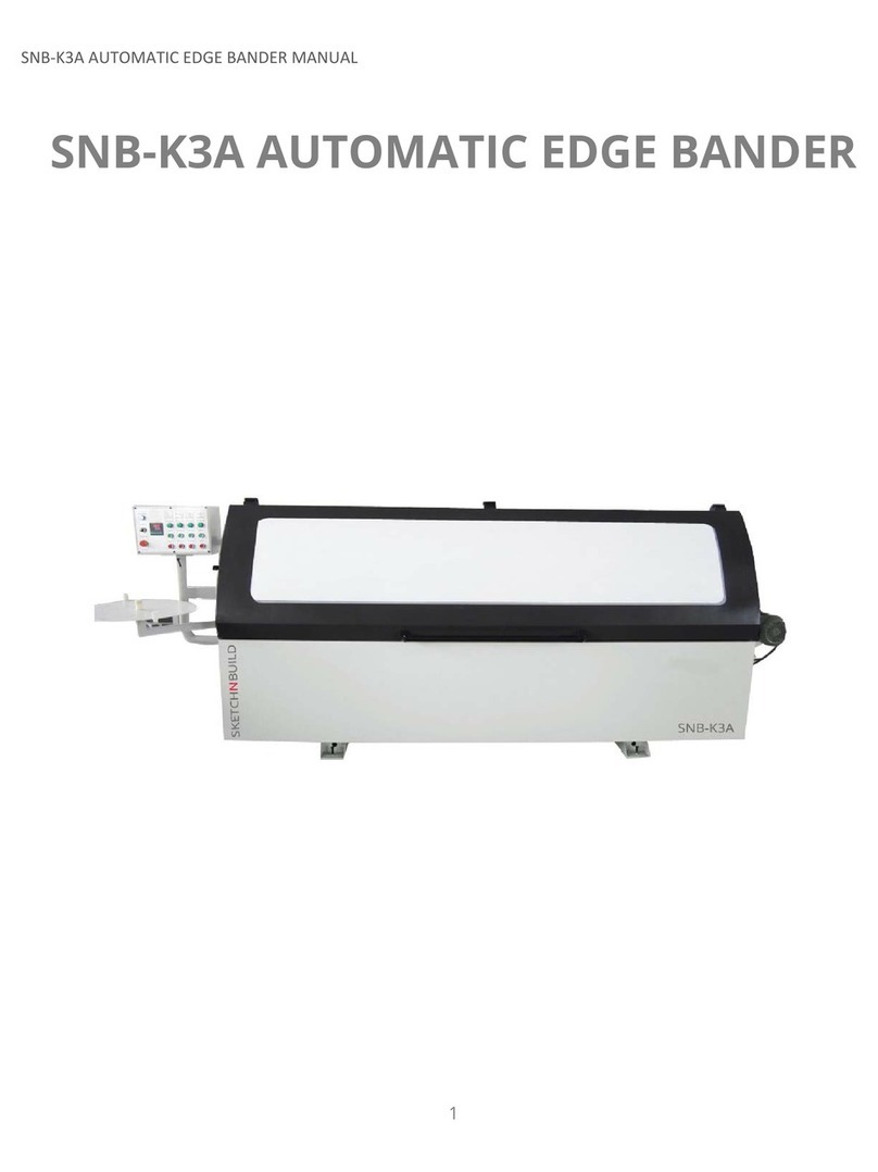
SKETCHNBUILD SNB-K2A User manual

SNB-K2A AUTOMATIC EDGE BANDER MANUAL
1
6/2016
SNB-K2A AUTOMATIC
EDGE BANDER
MANUAL

SNB-K2A AUTOMATIC EDGE BANDER MANUAL
2
6/2016
CONTENTS
1. SAFETY………………………………………………………………………………………………….……………….….3
2. SPECIFICATIONS & FEATURES……………………………………..………………………………………….…4
3. MACHINE PARTS……………………………………………………………..…………………………………….….6
4. TRANSPORTATION & INSTALLATION (WIRING)….………………..……………………………….…...8
5. OPERATION…………………………………………………………………………………………………….………..8
6. MAINTENANCE………………………………………………………………….…………………………………...17
7. PARTS LIST………………………………………………………………………………………………………………18
CAUTION: Read these instructions carefully before turning on the machine.

SNB-K2A AUTOMATIC EDGE BANDER MANUAL
3
6/2016
1. SAFETY
1. KEEP GUARDS IN PLACE and in working order
2. REMOVE ADJUSTING KEYS AND WRENCHES. Form a habit of checking to see that
keys and adjusting wrenches are removed from the machine before turning on.
3. KEEP WORK AREA CLEAN. Cluttered work areas invite accidents.
4. DO NOT USE IN HAZARDOUS OR DANGEROUS ENVIRONMENTS. Do no operate
machine in damp, wet locations or where any flammable or noxious fumes may
exist. Keep work area well lit.
5. KEEP CHILDREN, VISITORS and PETS AWAY. All children, visitors and pets should be
kept away and at a safe distance from work area. Make workshop child or pet proof
with padlocks, master switches and by removing starter keys.
6. DO NOT FORCE MACHINE. Machine will work safer at the rate in which it is designed
when not forced to operate.
7. USE THE RIGHT EQUIPMENT. Do not force machine or attachment to do a job for
which it is not designed.
8. WEAR PROPER SAFETY APPAREL. Do not wear loose clothing, gloves, neckties, rings,
bracelets or other jewelry which may get caught in moving parts. Non-slip footwear
is recommended. Wear protective hair covering.
9. ALWAYS USE SAFETY GLASSES. Also use a face or dust mask if work area is dusty.
Everyday eyeglasses only have impact resist lenses and they are NOT safety glasses.
10. SECURE WORK. Use clamps or a vise to hold work when working. It is safer than
using your hands and frees both hands to operate the machine.
11. DO NOT OVERREACH. Keep proper footing and balance at all times.
12. MAINTAIN MACHINE WITH CARE. Keep parts sharp and clean for safer performance.
Follow instructions for lubricating and changing accessories.
13. USE RECOMMENDED ACCESSORIES/PARTS. Use of improper accessories may cause
risk of injury.
14. RISK OF UNINTENTIONAL START. Always disconnect from power source before
adjusting or performing any maintenance. Make sure the switch is in the OFF
position before reconnecting.
15. KICKBACK. Many woodworking machines can “kickback” the work piece towards the
operator. Know what conditions can create “kickback” and learn how to avoid them.
16. DMAGED PARTS. Before further use of a part, guard or other part that is damaged,
check carefully to determine if it is able to operate properly and perform its
intended function. Check for alignment of moving parts, binding of moving parts,
broken parts, mounting or any other conditions that may affect its operation. A part
that is damaged should be replaced.

SNB-K2A AUTOMATIC EDGE BANDER MANUAL
4
6/2016
17. NEVER LEAVE THE MACHINE RUNNING OR UNATTENDED. TURN POWER OFF. Do not
leave the machine until it comes to a complete stop.
18. NEVER OPERATE THE MACHINE WHEN TIRED, OR UNDER THE INFLUENCE OF DRUGS
OR ALCOHOL. Full mental alertness is required at all times when running a machine.
19. NEVER ALLOW UNSUPERVISED OR UNTRAINED PERSONNEL TO OPERATE THE
MACHINE. Make sure any instructions given in regards to the operation of the
machine is safe and clearly understood.
2. SPECIFICATIONS & FEATURES
The SNB-K2A Automatic Edge bander is able to handle an array of material from PVC, ABS,
laminates, wood tape, and wood strips with thickness ranges from 0.5mm–3.0mm thick on
panels ranging anywhere from 14 - 40mm thick. For tapes up to 3 mm and plastic laminate
strips.
Features:
(a) Easy to adjust, high quality finishing
(b) Simultaneous adjustment for tape thickness, guide and gluing roller by a
single meter.
(c) Automatic feeder for tape rolls and end cutting system.
(d) Trimming unit at 9000 R/min.
(e) Automatic temperature control by the machine during all the working
process.
(f) Panel feeder with wide multi-layered belt.
(g) Front telescopic table extension with rollers.
Specifications:
(a) Motor Power: 3HP
(b) Power Source: 3Phase / 220v / 60Hz
(c) Minimum panel length –11 in
(d) Minimum panel width –3 ½ in
(e) Minimum edge thickness –0.4mm
(f) Maximum edge thickness –3mm
(g) Minimum panel thickness –3/8 in
(h) Maximum panel thickness –1 ¾ in
(i) Minimum Edge width –7/16 in
(j) Maximum edge width –1 7/8 in

SNB-K2A AUTOMATIC EDGE BANDER MANUAL
5
6/2016
(k) Dust Extraction Port –4”
(l) Air pressure - 0.6Mpa
(m)Feeding Speed –6.4m/min
(n) Buffing Motor –0.2 HP
(o) End Cutting Motor –0.16 HP
(p) Glue Tank Motor –0.2 HP
(q) Edge Seal Motor –0.2 HP
(r) Trimmer Speed –11000r/min
(s) Conveyor Belt Speed –6m/min
(t) Roller holder capacity –24 in diameter
(u) Tank capacity - 2.2 Pounds
(v) Work temperature - 347° F- 410° F
(w) Feeder motor power: - 0 .53 HP
(x) Trimmer motor power - 0.2 HP
(y) Gluing motor power -0.05 HP
(z) Total power –3.5HP

SNB-K2A AUTOMATIC EDGE BANDER MANUAL
6
6/2016
1
2
9
13
14
11
12
Fig. 2
5
6
7
8
10
4
3
Fig. 1
3. MACHINE PARTS
INSIDE & FRONT
1) Conveyor Belt 8) Edge Strip Conveyor
2) Conveyor Belt Height Setting 9) Edge Strip Support Table
3) Buffing Components 10) Edge Strip Conveyor and Cutter Switch
4) Trimming Components 11) Control Panel
5) End Tracking Components 12) Horizontal Expansion Table
6) Glue Tank 13) Back and Forth Expansion Table
7) Edge Trimmer 14) Terminal Cover

SNB-K2A AUTOMATIC EDGE BANDER MANUAL
7
6/2016
A
B
C
D
E
Fig. 3
BACK
A. Trimming & Cutting Adjustment D) Glue Tank Adjustment
B. Buffing Adjustment E) Rear End Plate
C. Glue Tank Bearing Greasing Hole

SNB-K2A AUTOMATIC EDGE BANDER MANUAL
8
6/2016
Fig. 4
4. TRANSPORTATION & INSTALLATION (WIRING)
1. Machine is delivered completely assembled. Choose a suitable location and check
that it is accessible from all sides.
2. The machine should be installed in a closed space. Working conditions of a
workshop are considered enough.
3. Floor surface should be even and stable, and if necessary, machine can be bolted to
the floor.
4. Install the extension worktable, and the support table for the edge strip to their
corresponding positions (see Figs 1/2/3 above).
5. Electrical: Take off the external terminal cover; connect 3 live lines separately to L1
、L2、L3,neutral line to N, earth line to PE (fig 4). Make sure to tighten the screws
to secure the wires.
5. OPERATION
1. Make sure the trimming motor is moving in the same cutting direction.
2. Ensure the pressure regulating valve for air pressure reads 0.6-0.8Mpa.
3. Adhesive must be a high-temperature hot melt glue which is to be applied at 350°F -
400°F and have a minimum speed of 7m/min.
4. Workpiece panels should be of the same thickness with a smooth surface. Make
sure the surface after being sealed is straight and level with no dust or oil and is
perpendicular to front side of the panel.
Edge banding strips should be from the same batch and have the same size.

SNB-K2A AUTOMATIC EDGE BANDER MANUAL
9
6/2016
1
2
3
4
5
6
7
8
Fig. 5
5. Make sure edge strip is clean with no oil contamination, tool marks or cracks.
Caution: Don’t run the machine until the temperature reaches 400°F, default factory
glue temperature setting is 400°F.
CONTROL PANEL
The functions of the control panel shown in Fig.5 are as follows:
1. Main switch: Off is 0and On 1; controls the machines power supply; digital thermometer
lights up. Turn the Key to the ON position and the machine is ready to operate. The
machine will not start up without opening the control system with the key.
2. Trimming and cutting components: designed to trim the upper and lower edge
overhang. Off is 0and On 1.
3. Automatic side-by-side end cut components are designed to cut before and after the
edge overhang, there are two buttons which control the rotation of the milling cutters,
Off is 0and On 1.
4. Automatic belt conveying device: Off is 0and On 1.
5. The top button is a time relay that controls the length of the edge strip being fed, and
the bottom button controls rotation of the glue roller and moves the edge strip. Off is 0
and On 1.
6. The meter on top indicates and controls the glue temperature. The bottom right button
is the heater switch. Off is 0and On 1. The lower left is a signal lamp, which indicates
that the switch is On and ready to operate.
7. Emergency switch: once the switch is impelled all functions will stop immediately, and
the switch is in a locked state. You have to turn the knob to the right to restore electric
transmission.

SNB-K2A AUTOMATIC EDGE BANDER MANUAL
10
6/2016
START UP
1. Make sure the work piece conveyor safety switch is off. The emergency stop switch
⑧should be in the “ON” position.
2. Access to power: Turn the power key to “On”, next, turn the main switch to make
the arrowhead point to “1”, at this point, all power is on and the power
indicator(green) and digital display temperature-controlled meter should light up.
3. Press the button ⑤to start the conveyor, and then check the direction of
movement to make sure it corresponds to the power connection instructions above.
If not, change the position of any two of the three live lines until it runs in the
correct direction.
4. After the conveyor runs in the right direction, turn the heating switch to “ON”, the
glue tank will start to heat up. (Caution: Do not run the machine until the
temperature reaches 400°F (default factory glue temperature setting is 400°F).
5. The machine is now ready to work
ADJUSTMENTS
Fig. 6
Fig. 7
B
E
C
N
D
Fig. 8
A
B
C
D

SNB-K2A AUTOMATIC EDGE BANDER MANUAL
11
6/2016
Installing the edge belt reel and the edge sealing belt regulator.
1. Put the edge sealing reel in the carrier as shown in Fig.6.
2. Push the edge sealing belt through the leading fields (2sets) as shown in Fig.7.
Adjust the upper cover plate B (loosen the locking knob C) according to the width of
the edge sealing belt, and push it through the roller to avoid tightening the edge
sealing belt.
3. Loosen bolt N and knob C so that base plate D and cover plate B rotate along
column E. Note: Base plate D needs to be in its normal position, it should be 18mm
between the topside of D and the table board, and the width of the edge sealing belt may
not be more than 2 mm on each side of the work piece. Ex: The maximum width of the
edge sealing belt should be 22mm if the thickness of a work piece is 18mm.
4. The edge sealing belt regulator as shown in Fig.8 consists of the base frame A, the
elastic sheet B, carrier C and adjusting screw D. Adjust the twisting screw D in
bracket C so that the edge strip produces adequate resistance between the elastic
sheet B and base frame A. Make sure it can move forward with adequate force and
can’t run freely in order for the edge strip to stay in position.
Mechanical Conveying of Edge Banding Belt
1. Once the temperature of glue reaches 400°F, and the glue roller and edge sealing
belt roller begin to rotate, press the “1” button in column ④as shown in Fig.5. The
edge banding process is now ready to begin.
Fig. 9
C
A
B

SNB-K2A AUTOMATIC EDGE BANDER MANUAL
12
6/2016
2. The operating distance of the knurl roll may be adjusted with 4 screw bolts
represented by B (as shown in Fig.9).
Caution! Don’t touch work piece or edge tape when a work piece entering into or leaving
the guillotine to avoid possible inquiry. Make sure to cut off the machine’s power before
servicing.
Trimming the edge bander from the edge sealing belt disc.
1. The cutting clamp begins to operate when a work piece reaches the micro switch A
in Fig.10.
Glue Tank Components
Fig. 10
A
Fig. 11
A
B
Fig. 12
A
B

SNB-K2A AUTOMATIC EDGE BANDER MANUAL
13
6/2016
The glue tank components apply melted glue onto the work piece to be sealed.
1. Put glue pellets inside the glue tank, and its liquid is about 1 cm from the edge.
2. Adjust the temperature controller to the suggested temperature F (default factory
glue temperature setting is 400°F) Adjust the temperature as required.
3. Start the glue roller once the glue temperature is achieved. The amount of glue
applied may be controlled by adjusting level B (Fig.11).
4. Pay attention to amount of the glue while sealing and add glue to the tank to
maintain the liquid level at 1cm from the edge.
5. Turn off the machine to add grease oil. Use special oil gun to inject high
temperature grease into oil hole A as shown in Fig.12.
Caution! Hot surface inside! Do not touch! To avoid possible skin in burns, disconnect and
lockout power and allow surfaces to cool down before servicing.
Automatic side-by-side end trimming components
The components are designed to automatically cut any unwanted edging before and after
(side-by-side for short).In order to ensure that the sealing belt’s section is similar with that
of the material.
Fig. 13
3
2
1
9
7
8
5
6
4

SNB-K2A AUTOMATIC EDGE BANDER MANUAL
14
6/2016
The functions of the major parts are as follows:
①Front side-by-side and follow-up control switch
②Follow-up control switch
③Longitudinal guide rail along with motor and side-by side saw blade slide
longitudinally
④Back stroke control switch
⑤Side-by-side control switch
⑥Side-by-side saw drive motor
⑦Vertical guide rail
⑧Front side-by-side saw blade
⑨Rear side-by-side saw blade
Caution! Moving saw blades for end cutting are in high-speed rotation when the machine is
running. Don’t touch to avoid injury! Make sure to turn off the machine’s power and allow the
saws to stop spinning before making any adjustments or replacement.
Leveling & Trimming Functions
1. Milling Cutter: Adjustments are as shown in Fig. 14 & Fig. 15
2. The components level and trim extra edge banding on both sides (upper & lower).
You may obtain different sealing effects such as common angle, inclined angle or
rounded angle according to cutter selected and thickness of edge banding used. The
components are equipped with two cutters 2⅞” in diameter, which rotate in the
reverse milling. There are 6 cutter heads with a standard cutting angle of 1.5mm
each and spin at 11000r/min.
3. The height of upper trimming cutter may be automatically adjusted by connecting
rod A in Fig.15 to change height of the work piece conveyor to fit the thickness of
the work piece.
4. There is a 4” diameter dust exhauster located in the upper and lower cutters to
clean trimmed waste residues. The air force of dust absorption is 0.75miles/minute.
Caution! Moving cutters are in high-speed rotation when machine is running. Do not
touch to avoid injury! Don’t touch to avoid injury! Make sure to turn off the machine’s
power and allow the cutters to stop spinning before servicing.

SNB-K2A AUTOMATIC EDGE BANDER MANUAL
15
6/2016
Adjustment of leveling Components
1. The components are equipped with two adjusting systems in which one is the axial
cutter and the other is a vertical detector. The axial adjustment may move the cutter
by adjusting two knobs: C and D (Fig.15). This adjustment is frequent and needs to
be made while the cutter is operating.
2. There is a direction board at the back of the machine as shown in Fig.16 (”+”)
forward and (“-”) backward. The vertical adjustment in radial direction may be made
by adjusting bolts F and G (in Fig.14) to change the clearance of detector E to be
accommodate the changes in the cutter diameter. This adjustment should be made
while changing the cutter (when the cutter becomes blunt).
Note: bolts F and G need to be adjusted to the same number of turns so that the
detector and the worktable are parallel. The maximum width of the edge banding
beyond both sides of the work piece is 2mm each side (as shown in Fig. 17).
Fig. 14
G
G
F
F
E
Fig. 15
D
C
A
Fig. 16
Fig. 17

SNB-K2A AUTOMATIC EDGE BANDER MANUAL
16
6/2016
Workpiece Conveyor
1. The conveying system for work pieces to be sealed consists of a high-density friction
belt. It not only guarantees that the work piece moves forward but it also it makes
the work piece remain on the glue roller with the assistance of the table rubber
rollers to ensure no damage is done to the work piece.
Note: the belt should be used at full width to avoid skidding or being damaged.
2. The conveyor is operated by three-phase motor reducer. Wheel handle B in Fig.18
controls the conveyor D to ascend and descend.
3. The height of the conveyor adjustment in proportion to the work piece thickness
may be read on counter A as shown in Fig.18. Loosen handle C in Fig. 18 before
adjusting the height of the conveyor.
Caution! Moving parts can crush and cut .Keep guards in place. Make sure to turn off the
machine’s power before servicing.
Fig. 18
D
A
B
E
C
Fig. 19
A
1

SNB-K2A AUTOMATIC EDGE BANDER MANUAL
17
6/2016
TRIAL RUN
1. Push work piece frame and edge strip frame to the pre-calculated position.
2. Adjust the height of conveyor by the hand wheel in Fig.18 to ensure it corresponds
to thickness of a work piece.
3. Add glue to the tank A in Fig.11 to the required level of ¼” from top.
4. Start the machine when the glue temperature reaches 400°F
5. Press the gluing button in column⑥(Fig.5) and the edge strip conveyor button in
column ⑥as shown in Fig.5. The amount of glue applied can be controlled by
adjusting lever B (Fig.11).
6. Start all the other switches in succession.
7. Place the panel against the work piece conveyor, and move the work piece with the
conveyor belt to complete the sealing process.
6. MAINTENANCE
1. Make sure to First Turn-off power before any repair and maintenance is started.
Follow the application requirements.
2. It is essential to keep the machine clean to ensure the quality to avoid accident and
so as to extend the machine’s service life.
3. Don’t run the machine unless the work environment is good and all safety
protection covers, dust exhausters are working normally to avoid emission of chips
and dust.
4. Do Not Open the electrical cabinet unless servicing the machine.
5. Make sure to use trained service technicians to service the machine.
6. Clean up the dust outer and inside of the machine completely during storage. Keep
the machine and the environment clean and tidy inside plastic sheeting and with
engine oil on it to avoid rust.
7. Moving parts must be lubricated often. Good lubrication ensures a longer life of the
machine.

SNB-K2A AUTOMATIC EDGE BANDER MANUAL
18
6/2016
7. PARTS LIST
①Pressure regulating valve
②Air units
③Follow-up time relay
④Manual button of rim charge magnet valve
⑤Tool magnet valve cut off
⑥Manual tool magnet valve cut off
⑦Side-by-side and follow-up magnet valve
⑧Manual button of side-by-side and follow-up magnet valve
⑨Side-by-side saw descending throttle valve
Fig. 20
3
4
5
6
8
7
10
9
11
12
13
14
1
2

SNB-K2A AUTOMATIC EDGE BANDER MANUAL
19
6/2016
⑩Manual button of side-by-side saw lifting magnet valve
⑪Side-by-side descending throttle valve
⑫Side-by-side saw lifting throttle valve
⑬Side-by-side advancing throttle valve
⑭Side-by-side backset throttle valve
BEARINGS LIST
Location
Model
Dimensions(mm)
Qty
Remarks
Glue Process upright shaft
SNB6005
25x47x12
2
Normal speed
and not sealed
Glue pot supporting rack
SNB6005
25x47x12
2
Normal speed
and not sealed
Rim charger rubber roller
SNB6002
15x32x9
2
Normal speed
and not sealed
Cross sliding block clutch-lower
SNB6203
17x40x12
2
Normal speed
and not sealed
Transition steel roller
SNB6202
15x32x11
4
Normal speed
and not sealed
Pressing rubber roller
SNB6002
15x32x11
2
Normal speed
and not sealed
Milling cutter shafts-upper & lower
SNB6002
15x32x9
4
Normal speed
and not sealed
Conveyor belt axle head
SNB6002
15x32x9
1
Normal speed
and not sealed
Conveyor belt roller
SNB6004
20x42x12
2
Normal speed
and not sealed
Carrying roller
SNB6004
20x42x12
28
Normal speed
and not sealed
Side-by-side saw
SNB6002
15x32x9
2
High Speed
and fully
sealed
Buffing shafts-upper & lower
SNB6002
15x32x9
4
High Speed
and fully
sealed
Follow up roller
SNB6002
15x32x9
4
Second High
Speed and fully
sealed

SNB-K2A AUTOMATIC EDGE BANDER MANUAL
20
6/2016
Plate thickness adjustor
SNB51201
12x28x11
2
Planer Bearing
Milling cutter carrier
SNBLM12UU
12x21x30
10
Linear Bearing
Buffing carrier
SNBLM12UU
12x21x30
10
Linear Bearing
Side-by-side vertical guide rail
SNBLM12UU
12x21x30
4
Linear Bearing
Side-by-side horizantal guide rail
SNBLM12UU
12x21x36
4
Linear Bearing
Table of contents
Other SKETCHNBUILD Industrial Equipment manuals
Popular Industrial Equipment manuals by other brands

Adkins
Adkins Alpha Calender Roll-Master 1.2 Operator's handbook
Tanco
Tanco E100 SA Quick reference guide

Sumitomo Drive Technologies
Sumitomo Drive Technologies HF-430NEO Series Operating and maintenance manual

PCB Piezotronics
PCB Piezotronics ICP 320C15 Installation and operating manual
PACLITE Equipment
PACLITE Equipment IMPACT430DE Operator's manual

Toro
Toro 110-5076 installation instructions
