DINAMIC OIL SA Series User manual

1
Gearboxes - Hoists - Winches - Construction Attachments
SA Series Users Manual . Release 01 . English
December 8, 2021 . Release 01 . English
North America Edition
USERS MANUAL
SAFETY, OPERATION, MAINTENANCE
SA SERIES ANCHOR DRIVE
SA5, SA6, SA6L, SA7, SA8, SA12, SA16, SA20, SA30
Dinamic Oil North America
4725 Entrance Drive, Suite A
Charlotte, NC 28273
dinamicoil.us
© 2021 Dinamic Oil North America All Rights Reserved
SA
SERIES
Printed in the USA.

2SA Series Users Manual . Release 01 . English
Gearboxes - Hoists - Winches - Construction Attachments
PREFACE
This manual contains information for the safe operation and maintenance of your Dinamic Oil attachment. Read the
entire manual before the initial start-up of the attachment. It is important to know the correct operating procedures of the
attachment and all safety precautions to prevent the possibility of property damage and personal injury.
The attachment has been designed and manufactured with quality materials and care in workmanship. The instructions in
this manual have been prepared to ensure that, when followed properly, the attachment will provide ecient and reliable
service. Continuing product development and improvement may have caused changes in the attachment that are not
reected in this manual. If a question arises regarding the attachment, contact a Dinamic Oil dealer for the most current
information available.
INTRODUCTION
Thank you for purchasing your new product! Dinamic Oil attachments are designed for use with specic mounting frames
and linkage to be used with the prime mover. Provided these are used and maintained correctly, the products will provide
a safe and ecient method of use.
Before operating your attachment, please note:
• The planetary drive comes complete, lled with the correct amount of gear oil.
• Hydraulic hoses must be tted and tightened correctly.
• If a case drain hose is required, it must be used and tted correctly.
• The attachment must be broken-in per the recommended procedure.
IMPORTANT
This manual must accompany the attachment at all times and be readily available to the operator. This operating manual
should be used in conjunction with the prime movers operating instructions.
MANUAL REPLACEMENT
Should this manual become damaged, lost or additional copies are required, immediately contact any authorized Dinamic
Oil dealer. You may also download a PDF copy at www.dinamicoil.us.
POSSIBLE VARIATIONS
Dinamic Oil cannot anticipate every possible circumstance that might involve a potential hazard, as
the owner’s requirements and equipment may vary. Therefore, the warnings in this publication and on the product
may not be all- inclusive and you must ensure that the procedure, application, work method and operating technique is
safe for you, and others, before operation.
PUBLIC NOTICE
Dinamic Oil reserves the right to make changes and improvements to it’s products and technical literature at any time,
without public notice or obligation. Dinamic Oil also reserves the right to discontinue manufacturing any product at it’s
discretion, at any time.
WARRANTY
All work or repairs to be considered for warranty reimbursement must be authorized by the Dinamic Oil Service
Department before work is started. Any alterations, modications or repairs performed before authorization by the
Dinamic Oil Service Department will render all warranty reimbursement consideration null and void. Improper operation or
improperly performed maintenance may render any warranty null and void.

3
Gearboxes - Hoists - Winches - Construction Attachments
SA Series Users Manual . Release 01 . English
TABLE OF CONTENTS
SAFETY
Preface / Introduction .......................................................................................................................................... 2
Table of Contents .......................................................................................................................................... 3
Declaration of Conformity (CE) ........................................................................................................................... 4
General Safety Precautions ...............................................................................................................................5-9
Safety Decal Info. / Serial Tag Info. .................................................................................................................... 10
PRODUCT SPECIFICATIONS / PERFORMANCE
Part Numbers and Codes ...................................................................................................................................11
Product Specications SA Series ...................................................................................................................... 12
Product Specications SA Series Cont. ............................................................................................................ 13
INSTALLATION
Mounting Kit Installation .................................................................................................................................... 14
Hydraulic Installation / Cold Weather / Break-In ................................................................................................ 15
OPERATION / MAINTENANCE
Lubrication Information ...................................................................................................................................... 16
Operating Temperature Guidelines .................................................................................................................... 17
Oil Check and Filling / Service Schedule .......................................................................................................... 18
Torque Chart For Common Bolt Sizes ............................................................................................................... 19
WARRANTY
Warranty Information .......................................................................................................................................... 20

4SA Series Users Manual . Release 01 . English
Gearboxes - Hoists - Winches - Construction Attachments
DECLARATION OF CONFORMITY
DECLARATION OF CONFORMITY
ÜBEREINSTIMMUNGS-ERKLARUNG
DECLARATION DE CONFORMITE CEE
DECLARACION DE CONFORMIDAD
DICHIARAZIONE DI CONFORMITA
I, the undersigned:
Ich, der Unterzeiche:
Je soussigné:
El abajo rman:
lo sottoscritto:
hereby declare that the equipment specied hereunder:
bestätige hiermit, daß erklaren Produkt genannten Werk oder Gerät:
déclare que l’équipement visé ci-dessous:
Por la presente declaro que el equipo se especica a continuación:
Dichiaro che le apparecchiature specicate di seguito:
Philip Joyce, President - North America
Category/Kategorie/Catégorie/Categoria/Categoria:
Make/Marke/Marque/Marca/Marca
Type/Typ/Type/Tipo/Tipo:
Serial number of equipment:
Seriennummer des Geräts:
Numéro de série de l’équipement:
Numero de serie del equipo:
Matricola dell´attrezzatura:
Has been manufactured in conformity with
Wurde hergestellt in Übereinstimmung mit
Est fabriqué conformément
Ha sido fabricado de acuerdo con
E’ stata costruita in conformitá con
Directive/Standards
Richtlinie/Standards
Directives/Normes
Directriz/Los Normas
Direttiva/Norme
Representative in the Union:
Vertreter in der Union
Représentant dans l’union
Representante en la Union
Rappresentante presso l’Unione
Position/Position/Fonction/Cargo/Posizione
Planetary Anchor Drive Attachment
Dinamic Oil
SA and TA Series
All
EN 12100-1:2010 - Safety of Machinery
EN 16228-1:2014 - Drilling and Foundation Equipment. Common req.
EN 16228-4:2014 - Drilling and Foundation Equipment. Fnd Equip.
EN 16228-7:2014 - Drilling and Foundation Equippment. Aux Equip.
2006/42/EC - Machinery Directive
2000/14/EC - Noise Emission
Eris Lanciotti
Dinamic Oil S.p.A. con Socio Unico
Via Togliatti, 15
41030 Bomporto - MO - Italy
Technical Manager
5
Gearboxes - Hoists - Winches - Construction Attachments
SA Series Users Manual . Release 01 . English
SAFETY STATEMENTS
Your safety and the safety of others is a direct result of how you operate and maintain your equipment. Read and
understand this manual and other safety information provided with the base machine and be sure that you understand all
controls and operating instructions before attempting to operate this equipment. Failure to follow the safety precautions
can result in personal injury, death or property damage.
Dinamic Oil cannot foresee all hazardous circumstances, the precautions listed in this manual and on the equipment are
not all-inclusive. If a procedure, method, tool or part is not specically recommended by Dinamic Oil, determine whether
it is safe for you and others, and that the equipment will not be damaged or made unsafe as a result of your decision to
implement it. The basic rules are summarized in this section of the manual. They also appear throughout the manual
along with additional specic rules for safety and operation.
Carefully read all safety messages in this manual and on your equipment safety signs. Keep safety signs in good
condition. Replace missing or damaged safety signs.
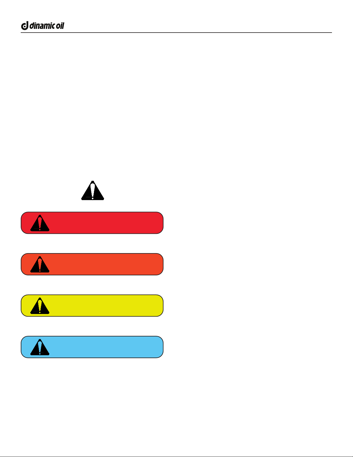
SAFETY ALERT SYMBOLS AND SIGNAGE
Never compromise on safety! It can cause serious injury or death! All operators must read and fully understand all of
the safety instructions and alert symbols.
DANGER
WARNING
CAUTION
NOTICE
Indicates an imminently hazardous situation
which will result in death or serious injury.
The Safety Alert Symbol alerts you to potential personal injury
hazards. Obey all safety messages.
Indicates a potential hazardous situation which
could result in death or serious injury.
Indicates hazards that could result in damage
to the equipment or personal injury.
Indicates important procedures.

6SA Series Users Manual . Release 01 . English
Gearboxes - Hoists - Winches - Construction Attachments
READ MANUAL PRIOR TO INSTALLATION
Improper installation, operation, or maintenance of
this equipment could result in serious injury or death.
Operators and maintenance personnel should read this
manual,as well as all manuals related to this equipment
and the prime mover thoroughly before beginning
installation, operation, or maintenance.
READ AND UNDERSTAND ALL SAFETY
STATEMENTS
Read all safety decals and safety statements in all
manuals prior to operating or working on this equipment.
Know and obey all regulations, local laws, and other
professional guidelines for your operation.
Know and follow good work practices when assembling,
maintaining, repairing, mounting, removing, or operating
this equipment.
KNOW YOUR EQUIPMENT
Know your equipment’s capabilities, dimensions, and
operations before operating.
Visually inspect your equipment before you start, and
never operate equipment that Is not in proper working
order with all safety devices intact.
Check all hardware to ensure it is tight. Make certain that
all locking pins, latches, and connection devices
are properly installed and secured.
Remove and replace any damaged, fatigued, or
excessively worn parts.
Make certain all safety decals are in place and are
legible.
Keep decals clean, and replace them if they become
worn or hard to read.
PRIME MOVER LIFT CAPACITY
Alert yourself to the weight of the Drive attachment. DO
NOT exceed the recommended lift capacity of the prime
mover. Refer to your prime mover’s owners manual for
suggested lift capacity and lift considerations.
NOTICE
DO NOT MODIFY EQUIPMENT / PRODUCT
Modications may weaken the integrity of the attachment
and may impair the function,safety, life, and performance
of the attachment.
When making repairs, use only the manufacturer’s
genuine parts, following authorized instructions. Other
parts may be substandard in t and quality.
Never modify any ROPS (Roll Over Protective Structure)
or FOPS (Falling Object Protective Structure) equipment
or device. Any modications must be authorized in
writing by the manufacturer.
RAISED EQUIPMENT CAUTION
DO NOT work under raised booms without supporting
them.
Never place any body part between the prime mover
chassis and the attachment.
Do not use support materials made of concrete blocks,
logs, buckets, barrels, or any other material that could
suddenly collapse or shift positions. Make sure support
material is solid, not decayed,warped, twisted, or tapered.
Lower booms and attachments to the ground before
leaving the cab or operator’s station.
Whenever the boom structure must be raised for
attachment installation or servicing ensure the boom
locking devices (if equipped) are deployed to prevent the
accidental lowering of boom structures.
CALIFORNIA PROPOSITION 65 WARNING
This product may contain a chemical known to the
state of California to cause cancer, or birth defects or
other reproductive harm. www.P65Warnings.ca.gov
For Customers in California, pursuant to California Health
and Safety Code Section 25249.5 et seq., commonly
referred to as Proposition 65 (“Prop 65”), DONA hereby
noties Buyer that the Goods sold contain shale oils,
mineral oils, and tetrachloroethylene, which are known to
the State of California to cause cancer.
WARNING
WARNING

7
Gearboxes - Hoists - Winches - Construction Attachments
SA Series Users Manual . Release 01 . English
OPERATOR SAFETY
Safety equipment should be worn at all times when
viewing, operating or maintaining the attachment.
Safety equipment includes eye protection, hard hat, steel
toe shoes, gloves and hearing protection.
Wear protective clothing and equipment appropriate for
the job. Avoid loose tting clothing.
Prolonged exposure to excessive noise can cause
hearing loss. Wear suitable hearing protection such as
ear plugs.
Operating equipment safely requires the full attention of
the operator. Avoid distractions.
Operate only from the operator’s cab/station.
Reduce speed when driving over rough terrain, on a
slope, or turning, to avoid overturning the vehicle.
Travel only with the attachment in a safe transport
position to prevent uncontrolled movement.
Drive slowly over rough ground and on slopes.
Before exiting the machine, lower the attachment to
the ground, apply the parking brakes, turn o the prime
mover’s engine and remove the key.
Flow and pressure gauges, ttings, and hoses must
have a continuous operating pressure rating of at least
25% higher than highest pressures of the system.
Do not operate the unit when you are tired, ill or under the
inuence of alcohol, drugs or medication.
Never let a minor or inexperienced person operate the
unit.
Keep all body parts away from rotating objects.
Inspect the ground area before operation. Remove
objects which can be thrown or become entangled.
DO NOT operate the attachment in areas where carbon
monoxide fumes can accumulate.
Be alert when operating in locations where any type of
landscaping fabric/mat may be present. The material
can be rapidly drawn into the point of operation, possibly
causing injury or death to anyone standing on or near the
fabric.
PRODUCT SAFETY
NEVER suspend the attachment over people or
equipment. Maintain a safe distance of at least 30 feet
(10 meters).
Inspect the entire product before operation.
Replace parts that are cracked, chipped or damaged in
any way before operation.
Keep others away when making any adjustments to the
unit.
If the attachment is not functioning properly, shut down the
machine, follow proper Lock-out / Tag-out procedures.
NEVER approach power lines with any part of the
machine. Keep clear at a minimum of 15 feet (5 meters).
Avoid working on unstable or slippery areas and position
the prime mover on rm, level ground.
Tether any anchor or extensions connected to the
Anchor Drive with a chain if necessary, to prevent
uncontrolled swinging of the attachments when moving
from position to position.
Side loading is NOT recommended. Excessive side
loading can cause output shaft deection and or failure.
Avoid excessive side loading to prevent possible
instantaneous output shaft failure. Such a failure could
result in injury from disconnected parts and or being hit by
the Drive attachment causing serious injury or death.
Anchor Drive attachments shall be used only for
their designed intent and shall not be loaded beyond
their rated capacity. Overloading or exceeding the
manufacturers specications will void all warranty.
UNDERGROUND HAZARDS
It is the responsibility of the operator to know where buried
power, gas, telephone, and other utilities are at in the work
area.
This may lead to shock or an explosion. Have the work
area marked for buried lines and do not dig in marked areas
set by your local municipals.
WARNING

8SA Series Users Manual . Release 01 . English
Gearboxes - Hoists - Winches - Construction Attachments
BE ALERT ON THE JOB SITE
Tragic accidents can occur if the operator is not alert to the
presence of bystanders.
Children in particular are often attracted to machinery
and work activity. Never assume that children will
remain where you last saw them.
BE ALERT and turn the equipment o if children enter the
work area. Keep children out of the work area and under
supervision of another responsible adult.
SILICA DUST CAUTION
Exposure to respirable crystalline silica dust along
with other hazardous dusts may cause serious or
fatal respiratory disease.
Concrete and masonry products contain silica sand.
Quartz, which is a form of silica and the most common
mineral in the earths crust, is associated with many types
of rock. Some activities that silica dust may be present
in the air include demolition, sweeping, loading, sawing,
hammering, drilling, or planing of rock, concrete or
masonry.
It is recommended to use dust suppression, dust
collection or personal protective equipment during the
operation of any attachment that may cause high levels of
silica dust.
The NIOSH recommended exposure limit for respirable
crystalline silica is 0.05 mg/m3 as a time-weighted
average for up to 10 hours/day during a 40-hour work
week [NIOSH 1974].
PRACTICE SAFE MAINTENANCE
Use proper tools and equipment when conducting
maintenance. Work in a clean dry area.
Inspect all parts. Be sure parts are in good working
condition and installed properly. Remove build up of
grease, oil or any debris.
Remove all tools and unused parts from equipment before
beginning operation.
CAUTION
REMOVE PAINT BEFORE WELDING OR
HEATING
Hazardous fumes/dust can be generated when paint is
heated by welding, soldering or using a torch. Do all work
outside or in a well ventilated area and dispose of paint
and solvent properly. Remove paint before welding or
heating.
When sanding or grinding paint, avoid breathing the
dust. Wear an approved respirator.
If you use solvent or paint stripper, remove stripper with
soap and water before welding. Remove solvent or paint
stripper containers and other ammable material from
area. Allow fumes to disperse at least 15 minutes before
welding or heating.
SOUND AND VIBRATION
Sound pressure levels and vibration data for this
attachment are inuenced by many dierent
parameters: some items are listed below (not inclusive):
Prime mover type, age, condition, with or without cab
enclosure and conguration
Operator training, behavior, stress level.
Job site organization, working material condition,
environment
Based on the uncertainty of the prime mover, operator,
and job site, it is not possible to get precise machine and
operator sound pressure levels or vibration levels for this
attachment.
END OF LIFE DISPOSAL
At the completion of the useful life of the unit, drain all
uids and dismantle by separating the dierent materials
(rubber, steel, plastic, etc.). Follow all governmental and
local regulations for recycling and disposal of the uid and
components.
CAUTION
WARNING
9
Gearboxes - Hoists - Winches - Construction Attachments
SA Series Users Manual . Release 01 . English
TRANSPORTING THE DRIVE ATTACHMENT
Travel only with the Drive attachment in a safe transport
position to prevent uncontrolled swinging. Tether the
Drive attachment with a chain, if necessary, to prevent
uncontrolled swinging of the attachment when moving
from hole to hole.
Remove the earth auger or helical pile from the Drive
attachment before transporting to and from the job site.
Use extreme care during transport to prevent contact
between the Drive attachment and bystanders or
solid objects. Contact with the Drive attachment
could cause serious damage, injury or death.
Never operate the Drive attachment while
transporting.
Drive slowly over rough ground and on slopes. Position
the Drive attachment as low to the ground as possible
maintaining a low center of gravity.
Verify that all tie down accessories (chains, slings, ropes,
shackles and etc.) are capable of maintaining attachment
stability during transporting and are attached in such a
way to prevent unintended disengagement or shifting of
the unit. Failure to do so could result in serious personal
injury or death.
HYDRAULIC FLUID PRESSURE
Hydraulic uid under pressure can penetrate the skin and
cause serious injury or death.
Hydraulic leaks under pressure may not be visible. Before
connecting or disconnecting hydraulic hoses, read your
prime mover’s operator’s manual for detailed instructions
on connecting and disconnecting hydraulic hoses or
ttings.
Keep unprotected body parts, such as face, eyes, and
arms as far away as possible from a suspected leak.
Flesh injected with hydraulic uid may develop
gangrene or other permanent disabilities.
Hydraulic oil becomes hot during operation. DO NOT
come in contact with hot hydraulic oil as it could
cause severe burns. Wear adequate protective
clothing and safety equipment.
DO NOT tamper with hydraulic lines or components
while they are pressurized. Escaping uid under
pressure can penetrate the skin, causing serious
injury. Keep hands and body away from pinholes and
nozzles which eject uids under high pressure.
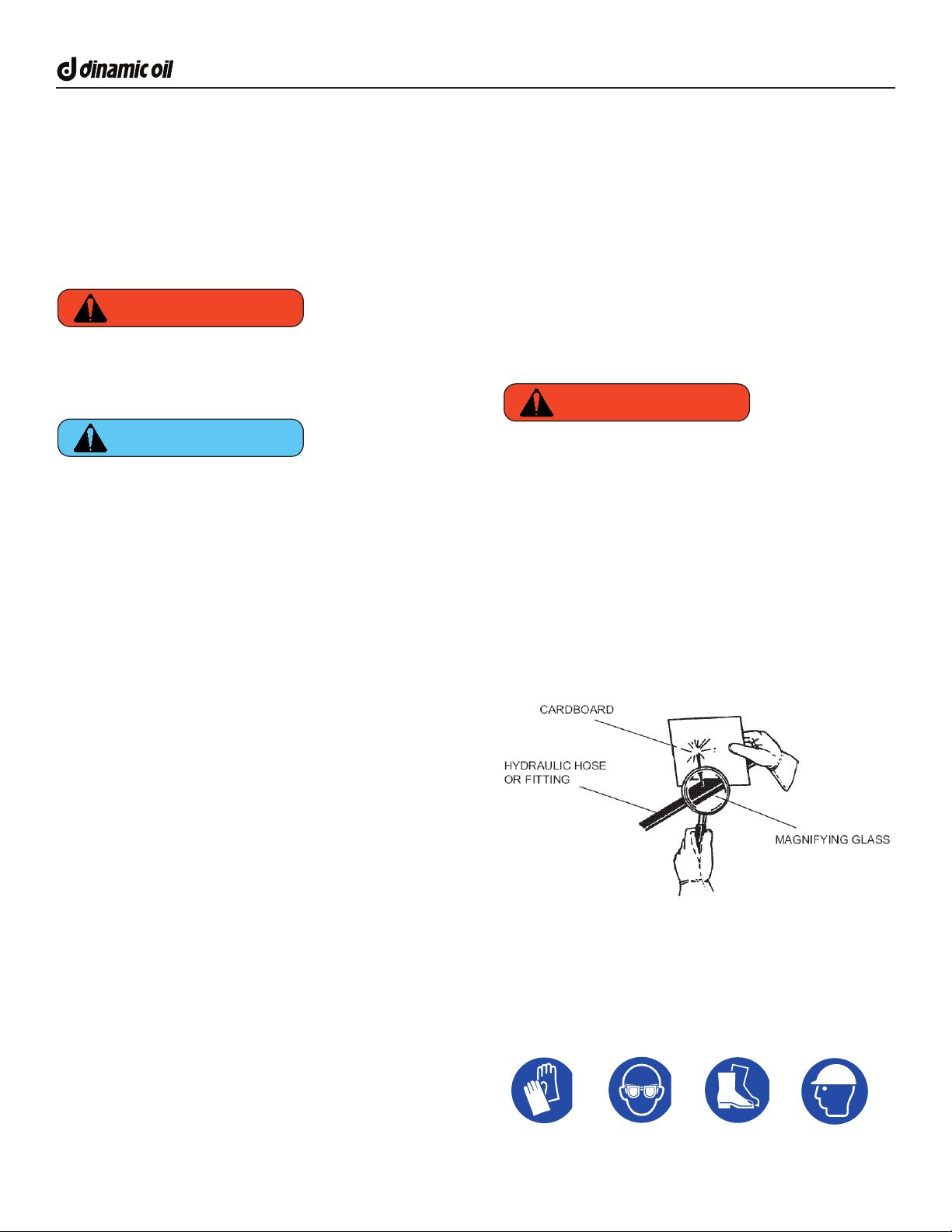
Wear safety glasses, protective clothing, and use a piece
of cardboard or wood when searching for hydraulic leaks.
DO NOT USE YOUR HANDS! SEE ILLUSTRATION.
WARNING
NOTICE
WARNING
Safety equipment should be worn at all times when
working with hydraulics.
Safety equipment includes eye protection, hard hat,
steel toe shoes, gloves and hearing protection. Wear
protective clothing and equipment appropriate for the
job. Avoid loose tting clothing.

10 SA Series Users Manual . Release 01 . English
Gearboxes - Hoists - Winches - Construction Attachments
SERIAL TAG INFORMATION
Its important to make the correct reference to the serial number of the
unit when making repairs or ordering parts. The serial number plate will
be located near the top of the Drive attachment.
SAFETY DECALS
The Drive attachment comes equipped with all safety decals in place. They are designed to help you safely operate your unit.
Read and follow all safety decals.
Keep all safety decals clean and legible at all times.
Replace safety decals that are missing or have become illegible.
Safety decals are available from your distributor or manufacture.
Some parts installed during repair may require safety decals to be axed to the replacement part. When ordering the
replacement part(s) be sure the correct safety decal(s) are included in your order.
INSTALLING SAFETY DECALS
Clean the desired area with warm soapy
water.
Decide on exact position before you remove
the backing paper.
Peel backing paper from decal. Press rmly
on the surface.
Remove all air pockets. Air pockets can be
pierced with a pin and smoothed.
NOTICE
Dinamic Oil North America
4725 Entrance Drive, Suite A
Charlotte, NC 28273
dinamicoil.us I 704.587.4600
Assembled
in the USA
Part Number Model
TD FLANGE
Serial Number
32521345
521250108 029813261
Nov-2021Serial Number
NASA012501 SA12-BE
WARNING
CALIFORNIA PROPOSITION 65
CANCER AND REPRODUCTIVE HARM
www.P65warnings.ca.gov
DR50785
WARNING
PINCH POINT
HAZARD
KEEP CLEAR
DR50791
UNDERGROUND
HAZARD
READ MANUAL
HIGH-PRESSURE
FLUID HAZARD
FLUID OR THROWN
OBJECT HAZARD
STAY 20 FEET (6m) AWAY FROM
ATTACHMENT DURING OPERATION.
DO NOT WORK
UNDER EQUIPMENT
AVOID INJURY OR DEATH
ENTANGLEMENT
HAZARD
DR50792
CAUTION
KEEP ALL HYDRAULIC HOSES,
FITTINGS AND COUPLERS TIGHT
AND FREE OF CONTAMINATION
AND LEAKS.
MAX PRESSURE
3000 PSI (207 BAR)
DR50808
NADCL00106 - SA20-B DECAL MASTER SHEET
Decal Kit Example

11
Gearboxes - Hoists - Winches - Construction Attachments
SA Series Users Manual . Release 01 . English
PART NUMBERS AND CODES (TA MODELS)
The list below outlines all TA series Anchor Drive models and congurations.
SA5
Part Number Description
NASA005100 Anchor Drive SA5-A
NASA005600 Anchor Drive SA5-AE
NASA005200 Anchor Drive SA5-C
NASA005400 Anchor Drive SA5-CE
NASA005300 Anchor Drive SA5-B
NASA005500 Anchor Drive SA5-BE
SA6
Part Number Description
NASA006100 Anchor Drive SA6-A
NASA006600 Anchor Drive SA6-AE
NASA006200 Anchor Drive SA6-C
NASA006400 Anchor Drive SA6-CE
NASA006300 Anchor Drive SA6-B
NASA006500 Anchor Drive SA6-BE
SA6L
Part Number Description
NASA06L100 Anchor Drive SA6L-A
SA7
Part Number Description
NASA007100 Anchor Drive SA7-A
NASA007600 Anchor Drive SA7-AE
NASA007200 Anchor Drive SA7-C
NASA007400 Anchor Drive SA7-CE
NASA007300 Anchor Drive SA7-B
NASA007500 Anchor Drive SA7-BE
SA8
Part Number Description
NASA008200 Anchor Drive SA8-C
NASA008400 Anchor Drive SA8-CE
NASA008300 Anchor Drive SA8-B
NASA008500 Anchor Drive SA8-BE
SA12
Part Number Description
NASA012200 Anchor Drive SA12-C
NASA012400 Anchor Drive SA12-CE
NASA012300 Anchor Drive SA12-B
NASA012500 Anchor Drive SA12-BE
SA16
Part Number Description
NASA016200 Anchor Drive SA16-C
NASA016400 Anchor Drive SA16-CE
NASA016300 Anchor Drive SA16-B
NASA016500 Anchor Drive SA16-BE
SA30-BE
Series
“SA”
Model
5, 6, 6L, 7, 8, 12, 16, 20, 30
Conguration
A = Motor & Gearbox
AE = Motor, Gearbox, Energi
C = Crown
B = Bail
CE = Crown Energi
BE = Bail Energi
Model Code Example
SA20
Part Number Description
NASA020300 Anchor Drive SA20-B
NASA020500 Anchor Drive SA20-BE
SA30
Part Number Description
NASA030300 Anchor Drive SA30-B
NASA030500 Anchor Drive SA30-BE

12 SA Series Users Manual . Release 01 . English
Gearboxes - Hoists - Winches - Construction Attachments
PRODUCT SPECIFICATIONS (SA SERIES)
Dinamic Oil publishes both Theoretical and Actual performance values for comparative purposes. Mechanical and
volumetric eciencies are applied to the Actual torque and speed values. Product performance is dependent on the prime
mover’s hydraulic system. Dinamic Oil has made every eort to present accurate information at the time of publication.
The performance values should be used for information and comparative purposes only. Contact DInamic Oil for specic
application information.
Dinamic Oil reserves the right to make changes and improvements to its products and technical literature at any time,
without public notice or obligation.
SA5SA5 Imperial Metric
Max Hydraulic Pressure 2500 PSI 172 Bar
Max Hydraulic Flow 25 GPM 94 LPM
Motor Type Single Speed
Motor Ports -12 JIC
Output Shaft 2” Hex
Oil Capacity .3 Gallons 1.4 Liters
Oil Type SAE 80W90
Shaft Pullout Rating 12,900 LBS 5,851 Kg
SA5-C Weight (Center Mnt) - LBS - Kg
SA5-B Weight (Bail) 212 LBS 96 Kg
Actual Torque @ 2500 PSI 5,104 FT-LBS 6,919 Nm
Actual Speed @ 25 GPM 30 RPM
SA6SA6 Imperial Metric
Max Hydraulic Pressure 2500 PSI 172 Bar
Max Hydraulic Flow 25 GPM 94 LPM
Motor Type Single Speed
Motor Ports -12 JIC
Output Shaft 2” Hex
Oil Capacity .3 Gallons 1.4 Liters
Oil Type SAE 80W90
Shaft Pullout Rating 12,900 LBS 5,851 Kg
SA6-C Weight (Center Mnt) - LBS - Kg
SA6-B Weight (Bail) 212 LBS 96 Kg
Actual Torque @ 2500 PSI 6,253 FT-LBS 28,477 Nm
Actual Speed @ 25 GPM 25 RPM
SA6LSA6L Imperial Metric
Max Hydraulic Pressure 2500 PSI 172 Bar
Max Hydraulic Flow 25 GPM 94 LPM
Motor Type Single Speed
Motor Ports -12 JIC
Output Shaft 2” Hex
Oil Capacity .25 Gallons 1 Liters
Oil Type SAE 80W90
Shaft Pullout Rating 5,700 LBS 2,585 Kg
SA6L-C Weight (Center Mnt) - LBS - Kg
SA6L-A Weight 212 LBS 96 Kg
Actual Torque @ 2500 PSI 6,631 FT-LBS 8,960 Nm
Actual Speed @ 25 GPM 23 RPM
SA7SA7 Imperial Metric
Max Hydraulic Pressure 2500 PSI 172 Bar
Max Hydraulic Flow 25 GPM 94 LPM
Motor Type Single Speed
Motor Ports -12 JIC
Output Shaft 2” Hex
Oil Capacity .4 Gallons 1.6 Liters
Oil Type SAE 80W90
Shaft Pullout Rating 12,900 LBS 5,851 Kg
SA6-C Weight (Center Mnt) - LBS - Kg
SA6-B Weight (Bail) 228 LBS 103 Kg
Actual Torque @ 2500 PSI 7,381 FT-LBS 10,007 Nm
Actual Speed @ 25 GPM 25 RPM

13
Gearboxes - Hoists - Winches - Construction Attachments
SA Series Users Manual . Release 01 . English
PRODUCT SPECIFICATIONS (SA SERIES) CONTINUED
SA8SA8 Imperial Metric
Max Hydraulic Pressure 2500 PSI 172 Bar
Max Hydraulic Flow 25 GPM 94 LPM
Motor Type Single Speed
Motor Ports -12 JIC
Output Shaft 2-1/2” Hex
Oil Capacity - Gallons - Liters
Oil Type SAE 80W90
Shaft Pullout Rating - LBS - Kg
SA6-C Weight (Center Mnt) - LBS - Kg
SA6-B Weight (Bail) - LBS - Kg
Actual Torque @ 2500 PSI - FT-LBS - Nm
Actual Speed @ 25 GPM - RPM
SA12SA12 Imperial Metric
Max Hydraulic Pressure 3000 PSI 207 Bar
Max Hydraulic Flow 35 GPM 133 LPM
Motor Type Single Speed
Motor Ports -12 JIC
Output Shaft 2” Hex
Oil Capacity 1.2 Gallons 4.5 Liters
Oil Type SAE 80W90
Shaft Pullout Rating 13,600 LBS 6,168 Kg
SA6-C Weight (Center Mnt) - LBS - Kg
SA6-B Weight (Bail) 455 LBS 207 Kg
Actual Torque @ 3000 PSI 12,879 FT-LBS 17,461 Nm
Actual Speed @ 35 GPM 20 RPM
FUTURE MODEL
SA16SA16 Imperial Metric
Max Hydraulic Pressure 3000 PSI 207 Bar
Max Hydraulic Flow 35 GPM 133 LPM
Motor Type Single Speed
Motor Ports -12 JIC
Output Shaft 2-1/2” Hex
Oil Capacity 1.7 Gallons 6.5 Liters
Oil Type SAE 80W90
Shaft Pullout Rating 16,500 LBS 7,484 Kg
SA6-C Weight (Center Mnt) - LBS - Kg
SA6-B Weight (Bail) 550 LBS 249 Kg
Actual Torque @ 3000 PSI 17,190 FT-LBS 23,306 Nm
Actual Speed @ 35 GPM 15 RPM
SA20SA20 Imperial Metric
Max Hydraulic Pressure 3000 PSI 207 Bar
Max Hydraulic Flow 40 GPM 151 LPM
Motor Type Single Speed
Motor Ports -16 JIC
Output Shaft 3” Hex
Oil Capacity 1.8 Gallons 7 Liters
Oil Type SAE 80W90
Shaft Pullout Rating 13,600 LBS 6,168 Kg
SA6-C Weight (Center Mnt) - LBS - Kg
SA6-B Weight (Bail) 590 LBS 267 Kg
Actual Torque @ 3000 PSI 22,517 FT-LBS 30,529 Nm
Actual Speed @ 35 GPM 13 RPM
SA30SA30 Imperial Metric
Max Hydraulic Pressure 3000 PSI 207 Bar
Max Hydraulic Flow 40 GPM 151 LPM
Motor Type Single Speed
Motor Ports -16 JIC
Output Shaft 4” Square
Oil Capacity 2.9 Gallons 11 Liters
Oil Type SAE 80W90
Shaft Pullout Rating 25,300 LBS 11,475 Kg
SA6-C Weight (Center Mnt) - LBS - Kg
SA6-B Weight (Bail) 830 LBS 376 Kg
Actual Torque @ 3000 PSI 30,885 FT-LBS 41,875 Nm
Actual Speed @ 35 GPM 10 RPM
14 SA Series Users Manual . Release 01 . English
Gearboxes - Hoists - Winches - Construction Attachments
INSTALLATION - MOUNTING KIT
Before connecting the Drive attachment to the prime
mover, ensure all mounting surfaces, attachment plates,
and quick couplers are free of dirt and debris. Conrm all
attaching pins, fasteners, and latches are appropriately
secured. Ensure the mounting plate or bracket is secure
to the prime mover. Improper installation can result in
product damage, personal injury, and death.
Never place any part of your body between the
attachment mount and the prime mover.
ALWAYS work in pairs (2 skilled operatives)
whenever the Drive attachment is being assembled or
disassembled from the prime mover.
Always check the weight of the Drive attachment and
verify you have the correct equipment for safe operation.
Ensure all connection pins, fasteners and latches are
properly secured.
Ensure that the mounting frame / attachment
mounting plate is rigidly secured to the prime mover.
Improper installation can result in product damage,
personal injury and death.
Ensure all hydraulic hose assemblies are of adequate
length and have enough slack for full Drive attachment
movement. Failure to provide adequate length hydraulic
hoses can result in hose rupturing. A hydraulic hose
rupture can result in product damage, personal injury and
death.
Follow all standard safety practices and the
instructions for installing an attachment as shown in
your prime movers manual.
General instructions for Skid Steer Loaders, Excavators
and Telehandler prime movers.
1. Remove the bucket or other attachment from the
prime mover quick attach platform.
2. Attach the Drive mounting bracket to the prime mover,
as per manufacturer’s recommendations.
CAUTION
Note: The link arm is only used with Skid Steer Loaders
and Excavators that utilize a quick coupler. The link
arm will not be used with Excavators that DO NOT use
a quick coupler. In this situation the Drive mount will
connect directly to the Excavator boom (bucket linkage).
3. Attach the link arm to the Drive mounting bracket
with the pin provided. Secure the pin in place with the
provided end keepers.
4. Install the Drive Attachment to the link arm using the
pin provided. Secure the pin in place with the provided
end keepers.
INSPECT BEFORE USE
Before rst use. Inspect the Drive attachment for shipping
damage. If damage does exist, do not operate until the
damaged parts have been replaced or repaired.
Ensure all fasteners are in place and properly tightened.
Make sure that all hydraulic ttings are tightened and that
there are no leaks in any ttings or hoses.
Check the gearbox oil level before each operation
to ensure the planetary is suciently lubricated.
The lubricating oil level plug is located on the “top”
section of the gearbox, to ensure the upper bearing
is lubricated.
Visually inspect the oil level before each use.
Make sure that all safety signs are in place, are clean, and
are legible.
NOTICE
DANGER NOTICE

15
Gearboxes - Hoists - Winches - Construction Attachments
SA Series Users Manual . Release 01 . English
INSTALLATION - HYDRAULIC KIT
The Drive attachment receives its hydraulic oil ow and
pressure from the prime mover through the auxiliary
hydraulic circuit via two quick-release couplers. All Drive
attachments require pressure and return lines of hydraulic
oil from the parent machine’s auxiliary hydraulic power
supply to operate. All Drive attachments are bi-directional
and require the host machine to be tted with a two-way
ow auxiliary circuit.
Understand the Drive attachment maximum ow
and pressure ratings. Ensure your prime mover
ow and pressure settings are suitable to the Drive
attachment. Never exceed the maximum ow and
pressure ratings of the Drive attachment.
Follow the steps below to complete the hydraulic hook-up
between your prime mover and Drive attachment.
1. Locate the auxiliary hydraulic connection ports on the
prime mover.
2. Determine the length of hydraulic hose necessary
to connect the auxiliary hydraulic circuit to the Drive
attachment. Be sure to allow sucient “slack” in the hose
length to enable the Drive attachment to perform its full
range of operation.
3. Ensure that the hydraulic hose couplers are compatible
with the hydraulic quick couplers on the prime mover.
4. Relieve any pressure from the auxiliary hydraulic
system and after ensuring no foreign matter on the
hydraulic couplers, connect the power, return and case
drain hoses to the auxiliary hydraulic system of your
machine.
5. When all of the hydraulic connections have been made
and checked for leaks, the Drive attachment is ready for
operation.
If a hydraulic leak develops, correct it immediately.
Escaping hydraulic uid can have extremely high
pressure. It is imperative that the connections are
tight and that all hoses are in good working condition.
Hydraulic hoses and ttings used on the prime mover
and Drive attachment must have a continuous operating
pressure rating of at least 25% higher than the maximum
pressure of the hydraulic system.
NOTICE
COLD WEATHER WARM-UP AND
OPERATION
The information listed on this page will provide overall
guidelines for warm-up and operation of your Dinamic Oil
Drive attachment in cold weather conditions. Prepare the
prime mover for cold weather conditions as instructed in
the machines operator manuals.
Read and follow the information for selecting the correct
gear oils for use in cold weather.
PROCEDURE FOR STARTUP IN COLD WEATHER
For temperatures below 5°C (48°F) it is recommended
to slowly start the Drive attachment under no load, at
minimum speed. Allow warm hydraulic oil from the prime
mover to circulate through the hydraulic motor and
slowly bring it to the minimum recommended operating
temperature of 5°C (48°F).
When the minimum operating temperature has been
achieved the Drive attachment is ready for full operation.
Note as the Drive attachment is operated under load the
gearbox oil will increase in temperature.
Follow the same warm-up procedure after each period
of down time in cold weather conditions. The prime
mover will retain internal component heat longer than
the Drive attachment. It is critical that the same warm-
up procedure is followed the ensure full operating
temperatures. Operating the Drive attachment without
a proper warm-up procedure can cause issues such
as high back pressure reading and potential shaft seal
issues.
BREAK IN OPERATION
To maximize the life of the unit, it must be broke-in or
commissioned. Suspend the drive unit in it’s vertical,
working position.
For the duration of the break-in procedure, ensure
that no bystanders (including animals) can get within 6
meters of the work area.
Operate the attachment at 50% of rated pressure for
10 minutes in each direction before application of full
operating load.
To further ensure best motor life and maintain warranty,
refer to page 16 for lubrication temperature instructions.
16 SA Series Users Manual . Release 01 . English
Gearboxes - Hoists - Winches - Construction Attachments
LUBRICATION INFORMATION
In order for the Drive attachment to operate at peak performance the following guidelines must be followed to avoid damage
to the main components.
All Dinamic Oil Anchor Drive gearboxes are supplied with lubricating oil.
TYPE OF LUBRICATION
Gearboxes are oil bath lubricated. Before putting the gearbox to use, ll it with oil, looking through the level cap to see if it
is at the correct level. This operation requires special attention, and the level must be checked again after a few minutes of
operation.
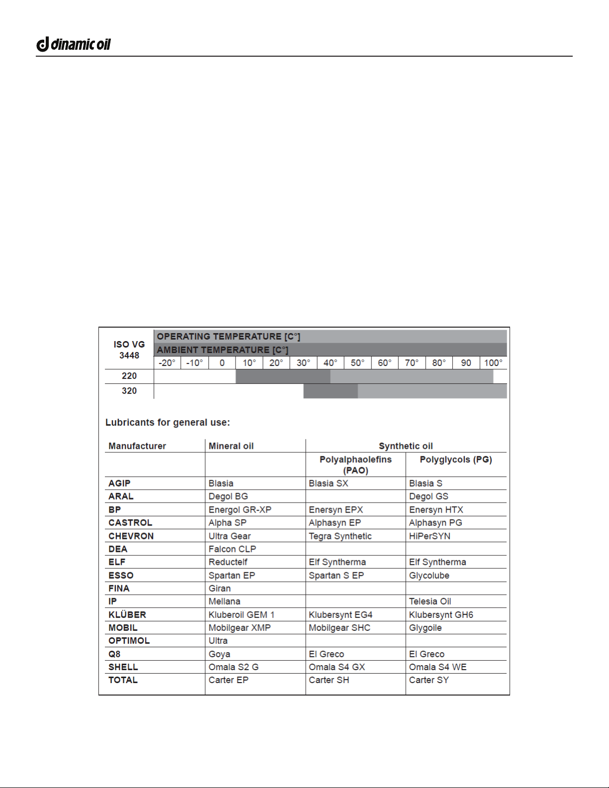
SELECTING AN OIL
Any mechanical transmission oil with EP additives in viscosity classes ISO VG220 to ISO VG320 under ISO 3448 can be
used. In special cases oils with dierent viscosities may be used. In this case, contact DInamic Oil technical assistance
service. The oil viscosity must be chosen to suit the room temperature and the gearbox’s real operating temperature. If
the gearboxes must operate at very high ambient temperatures or with very large temperature excursions, synthetic oil is
recommended.
RECOMMENDED VISCOSITY

17
Gearboxes - Hoists - Winches - Construction Attachments
SA Series Users Manual . Release 01 . English
DO NOT Exceed Maximum Oil Temperatures. Hydraulic Fluid and Gearbox Oil should not exceed:
Min Temperature = -4 F (-20 C)
Min Temperature = 194 F (90 C)
Exceeding these temperatures lowers the oil viscosity, which will lead to premature wear in the gears and seals in the
hydraulic motor and gearbox.
OPERATING TEMPERATURE PARAMETERS
In order for the Drive attachment to operate at peak performance the following guidelines must be followed to avoid damage
to the main components.
DO NOT exceed the advertise maximum hydraulic pressure.
DO NOT exceed the published maximum hydraulic ow.
Approved Operating Temperature Ranges F (C):
Hydraulic Motor/Manifold: -20 to 194 F (xx to 90 C)
Pressure Transducers: -40 to 250 F (-40 to 125 C)
TD Flange (Energi models): -4 to 194 F (-20 to 90 C)
WiFi Module (Energi models): -4 to 140 F (-20 to 60 C)
Gearbox: -4 to 194 F (-20 to 90 C)
F(C) -40 (-40) -20 (-29) 0(-17) 20 (-6) 40 (4) 60 (15) 80 (26) 100 (38) 120 (49) 140 (60)
Gearbox
CAUTION
Approved Temperature Ranges
Pressure Transducers
TD Flange
WiFi Module
Hydraulic Motor

18 SA Series Users Manual . Release 01 . English
Gearboxes - Hoists - Winches - Construction Attachments
OIL FILLING AND LEVEL CHECKING
Every gearbox is equipped with level, vent, lling and
draining caps for gear oil. The lubricating oil level is
located on the “top” section of the gearbox, to ensure the
upper bearing is lubricated.
OIL REPLACEMENT AND FILLING PROCEDURE
• Ensure the power supply is disconnected when
lling.
• Unscrew and remove the loading and level plugs.
• Place a receptacle of sucient size underneath the
draining cap.
• Unscrew the gearbox’s loading and draining caps
and allow the oil to completely drain.
• Replace the oil drain plug.
• Feed the oil through the lling port at the top of the
gearbox until it ows out of the level port.
• Ret the plugs using the appropriate tightening
torques.
• Unscrew the plug adjacent the lling port, located
on the upper part of the gearbox, to prevent an air
bubble from forming at the upper rotary seal.
AMOUNT OF OIL
Gear oil amounts are given on pages 12 and 13 of
this manual. The data sheets show the quantities of oil
required for lling. However, these values should be
used for reference purposes only and exact lubrication
should be veried by means of visual checks.
SUPPORT AND SERVICING
Servicing must be performed by authorized personnel
adhering to the work and environmental safety
standards. Servicing on the gearbox must be
performed with the power supply disconnected and
the gearbox taken “out of service” to prevent an
accident. The oil temperature must be at a safe level
so as not to burn the operators. The instructions given
in this paragraph must be followed, ensuring the gearbox
is operational and that required levels of safety are met:
• Only use original spare parts.
• Use lubricants that are recommended by the
manufacturer.
• After any servicing work, always replace the seal
washers and any lubricating oil.
• Use additional lighting if carrying out servicing work
in dimly lit areas, to ensure that it is performed
safely.
• Take relevant precautions if carrying out servicing
work in enclosed spaces, to ensure that it is
performed safely.
ROUTINE SERVICING
Proper servicing improves performance, longevity and
safety.
Check the gearbox oil level before each operation to
ensure the planetary is suciently lubricated.
After the rst 50 hours of operation:
• Check the gearbox oil level. Check for leaks.
• Change the gearbox oil - this is required as the rst
50 hours are considered the break-in period.
Important! If the rst oil change is not performed
after the rst 50 hours excessive gearbox wear can
occur and cause failure.
After the rst 150 hours of operation:
• Check the gearbox oil level. Check for leaks.
• Check there are no metal residues of abnormal size
in the magnetic caps on the gearboxes.
• Clean the surfaces of the hydraulic motor and
gearbox body and the air ventilation pathways.
• Change the lubricating oil.
• Check the screws are all tight, and tighten them
where required.
After every 3 months of operation and for the entire
service life of the gearbox, it is necessary to check:
• Check the gearbox oil level. Check for leaks.
• Check for contamination from dirt, metal residues
and other contaminants and deposits of water or
other contaminating liquids in the areas of the input
or output shafts, in particular close to the seals.
• Absence of oxidation on the input and output shafts
and near the sealing areas.
• Absence of abnormal clearance on the output/input
shafts, pinions, joints and other accessories.
• Absence of contact wear on input/output shafts,
joints, and other accessories; absence of cracks and
damage on supports, shaft anges, and other parts
of the gearbox.
• No breakage or extension of the ange and bolts.
• Check for any damage and vibrations or abnormal
noise.
• Be aware of any abnormal heating or abnormal
temperatures.
After every 2000 hours of operation or at least every
12 months:
• Clean the surfaces of the gearbox body and the
air ventilation pathways to ensure correct heat
dispersal.
• Check the screws are all tight, and tighten them
where required.

19
Gearboxes - Hoists - Winches - Construction Attachments
SA Series Users Manual . Release 01 . English
TORQUE CHART FOR COMMON FASTENERS
The chart below lists the correct tightening torque for fasteners. When bolts are to be tightened or replaced, refer to this
chart to determine the grade of the bolt and the proper torque. Except when specic torque values are list in a particular
application.
tpi = Nominal thread diameter in inches per inch.
Nm = Newton Meters.
Ft-Lbs = Foot Pounds
mm x = Nominal thread diameter in millimeters x thread pitch.
Bolt Size (In) Grade 2 Grade 5 Grade 8 Bolt Size (mm) Class 5.8 Class 8.8 Class 10.9
tpi Nm Ft-Lbs Nm Ft-Lbs Nm Ft-Lbs mm x Nm Ft-Lbs Nm Ft-Lbs Nm Ft-Lbs
1/4”-20 7.4 5.6 11 8 16 12 M5 X 0.8 4 3 6 5 9 7
1/4”-28 8.5 6 13 10 18 14 M6 X 1 7 5 11 8 15 11
5/16”-18 15 11 24 17 33 25 M8 X 1.25 17 12 26 19 36 27
5/16”-24 17 13 26 19 37 27 M8 X 1 18 13 28 21 39 29
3/8”-16 27 20 42 31 59 44 M10 X 1.5 33 24 52 39 72 53
3/8”-24 31 22 47 35 67 49 M10 X 0.75 39 29 61 45 85 62
7/16”-14 43 32 67 49 95 70 M12 X 1.75 58 42 91 67 125 93
7/16”-20 49 36 75 55 105 78 M12 X 1.5 60 44 95 70 130 97
1/2”-13 66 49 105 76 145 105 M12 X 1 90 66 105 77 145 105
1/2”-20 75 55 115 85 165 120 M14 X 2 92 68 145 105 200 150
9/16”-12 95 70 150 110 210 155 M14 X 1.5 99 73 155 115 215 160
9/16”-18 105 79 165 120 235 170 M16 X 2 145 105 225 165 315 230
5/8”-11 130 97 205 150 285 210 M16 X 1.5 155 115 240 180 335 245
5/8”-18 150 110 230 170 325 240 M18 X 2.5 195 145 310 230 405 300
3/4”-10 235 170 360 265 510 375 M18 X 1.5 220 165 350 260 485 355
3/4”-16 260 190 405 295 570 420 M20 X 2.5 280 205 440 325 610 450
7/8”-9 225 165 585 430 820 605 M20 X 1.5 310 230 650 480 900 665
7/8”-14 250 185 640 475 905 670 M24 X 3 480 355 760 560 1050 780
1”-8 340 250 875 645 1230 910 M24 X 2 525 390 830 610 1150 845
1”-12 370 275 955 705 1350 995 M30 X 3.5 960 705 1510 1120 2100 1550
1-1/8”-7 480 355 1080 795 1750 1290 M30 X 2 1060 785 1680 1240 2320 1710
1-1/8”-12 540 395 1210 890 1960 1440 M36 X 3.5 1730 1270 2650 1950 3660 2700
1-1/4”-7 680 500 1520 1120 2460 1820 M36 X 2 1880 1380 2960 2190 4100 3220
1-1/4”-12 750 555 1680 1240 2730 2010
1-3/8”-6 890 655 1990 1470 3230 2380
1-3/8”-12 1010 745 2270 1670 3680 2710
1-1/2”-6 1180 870 2640 1950 4290 3160
1-1/2”-12 1330 980 2970 2190 4820 3560

20 SA Series Users Manual . Release 01 . English
Gearboxes - Hoists - Winches - Construction Attachments
WARRANTY INFORMATION
Dinamic Oil North America (DONA) warrants its gearbox for a period of twenty-four (24) months and twelve (12) months on
the hydraulic motor months from invoice date to the original user.
DONA warranty covers faulty workmanship and defective parts manufactured by DONA. The warranty does not extend
to transportation cost of parts, nor does it cover consequential loss or damage to prime mover equipment. Dinamic Oil
Construction Attachments must be operated in accordance with the recommended procedures and within the specied
operating parameters, both on the unit and contained in the operating manual. DONA will not be responsible for or accept
any charges for work carried out by any repairs, or for any charges for any spare parts tted to any DONA products without
written approval from DONA. This warranty is void if eld repairs have been made to the hydraulic motors, gearboxes and
controls without written approval. The complete unit must be available for inspection in its original but alleged failed condition.
Dinamic Oil North America reserves the right to make design, specication and price changes without notice, and obligations
to the eect of such changes.
LIMITATION OF LIABILITY - DONA takes no responsibility for Goods selection, operation, and use, regardless of any
recommendations or suggestions made by the DONA. Buyer shall make selections based upon its own analysis with regard
to function, material compatibility, tness for use or intended purpose, and Goods ratings. Any such analysis, including
testing, shall be the sole responsibility of Buyer. Proper installation, operation, and maintenance are solely the responsibility
of Buyer or its customer. Any specications listed in DONA’s datasheets, catalog, and website are for reference only and are
subject to change without notice.
RETURNED GOODS (RGA)
Dinamic Oil reserves the right to determine whether products claimed to be defective shall be inspected by our personnel
in the eld or returned to the factory. If determined to be defective in material or workmanship, the product will be
replaced or a credit issued at the option of Dinamic Oil North America.
All returns for replacement or credit MUST be accompanied by a RGA number. Products returned without an RGA
number will be rejected and returned to the sender freight collect. All returns must be shipped “prepaid”. Products
shipped “collect” will be refused. Proof of purchase such as invoice number must accompany returns. All RGA’s must be
returned within 30 days of the request.
PARTS / SERVICE
Minimize downtime and maintain peak performance by choosing genuine Dinamic Oil parts and maintenance kits for your
gear products. For assistance, please contact us:
EMAIL: [email protected]
PHONE: 1.704.587.4600
This manual suits for next models
9
Table of contents
Other DINAMIC OIL DC Drive manuals

Popular DC Drive manuals by other brands

HAUTAU
HAUTAU SM 101 Installation and operating instructions

easydriver
easydriver basic 1.8 Installation and instruction manual

Ingersoll-Rand
Ingersoll-Rand TRANE AFDJ Installation, operation and maintenance

Raymarine
Raymarine E12026 installation guide

YASKAWA
YASKAWA SI-P1/ V7 instructions

Becker
Becker M installation manual


