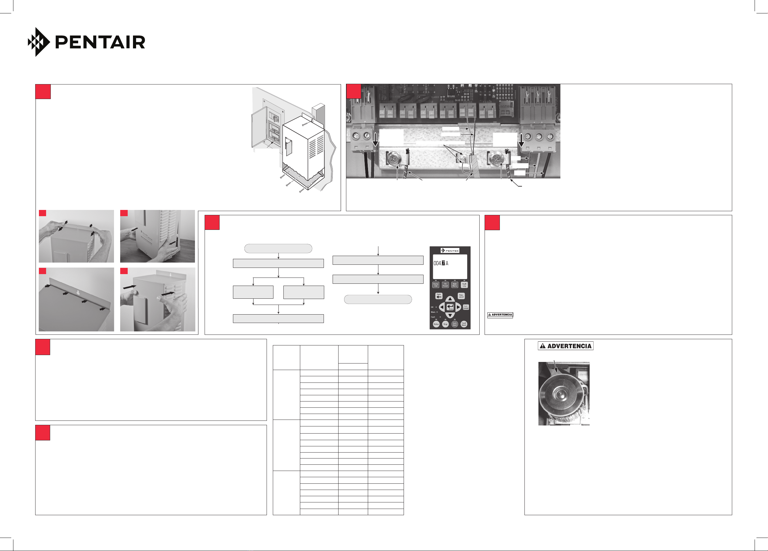
Borne
removible
(jalar hacia
abajo)
01+ 01+ I1+ I1- I2+ I2- V+ V- AI+ AI- P N SD CARD
Conexiones del cable
del transductor
Motor sumergible: Trifásico/Trifilar. Monofásico siga los colores indicados arriba.
Motor sumergible: Monofásico/Bifilar, conecte a Y y B, en cualquier orden.
Motores sobre la superficie: L1 a R, L2 a Y, L3 a B; verificar la rotación
Tornillo a tierra
de salida
Conexiones de
energía de entrada
Tornillo a tierra
de entrada
Rojo
Amarillo
Negro
Tierra de salida
Tierra de
entrada
Conexiones del motor
Rojo a AI+
Negro a AI–
Tornillo/escudo del cable verde
Borne
amovible
(en tirant)
Cuadro 1: PENTEK®Amperios del Factor de Servicio
Tipo de
motor
Número de pieza
PENTEK
Clasificación
nominal
@ 230V
Factor de
servicio
Amperios
HP
Bifilar (2)
P42B0005A2-01 1/2 4.7
P42B0007A2-01 3/4 6.2
P42B0010A2-01 1 8.1
P42B0015A2-01 1-1/2 10.4
P42B0005A2-02 1/2 5.1
P42B0007A2-02 3/4 6.1
P42B0010A2-02 1 8.0
P42B0015A2-02 1 1/2 10.6
CS/CR
Trifilar (3)
P43B0005A2-01 1/2 4.8
P43B0007A2-01 3/4 6.0
P43B0010A2-01 1 7.3
P43B0015A2-01 1-1/2 10.9
P43B0005A2-02 1/2 4.5
P43B0007A2-02 3/4 5.7
P43B0010A2-02 1 6.8
P43B0015A2-02 1 1/2 10.7
Trifásico (3)
P43B0005A3 1/2 2.9
P43B0007A3 3/4 3.9
P43B0010A3 1 4.7
P43B0015A3 1-1/2 6.1
P43B0020A3 2 7.6
P43B0030A3 3 10.1
P43B0050A3 5 17.5
Arranque Inicial: Incio del Sistema
• Abrir las llaves en los extremos de las tuberías para dejar escapar el aire durante la
presurización. Oprimir “Auto Start” (Inicio automático).
• ElMecanismodeAccionamientopasaráa“AutoLineFill”(Llenadodetuberíaautomático).
• Cerrar las llaves en los extremos de las tuberías después de haber dejado escapar todo el
aire.
• Cuando el Transductor detecte 10 PSI, el Mecanismo de Accionamiento pasará al Modo
de Presión Constante y mantendrá las 60 PSI.
• Si se requiere una presión diferente, utilice PSI Preset para cambiar el punto de
referencia.
6
Arranque Inicial: Bombear Para Vaciar el Pozo
Dirigir la descarga de la bomba hacia un lugar adecuado que no esté conectado al sistema. Oprimir
“Pump Out” (Vaciar por bombeo). La bomba funcionará a 45 Hz. Ajuste de frecuencia según sea
apropiado:
A. Oprimir “Enter.”
B. Cambiar el valor de frecuencia.
AVISO Las instalaciones sobre el suelo requieren una operación de 60 Hz para cebar. Después
de haber cebado, ajuste la frecuencia como corresponda.
C. Oprimir “Enter” nuevamente. Activar el Mecanismo de Accionamiento en este modo hasta que la
descarga del pozo sea clara y transparente, luego oprimir “STOP” para detener el Mecanismo de
Accionamiento.
Peligro de explosión. Puede provocar lesiones graves, daños materiales o muerte. En
el modo Vaciar por Bombeo, la bomba marcha a una velocidad constante. Una restricción de flujo
puede provocar una presión muy alta. No se debe restringir el flujo.
4
Conexiones de los cables
A. Desconectar la alimentación a la caja del disyuntor antes de
realizar las conexiones.
B. Conectar PRIMERO el cable del motor, SEGUNDO, el cable
del transductor, y POR ÚLTIMO, los cables de alimentación.
Inspeccionar el interior del Mecanismo de Accionamiento.
Verificar que no tenga cables sueltos ni suciedad antes de
cerrarlo.
C. Volver a colocar la cubierta y fijarla con el tornillo de la
cubierta antes de conectar el cable de alimentación de
entrada a la caja del disyuntor.
AVISO Cuando se use un motor sobre tierra clasificado para
usar con el PENTEK INTELLIDRIVE, la longitud máxima del cable
conductor debe ser de 25 pies (7.62 m). Consultar el manual del
usuario específico del motor y las normas de Código Nacional de
Electricidad (NEC) para determinar el tamaño del cable.
alta cuando la bomba está en marcha.
• Es necesario desconectar la
alimentación y esperar 5 minutos
antes de abrir y sacar la cubierta del
Mecanismo de Accionamiento.
• Se debe montar el Mecanismo de
Accionamiento en un perno o poste
ANTES de realizar las conexiones
eléctricas.
• No se debe tocar el Mecanismo de
Accionamiento con manos húmedas o
mojadas.
• Se debe desconectar la alimentación y
sacar la cubierta con manos secas.
Peligro de incendio. Si se instala con
protección de un disyuntor incorrecto. El
Mecanismo de Accionamiento se debe
instalar en un ramal independiente, sin
ningún otro aparato electrodoméstico
conectado al circuito y debe estar
protegido por un disyuntor, tal como se
especifica en el Manual del Propietario.
Procedimiento de instalación del Mecanismo de Accionamiento
• Comenzar el procedimiento con la remoción del tornillo en la parte inferior de la cubierta
delantera.
• Jalardelapartesuperiordelacubiertahaciausted(Fig.1a),alejándoladelaplacaposterior
paracrearunespacio(Fig.1b).
• Jalardelaparteinferiordelacubiertahaciausted(Fig.1c);levantarysacarlacubierta.
• Montar el Mecanismo de Accionamiento en posición vertical en un perno, poste o sobre una
superficie plana.
• FijarelMecanismodeAccionamientoenformapermanenteusandoelorificiosuperior
ranurado, y ya sean los tres orificios inferiores (para el montaje sobre una superficie plana)
o el orificio central inferior (para el montaje sobre un poste o perno).
• Dejar un espacio libre de 3 pulgadas (7.62 cm) alrededor del Mecanismo de Accionamiento
para proporcionar un enfriamiento adecuado.
1
Disyuntor
típico de
230 voltios
(doble
ancho)
Filtro EMI/RFI
Peligro de choque eléctrico. Puede
provocar choques, quemaduras
o muerte. Se debe estar atento a
riesgos tales como:
• Los componentes internos del
Mecanismo de Accionamiento
retienen una tensión alta hasta
5 minutos después de haber
desconectado la alimentación de
entrada.
• ElFiltroEMI/RFItieneunatensión
Arranque Inicial: Programar el Mecanismo de Accionamiento
Aplicar una potencia de 230V al PENTEK INTELLIDRIVE. “Setup Guide” (Guía de Configuración)
aparecerá en la pantalla. Oprimir las teclas en el orden indicado aquí:
3
Setup Guide 12:10p
Service Factor Amps
Stopped
Arranque Inicial: Lista de Verificación
•Verificar que el sistema tenga una válvula de desahogo y un tanque a presión del
tamaño adecuado.
• Verificar que la precarga del tanque a presión sea un 70 por ciento de la presión de
referencia del unidad (42 PSI (libras por pulgada cuadrada) para el punto de referencia
predeterminado de 60 PSI).
• Verificar que la descarga de la bomba esté conectada al sistema.
• Verificar que los cables a tierra de entrada, de salida y del blindaje del transductor estén
debidamente conectados.
5
(Continúa en la columna siguiente)
AVISO Los amperios indicados en la
placa de fábrica pueden ser diferentes de
estos valores. Para los motores PENTEK,
use los valores indicados aquí.
En usos de readaptación sumergible con
motores trifilares, monofásicos de otros
fabricantes, se deben usar los valores de
arranque y marcha del capacitor (Cap Start/
Cap Run) suministrados por el fabricante
del motor. Para motores trifásicos, se debe
usar el amperaje del factor de servicio
indicados por el fabricante del motor.
Para motores sobre tierra, se debe usar el
valor de amperios más alto indicado (puede
estar indicado como “amperios de carga
máx” o como “amperios a plena carga”).
AVISO Consultar el Manual del Propietario
para obtener más ilustraciones e
información detallada.
Para obtener asistencia, llamar
al Departamento de Atención al
Cliente de PENTEK 1-866-9PENTEK
(973-6835)
2
AVISO Después de haber completado todas las conexiones de los cables en el Paso 2,
volver a fijar la cubierta enganchándola en la parte superior de la placa posterior (es
importante dejar un espacio). Bajar y colocar la parte inferior de la cubierta en posición.
Empujarlacubiertauniformementecontralaplacaposterior(Fig.1d),eliminandoel
espacio. Volver a colocar el tornillo en la parte inferior de la cubierta delantera.
1a
1b
1c
1d
Pulse “Enter” (Ingresar)
Pulse “Enter” (Ingresar)
Pulse “Enter” (Ingresar)
Pulse “Enter” (Ingresar)
Pulse “Enter” (Ingresar)
Aplique 230 V al Mecanismo
Configure la hora
Configure la fecha
Configuración completa
Tipo de conexión
[bifilar (2) o trifilar (3)]
Tipo de Motor
Sumerg. o sobre sup.
Ingrese amperaje de factor de servicio
Ingrese fase del motor [monofásico (1) o trifásico (3)]
6566 0512 SP
Monofásico (1) Trifásico (3)
Pulse “Enter” (Ingresar)
Pulse “Enter” (Ingresar)
Pulse “Enter” (Ingresar)
Pulse “Enter” (Ingresar)
Pulse “Enter” (Ingresar)
Aplique 230 V al Mecanismo
Configure la hora
Configure la fecha
Configuración completa
Tipo de conexión
[bifilar (2) o trifilar (3)]
Tipo de Motor
Sumerg. o sobre sup.
Ingrese amperaje de factor de servicio
Ingrese fase del motor [monofásico (1) o trifásico (3)]
6566 0512 SP
Monofásico (1) Trifásico (3)
Guía Básica de Inicio
Consultar el Manual del Propietario para obtener información sobre la instalación, el funcionamiento y la seguridad.
Esta guía no suplementa ni sustituye el Manual del Propietario.
PENTEK
INTELLIDRIVETM


