Dinel PCU-100 Series User manual

Before the rst use of the unit, read the instructions in this manual and keep it
carefully. The manufacturer reserves the right to do alteration without prior notice.
PROGRAMMABLE CONTROL UNIT
PCU–100
USER MANUAL
Firmware version 2.0.2. or higher


1 . Basic description ................................................................................................................... 4
2 . Range of application .............................................................................................................. 5
3 . Variants of sensors ................................................................................................................ 5
4 . Dimensional drawings ........................................................................................................... 5
5 . The front panel and terminal block ........................................................................................ 6
6 . Installation and putting into operation ................................................................................... 6
7 . Mechanical mounting ............................................................................................................ 6
8 . Electrical connection ............................................................................................................. 7
9 . Settings ................................................................................................................................ 10
9.1. Setting of the input channel in the unit .......................................................................... 11
9.2. Display conguration .................................................................................................... 16
9.3. Conversion Rules ......................................................................................................... 19
9.4. Output Relay .................................................................................................................25
9.5. The archiving and data export conguration ............................................................... 27
9.6. Parametrization of connected measuring devices using the HART® protocol .............. 28
9.7. Other settings of the control unit .................................................................................... 37
9.8. Menu Structure ............................................................................................................. 40
10 . Functions of the device ......................................................................................................44
10.1. Description of the front panel ......................................................................................44
10.2. Signalling functions ....................................................................................................45
10.3. Export of data .............................................................................................................45
10.4. Displaying Functions of the User Menu .....................................................................46
10.5. Unit rmware updates ................................................................................................. 47
11 . Order code .........................................................................................................................48
12 . Correct specication examples ......................................................................................... 49
13 . Safety, protection and compatibility ................................................................................... 49
14 . Use, manipulation and maintenance ................................................................................. 49
15 . General, conditions and warranty ..................................................................................... 50
16 . Marking of labels ................................................................................................................ 50
17 . Technical specications ..................................................................................................... 51
18 . Packing, shipping and storage ........................................................................................... 52
CONTENT

PCU–100 © Dinel, s.r.o.
4
Programmable control unit PCU–100 is used for measurement, displaying and archiving of the
physical value (liquid level, pressure, ow, temperature, etc.). One transducer of physical magni-
tude with an analogue 4-20 mA output can be connected to the unit.
Dierent types of conversion (converting) characteristics (linear, square, root and user dened),
may be selected, also the tank dimensions for conversion to the volume of the media may be speci-
ed. The unit is also available in the version without graphic LCD display that is replaced with the
status LEDs. The unit has a battery backed real-time circuit. Archiving with user-dened period
takes place on the internal ash memory with a capacity sucient for more than 500,000 samples.
Data can be exported to a micro SD card for additional processing.
User conguration is possible through a regular desktop application after connecting a PC via
a micro USB connector located on the front panel of the unit. For the version tted with an LCD
display the conguration is also possible using the graphical menu and four membrane keys.
The unit is equipped with one input settings in the hardware conguration according to the type of
unit. One relay output is fully user-congurable, including the possibility of two-state control. The
functionality of the unit is expandable with optional modules. The units are built into the ABS / PC
instrument boxes intended for wall mounting. Connection terminal is located inside the device.
All the operations described in these operating instructions must be made only by trained
personnel or by an authorised person. Warranty and post-warranty repairs must be carried
out exclusively at the manufacturer. Incorrect sensor use, assembly or conguration may
cause accidents in the application (tank overlling or damage to the system components).
The manufacturer is not responsible for the improper use, working losses incurred by
either direct or indirect damage and the expenditure incurred during the installation or
the use of the sensor.
In order to ensure maximum safety of control processes, we have dened the following safety and infor-
mation instructions. Each instruction is marked with a corresponding pictogram.
Caution, warning, danger
This symbol informs about particularly important instructions for the installation and opera-
tion of the device or dangerous situations that may occur during installation and operation.
Ignoring these instructions may be the cause of the fault, damage to or destruction of the
device or may cause damage to health.
Information
This symbol indicates particularly important device characteristics and recommendations.
Note
This symbol indicates the useful additional information.

5
© Dinel, s.r.o. PCU–100
Programmable control unit can be used as a universal industrial data logger for monitoring of
a measured value. Thanks to a relay output, it is also possible to use the unit for the control of
the process of measured value using two-state control.
• PCU–100–D Front panel with a graphic LCD display and a membrane keypad. The en-
try depending on conguration (for connecting one sensor), one relay output.
The unit is available in two versions. The makes are dierent by the front panel appearance.
Both versions have a micro USB connector to connect a computer to congure the unit via the
conguration application and micro SD card slot for the purposes of exports of the recorded data.
• PCU–100–L The front panel without an LCD display with status LEDs. The entry
depending on conguration (for connecting one sensor), one relay output
the earthing contact

PCU–100 © Dinel, s.r.o.
6
• A number of evaluation units PCU-100-_ is designed to be installed on a wall using four mounting
screws or bolts (hereinafter referred to as “the screws”).
• When installing the device, it is rst necessary to withdraw the transparent polycarbonate hous-
ing of the front panel that is held in place by 4 plastic screws. The mounting holes designed for
screws for attaching to the wall are located under the plastic screws. Using the screws, the unit is
xed in the required position on the wall. Now, it is possible to connect the cables to the terminals.
• Then, return the transparent cover to the place on the front panel and its plastic screws are suf-
ciently tightened to achieve full coverage.
• The prescribed tightening torque is 3 Nm.
No. of terminal
1L (85 - 253 VAC)
2N (85 - 253 VAC)
3 Functional earthing
4Current input +
5Current input -
20 RE 1 (100 mA / 250 VAC)
21 RE 1 (100 mA / 250 VAC)
SCHÉMA ŠTÍTKU (ČERVENĚ JSOU VYZNAČENY OTVORY)
Poznámka: šedé orámování tlačítek bude ještě v rovině fólie
www.dinel.cz
Programmable Control Unit PCU-100
ESC OK
1234
PIN 1
PIN 1
1234
MAR SR 191
Transparent
PANT 320
vývod
z rubové
strany
PIN 1
14,5
15
SCHÉMA ŠTÍTKU (ČERVENĚ JSOU VYZNAČENY OTVORY)
MAR SR 191
PANT 320
www.dinel.cz
Programmable Control Unit
PCU-100
POWER
POWER
SD CARD
LOGGING
OUTPUT
POWER
PCU–100–D PCU–100–L
Terminal Block: PCU–100–_–I:
This procedure has the following three steps:
•
•
•
Be extremely careful when placing the cover in place. It is not possible to settle the front
cover arbitrarily, there are located protrusions on the bottom of the housing and on the body
of the boxes. At bad settlement, these protrusions may prevent the full engagement of the
seal and the achievement of full coverage.

7
© Dinel, s.r.o. PCU–100
Electrical connection can only be made in a voltage-free state!
The temperature of the internal components of the unit may under specic conditions exceed
a temperature of 60°C after a longer period of time in service. Take care when handling.
• The device may only be connected to the power supply via an easy to reach switch with
marked turned o/on positions and must be protected by a fuse or circuit breaker with a value
of max. 16 A!
• The used connecting cables must be of circular cross-section of the prescribed diameter (2.5 - 6.5
mm). The connection cable must be according to the specications of the manufacturer rated to
the operating voltage (85 - 253 VAC) and the current load corresponding to the rated wattage (6
VA) at this voltage. The insulation material must comply with the operating voltage and endure the
ambient temperatures of up to 70 °C. In the case, there is no cable in the penetration, the penetra-
tion must be tted with a plug. Cable grommets must be tightened to the specied torque (3 Nm).
The switch or circuit breaker used as the disconnect device must be in accordance with the
IEC60947-1 and IEC60947-3, must be marked and must not be in the network inlet.
The external power supply is not connected
Power supply inlet power supply AC lead “L” to the terminal No.1 and lead “N” to the
terminal No.2.
Connections of input device current loop “+” to terminal No. 4 and “-” to No. 5
Relay output (galvanically sepa-
rated solid state relay - SSR) the connection to the terminals No.6 and No.7.
The electrical connection is made to the terminal block of the device. For an access to the terminal
block, it is required:
1. Remove the transparent front polycarbonate housing (see chapter Mechanical assembly)
2. Grip the front panel on the sides by the grips intended for this purpose (see gure below)
3. Pull evenly on both sides to eject the front panel from the connector.
PCU–100 © Dinel, s.r.o.
8
The grounding wire is always attached only in one place by using the method 1 or 2. It is
never attached in both places at the same time.
Grounding wire connected to the unit serves always as the functional ground to improve the as-
sembly resistance against EM interference and does not full the protective function. Connection
of a functional earth to the unit is possible in one of the two ways while we are choosing the way
that allows connection the ground wire on a shorter route:
1. We will connect the grounding wire inside the unit to the terminal number three where it is as-
sumed to bring the earthing wire to the unit within the power cable.
2. The grounding wire will be connected to the external earth terminal of the device, which is
located on the bottom of the box together with outlets.
*
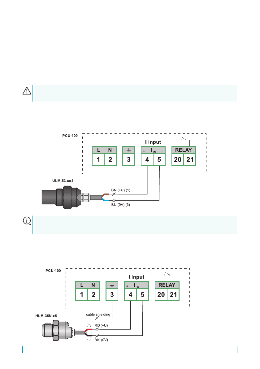
Example connection:
A n ex am pl e of the PCU –10 0 - _- I uni t c on ne ct io n w it h t he leve l s en so r U LM - 53 - _ _ - I is shown here.
Legend:
BN – brown
BU – blue
The level transmitter ULM-53-__-I may be replaced by any other measuring device
with current output.
(RD (+U)(1))
(BK (0V)(3))
Legend:
RD – red
BK – black
---- – shielding
Example of a circuit with shielded cable:
A n ex am p le of t he PC U –1 0 0 - _ - I u ni t c o nn ec t io n w it h t h e l ev el se ns o r - H LM - 3 5 N - _ K is sh ow n h er e.

9
© Dinel, s.r.o. PCU–100
The example of several level meters connection with the HART®protocol support:
The example of the PCU-100-_-H unit connection with several ULM-70-N-_ _-_-I level meters is
shown here.
It is important that the measuring devices are in the so-called multi drop mode. For level meters from
Dinel s.r.o., this mode is set by changing the HART® polling address to other than 0. Regardless of
the measured value, a constant current of 4 mA ows through the level meter and communication
then proceeds only via the HART® protocol.
The ULM-70N-_ _-_-I level meter can be replaced by any other mesuring device with current output
and the HART®protocol support (such as GRLM-70 or CLM-70 from Dinel s.r.o.). The devices can
also be combined and do not have to be of the same type.
For correct functionality it is also necessary that all connected devices have different polling
addresses (see chapter [reference to chapters 9.1.1 and 9.6.1]).
I Input
Legend:
BN – brown
BU – blue
(1...) – numbers of the
connector terminals

PCU–100 © Dinel, s.r.o.
10
Be extremely careful when placing the cover back in place. It is not possible to settle the
front cover arbitrarily, there are located protrusions on the bottom of the housing and on the
body of the boxes. At bad settlement, these protrusions may prevent the full engagement of
the seal and the achievement of full coverage.
The symbol used in the manual: [ESC]
Functionality:
• The procedure in the menu one level up
• Change cancelling when editing
The symbol used in the manual: [↕]
Functionality:
• The shift in the menu
• Increase of the highlighted character value on the screen for entering the values
The symbol used in the manual: [↔]
Functionality:
• The shift in the menu
• Shift between the characters on the screen for entering the values
• Change the value of the check mark at the menu item
• Change the value on the screen with the values selection
The symbol used in the manual: [OK]
Functionality:
• Entering the main menu
• Entering the sub-menu
• Conrming changes when editing
If no key is pressed within 5 minutes in the menu, the unit automatically switches back to the
display mode.
The basic functions of buttons and their symbols
The units in the version PCU–100-D with LCD display can be set using the graphical menu con-
trolled by four membrane keys. For access to the control buttons and USB connector, it is necessary
to withdraw rst the transparent polycarbonate housing of the front panel that is held in place by
4 plastic screws. (see Chapter Mechanical mounting).

11
© Dinel, s.r.o. PCU–100
The application is free to download at www.dinel.cz/download-1
Entry to the menu and scrolling through the menus
The entry to the menu is performed by pressing the [OK] button. By pressing briey the button [↕]
we are moving in the sub-menu, we get to the next level by pressing [OK]. The edited data can be
changed using the arrows [↕] [↔]. The changes are saved with the [OK] button, back to the main
menu, we get by pressing the button [ESC].
The unit can also be fully set up using a PC conguration application. To connect the unit to your
computer, a micro USB connector on the front panel of the unit is used. PCU-100-L units that are
not equipped with a display can only be parametrized using this application.
The layout of the application is intuitive and respects the layout of the graphical menu of the unit
(user manual). A more detailed description can be found in the user manual for the application.
The Micro USB cable must be connected to the unit on the y; it must not be connected
before connecting the unit to the power supply.
For a correct display of bar graph and for the purpose of the transfer characteristics conguration
it is necessary to specify the limits of the measuring range of the unit, thus, minimum value of the
input magnitude (corresponds to 0 %) and its maximum value (corresponds to 100 %).
The measuring range can be also congured inversely, when minimum of the range corresponds
to a greater level of the input value than the maximum of the range.
Deviation of values outside the measuring range is indicated on the display of the unit by the text
“Below the range”/”Above the range”. However, the conversion of the value for display and archiv-
ing takes place also within the limits of the extended measuring range, if congured. Outside the
extended measuring range is logged and displayed the value -N/A (below the minimum) or +N/A
(above the maximum).
The extended measuring range can be congured identically as the measuring range. In this way
the unit behaves even if the limits of the extended measuring range of the congured senselessly
(in the area of the measuring range or inverted).

PCU–100 © Dinel, s.r.o.
12
By factory default settings, HART®communication units (PCU-100-_-H-_-_) operate with an
analogue current value in the loop in mA (see chapter 9.1.3.). When the input is changed to a digital
value, the measuring range limits are entered in the relevant physical units. Which were set on the
measuring device.
Example:The levelmeter GRLM-70N-10-_-I-_-_-E2000 isconnected to theunit PCU-100-_-H-_-_.
In case that we want to read the distance digitally to the level in millimetres, we set the MIN RANGE
= 100 and MAX RANGE = 2000.
Range Minimum Range Maximum
0 % 100 %
-N/A Measuring range +N/A
Extended measuring range
Minimum of the Extended Range Maximum of the Extended Range
<0 % = Indication
“Below the range“
>100 % = Indication
“Above the range”
Type of unit
inlet
Measuring
range mini-
mum
Measuring
range maxi-
mum
Extended
measuring
range mini-
mum
Extended
measuring
range
maximum
Limits of the
user congu-
ration
Menu ID 028 029 030 031 –
Current 4 mA 20 mA 3.85 mA 20.55 mA 0 – 24 mA
HART®4 mA / [-] 20 mA / [-] 3,85 mA / [-] 20,55 mA / [-] neomezený
13
© Dinel, s.r.o. PCU–100
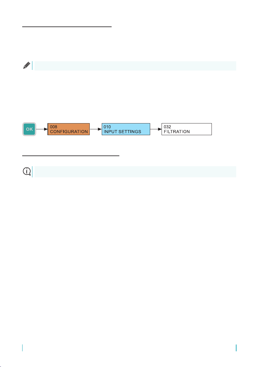
It is suitable to use the ltration function for suppression of the uctuations in view at fast or jump
changes of the input value. The subsequent speed of change of the input value will be depend-
ent on an exponential course. Filtration with dened delay in seconds indicates the time that the
exponential curve reaches 2/3 of its maximum value.
Control units with the HART® communication input (PCU-100-_-H-_-_) make it possible to work
with a current value in the loop measured analogously or a digital value of the measured quantity
read out using the HART® protocol. This communication is described in chapter (see chapter 9.6).
The following types of the input channel can be set for this unit:
• Menu:
• Default value: 20 sec
• Conguration range: 0-999 sec
• [↔] - Movement between the characters [↕] - Change of Value
• Analogue
The measured magnitude is read from the value of current in the current loop.
• HART®– primary variable
The measured magnitude is determined by the primary variable received
from the measuring device.
• HART®– secondary variable
The measured magnitude is determined by the secondary variable received
from the measuring device.
• HART®– tertiary variable
The measured magnitude is determined by the tertiary variable received
from the measuring device.
• HART®– quaternary variable
The measured magnitude the quaternary variable received
from the measuring device.
This setting is only available for units with the HART®input (PCU-100-_-H-_-_).
To turn off the ltration, it is necessary to congure the value to 0 seconds.
PCU–100 © Dinel, s.r.o.
14
If the control unit is required to read the input magnitude digitally using the HART® protocol, it
is necessary to check the conguration in which the PCU-100-H is connected to the other con-
nected devices. The following 2 states can occur:
1. The unit is connected only to measuring devices (ow meters, level meters, etc.)
and no other HART®communicator is connected to the network.
In this case, the unit should be set as the primary master.
2. The unit is connected to measuring devices (ow meters, level meters, etc.) and
another HART®communicator is connected to the network as well.
In this case, it is necessary to set the PCU to the opposite master type than the HART®
communicator. This means that if the connected HART® communicator is set as the prima-
ry master, the PCU must be set as the secondary master and vice versa.
Primary and secondary masters are terms dened in the HART®protocol standard. These are the
devices that initiate communication with measuring devices. They actively query by commands
and process the responses from measuring devices. The PCU-100-H unit is always in the master
(primary or secondary) position, while the measuring devices are always in the slave position.
• Menu: (
• Default: Primary
• [↔] - The type selection of the master
008
CONFIGURATION
010
INPUT SETTINGS
055
MASTER TYPE
Primary, secondary, tertiary and quaternary variables are terms dened in the HART®protocol
standard. Their values depend on the type of connected level meter. For ULM-54, ULM-70,
GRLM-70, and CLM-70 level meters from Dinel s.r.o., the individual variables are described in
chapter.
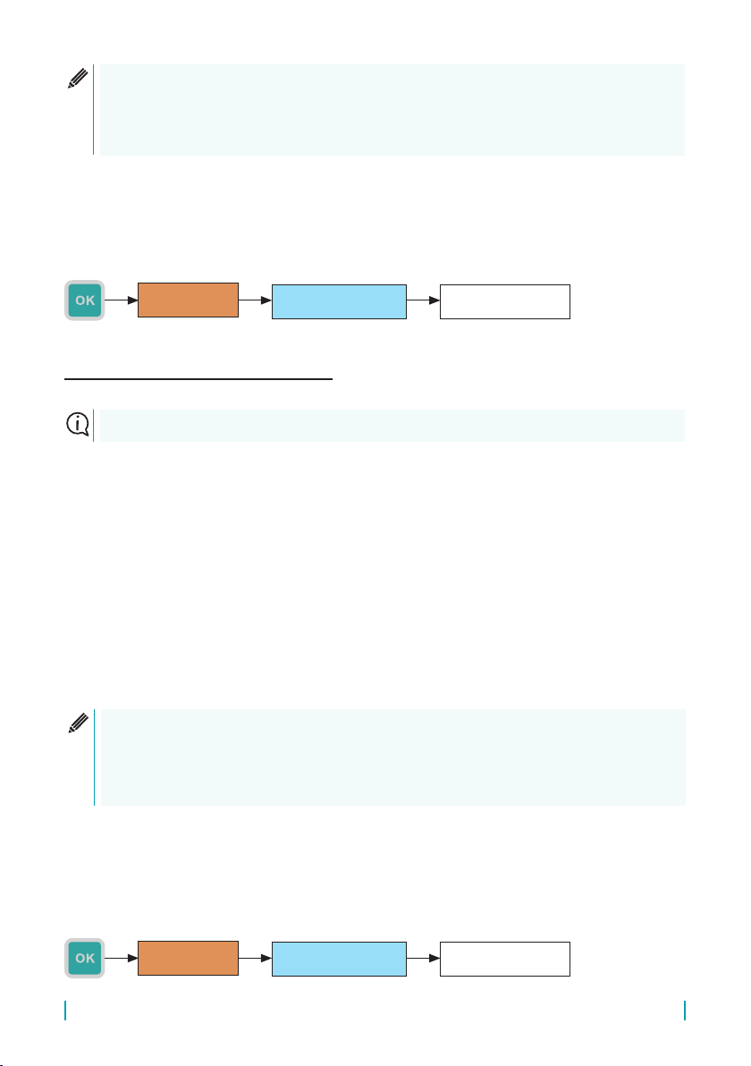
• Menu: (
• Default: Analogue
• [↔] - Selection of the measurement input source
008
CONFIGURATION
010
INPUT SETTINGS
054
INPUT TYPE
This setting is only available for units with the HART®input (PCU-100-_-H-_-_).
®

15
© Dinel, s.r.o. PCU–100
By factory default settings, the polling address of the sensor with the HART® protocol support
is set to 0. This setting is intended for the operation of the only sensor connected to the input of
the unit (or any other master device in general). All digital communication then proceeds with this
only sensor and the sensor also sets the loop current to its full extent depending on the measured
quantity.
If several sensors are required to be connected to the unit (or any other master device in general),
then these sensors must have polling addresses set in the range 1–15. In this setting, the sensor
communicates just at this address, the current in the loop is xed to 4 mA and the measured value
is read only digitally using the HART® protocol.
By setting the device’s polling address to the unit, you specify the sensor with which the device
should communicate. The sensor with the relevant polling address can then be parametrized
(procedure in chapter 9.6.) or the digitally measured value can be read from it, see chapter 9.1.3.
This setting is only available for units with the HART®input (PCU-100-_-H-_-_).
Each of the connected devices must have a unique polling address
• Menu: (
• Default: 0
• Conguration range: 0-15
• [↕] - Value change
008
CONFIGURATION
010
INPUT SETTINGS
056
DEVICE ADDRESS

PCU–100 © Dinel, s.r.o.
16
The conguration of the main screen graphical style showing the measured value according to the
user conguration. The conguration will aect the size of the digits, possible display of the bar
graph, date and time. Detailed view is intended more as a diagnostic and, therefore, it shows the
value of the input as well as user value with a xed number of decimals.
• Menu: Main screen type (ID 020)
• Default: Basic 32 px
• [↔] - Change the display type
Basic 32 px With bar graph 24 px
Detailed 8 px
The conguration of a preferred number of decimal places on the main screen. The display takes
place with a specied number of decimal places, if the amount of the value of the to display allows
it with regard to the number of positions on the display. If there is not enough positions available
for display, automatic reduction of the number of decimal places takes place.
The detailed display mode works with a xed number of decimals and this conguration is not
reected.
• Menu: DECIMAL PLACES ID (021)
• Default value: 2
• Conguration range: 0-5
• [↕] - Change of value

17
© Dinel, s.r.o. PCU–100
unit
The physical unit for display on the main screen, the unit is not stored into the memory, to the head
of the le with the exported data, there is given only the unit congured at the time of export. It can
be selected out of seventeen predened units + user-dened units.
Dimensionless [-] Decimetres dm Cubic metres m3
Milliamperes mA Metres mGallons gal
Volts VInches in Barrels bbl
Percentage %Feet ft Centigrades °C
Millimetres mm Litres lDegree Fahrenheit °F
Centimetres cm Hectolitres hl User-dened unit ????
Causes displaying of zeros in free positions in front of the displayed value on the main screen.
• Menu:
• Default value: prohibited
•
• Menu:
• Default: Percentage
• [↔] - Changing the unit
It is possible to enter any 4 characters. The here dened unit is then oered the selection of dis-
played physical units.
• Menu:
• [↔] - Movement between characters [↕] - Change of the character

PCU–100 © Dinel, s.r.o.
18
The control unit allows to select a language mutations of the menu. Czech or English are
available.
• Menu:
• Default: English
• [↔] - Change of value
Conguration of the LCD backlight level. It is possible to select from nine levels backlight and its
full turn-o (0 value).
• Menu:
• Default value: 3
• Conguration range: 0 - 9
• [↕] - Change of value
Conguration of LCD display contrast:. Control electronics of the display uses automatic contrast
correction according to the ambient temperature, therefore, in most cases there is no need of
adjusting this conguration. However, in extreme cases, it is possible for the user to increase
(positive values conguration) or decrease the contrast (negative value settings). The value can
be congured in the range from -9 to +9.
• Menu:
• Default value: 0
• Conguration range: -9 to 9
• [↕] - Change of value

19
© Dinel, s.r.o. PCU–100
The control unit can convert the input value according to a mathematical curve, to a mathematical
model of the tank with the specied dimensions or to a user-dened table. There are 3 types of
curves and 8 types of tanks.
All types of transfer characteristics work with the value of the input magnitude as a percentage ac-
cording to the settings of the input channel of the unit (see section 9.1. Setting of the input channel
at the unit). The resulting value given by the conversion rules according to user conguration is
displayed on the display and stored with the congured period in the internal memory.
Transfer characteristics Name in the menu Parameter menu
Linear curve LINEAR CURVE
CURVE PARAMETERS (ID 034)Quadratic curve QUADRATIC CURVE
Square root curve SQUARE ROOT CURVE
Vertical rectangular tank with a
hopper VERT. RECT. TANK
TANK DIMENSIONS (ID0 35)
Vertical cylindrical tank with a
tapered termination
VERT. CYL. TANK TA-
PERED
Vertical cylindrical tank with spheri-
cal terminations
VERT. CYL. TANK
SPHER.
Vertical cylindrical tank with el-
lipsoidal terminations VERT. CYL. TANK ELLIP.
Horizontal cylindrical tank with at
terminations HOR. CYL. TANK FLAT
Horizontal cylindrical tank with
ASME type terminations HOR. CYL. TANK ASME
Horizontal cylindrical tank with
ellipsoidal terminations 2:1 HOR. CYL. TANK E2:1
Horizontal cylindrical tank with half
spheric type terminations HOR. CYL. TANK K1/2
User dened table USER TABLE USER TABLE (ID 036)
If the extended measuring range is congured, conversion takes place also for the negative
percentage value entry and values greater than 100 %.
The rst step is to congure the desired conversion type and then the parameters of the selected
transfer characteristics that are involved in the following sections.
• Menu:
• Default: Linear curve
• [↔] - Change of value

PCU–100 © Dinel, s.r.o.
20
If linear, square or square root characteristics is selected as the conversion type, the resulting
value of the conversion is the given by two points. The zero value of input magnitude (In) cor-
responds to the value of the “User minimum” (U min) and the value of 100% input value (In) corre-
sponds to the value of the '”User maximum” (U max). The resulting user value “W” is throughout the
extended user range given by the mathematical dependence given below at the graphical display
depending on the input value.
The value of the parameter “User minimum” may be greater than the value of the parameter “User
maximum”. When you increase the input values then the displayed and logged value decreases.
User minimum (Umin)
• Menu:
User maximum (U max)
• Menu:
• [↔] - movement between characters [↕] - The increase of value of the marked digits
(at marked decimal comma, a shift by an order occurs)
=[%]
100 ×ýšá
=[%]
100 ×()+
=[%]
100 ×()+
=[%]
100 ×()+
=[%]()
()()×[()()]+()
=[%]
100 ×
Other manuals for PCU-100 Series
1
This manual suits for next models
2
Table of contents
Other Dinel Control Unit manuals

Popular Control Unit manuals by other brands

Graco
Graco 236864 instructions

Sierra Wireless
Sierra Wireless AirPrime SL8080 Hardware integration guide

Phoenix Contact
Phoenix Contact IBS IP 400 ME-ELR R-3A FO manual

Lenz Elektronik
Lenz Elektronik Digital plus BM1 Information

GE
GE MiCOM P40 Agile Technical manual

O&O
O&O LOG-BC Installation and operation manual


