Dinex DXIDPC20120 User manual

Convection Heated Plate and Base
Dispensers Operating Manual
© 2011 DINEX | CARLISLE • 4711 EAST HEFNER ROAD, OKLAHOMA CITY, OK 73131 • WWW.DINEX.COM
For Service Information call 1.888.673.4639
Please provide following information:
• Model number
• Serial number
• Part Description and number as shown in parts list Manual No. Plate_Base_Heater_0411
Model: DXIDPC20120
DXIDPC30180
DXIDWB20900
DXIDWB30900
DXIDPWB20900
For Equipment with Serial
110613B and Newer.
SECTION 1: INTRODUCTION
Introduction ..............................................................................2
SECTION 2: GENERAL INFORMATION
Information...............................................................................2
SECTION 3: INSTALLATION
Set Up ..................................................................................2-3
Electrical ..................................................................................3
SECTION 4: OPERATING INSTRUCTION
Start Up ..................................................................................3
SECTION 5: PROGRAMMING
Programming ...........................................................................4
SECTION 6: ALARMS
Alarms .....................................................................................5
SECTION 7: MAINTENANCE
Cleaning ..................................................................................5
SECTION 8: TROUBLESHOOTING
Problem/Possible/Remedy Chart ............................................5
SECTION 9: REPLACEMENT PARTS
Chart ........................................................................................6
SECTION 10: PARTS CHART
Base Dispenser Assembly Diagram ........................................7
Plate Dispenser Assembly Diagram ........................................8
Wiring Diagrams .................................................................9-11
WARRANTY ..........................................................................12
Plate or Base Heater:
DO NOT DISCARD

Convection Heated Plate and Base Dispenser | 2
SET UP
!INFO: Installation of this Equipment should be performed by
persons qualied or licensed to install electrical equipment only.
It is the responsibility of the installer to comply with all local codes.
!NOTE: The installation instructions are similar for all models of
base/plate heaters.
1. Remove all external packing materials and inspect for
damage. Keep packing materials if damage is discovered.
2. Remove all tape and protective coverings from unit and
all parts.
3. IMPORTANT: Lift the self-leveling dispenser units and
corrugated packing materials out of the cabinet.
4. Wipe all surfaces of the cabinet and self-leveling dispensers
with a clean damp cloth, then dry thoroughly.
5. All models are equipped with self-leveling mechanisms that are
removable through the top of the unit so that adjustments can be
made to the extension springs. By adding or removing springs,
proper dispensing can be obtained.
Congratulations! You have just purchased one of the finest
pieces of equipment on the market today. Before installing or
operating your new Dinex equipment you should read through
this material. This manual should be retained for further
reference as it contains installation instructions, service tips,
part list and warranty information. Should you have any
questions concerning the Equipment, please call the Dinex
Hotline at 1-888-673-4639 (Monday through Friday from
7am to 6pm, Central Standard Time).
!IMPORTANT: For your safety, read and follow all cautions,
information, and warnings.
FREIGHT DAMAGE CLAIMS
Your Plate or Base Heater was carefully inspected and packed
before leaving our factory. The transportation
company assumes full responsibility for safe delivery of this
equipment. Dinex cannot assume responsibility for damage
or loss incurred in transit. Visible damage or loss should be
noted on freight bill and signed by person making delivery.
A freight claim should be filed immediately with the
transportation company. If damage is unnoticed or concealed
until equipment is unpacked, notify the transportation company
immediately and tell them you want to file a concealed damage
claim. This must be done within fifteen (15) days after delivery
was made. Be sure to retain all packing material and cartons.
!ATTENTION: Installation of this equipment should be performed
only by persons qualied or licensed to install electrical equipment.
• Adjustments and service work should be performed only by
qualied service technicians.
• This equipment is intended for commercial use only. Not for
household use.
• Use of other than genuine Dinex replacement parts or service
work performed by those other than authorized Dinex service
agents will void the warranty.
• Do not use corrosive cleaners on the equipment. Use
only mild detergents.
INFORMATION ON THIS SECTION: When contacting customer
service please provide the following information located on the product
identication plate:
• Model number
• Serial number of the equipment (identication plate)
• Description of the part
• See Manual for item number
IDENTIFICATION PLATE
Different serial numbers for each unit. Check the compatibility of
machine voltage and amperage with electrical connections.
The Dinex Plate or Base Heater is designed specifically for use
with a wide variety of 9" stainless steel bases and plates.
INTRODUCTION GENERAL INFORMATION
INSTALLATION
INFORMATION
Number of Stacks 2 3
Capacity Per Stacks 60-75 60-75
(Bases-Plates)
Total Capacity 120-150 180-225
(Bases-Plates)
OVERALL DIMENSIONS
Length 35.36" (89.8 cm) 45.00" (114.3 cm)
Depth 23.68" (60.1 cm) 23.68" (60.1 cm)
Height 42.96" (109.2 cm) 42.96" (109.2 cm)
ELECTRICAL REQUIREMENTS
Voltage/Phase 208V/220V/240V/1P 208V/220V/240V/1P
Amperage (at 208V) 15.4, 14.5, 13.3 30.8, 29.0, 26.7
Cycle 60 60
NEMA Plug Configuration 6-20P 6-50P
Shipping Weight 260 lb (117.9 kg) 320 lb (145 kg)
DXIDPC20120 DXIDPC30180
DXIDWB20900 DXIDWB30900
MODEL
DXIDPWB20900

Convection Heated Plate and Base Dispenser | 3
6. To set the proper spring tension and dispensing level,
place ten wax bases in the self-leveling dispenser on right
side of unit (Figure 1). Add or remove springs by hooking or
unhooking the bottom of the spring from the moving carriage
as necessary, until the top wax base is positioned at the
top of the dispenser unit (Figure 2).
!
NOTE: Steps 6 -8 are for Combination Plate/Base Heaters but may
be followed accordingly for plate or base only dispensers. Spring
adjustment not covered under warranty.
7. Repeat step 6 with plates for the other self-leveling
dispenser unit. In general, fewer springs will be needed to
maintain proper level for plates than for bases.
8. Remove all bases and plates from the self-leveling
dispensers, and carefully lower the self-leveling
dispensers back into the cabinet, taking care to place
base and plate dispensers in the appropriate side.
9. Be sure the power switches are in the OFF position before
plugging the power cord into the electrical outlet (Figure 3).
10. Select a location within reach of a 208, 220, 240 VAC,
60 Hz grounded NEMA No. 6-20R (2 Silo) or NEMA
No. 6-50R (3 silo) electrical outlet.
11. Place the unit near enough to the electrical outlet so
that the power cord is not stretched or strained when
plugged in.
12. When unit is properly located, engage the two caster
brakes by pushing down on the wheel brake lever.
13. See ELECTRICAL and START-UP sections before
plugging unit into power supply.
START-UP
Overview
These units are designed to heat stainless steel bases and
china plates. The fan motor, heating element, and power indi-
cator light will come on once the unit is turned on.
The fan motor will begin to circulate the heated air in
and around the plates/bases in a convection process that
promotes a quick and even heat absorption by the
plates/bases.
Once the air inside the cabinet has reached the desired and
preset temperature, the thermostats will continue to maintain
this temperature by regulating the power to the heating
element. The fan motor will run as long as each compartment
is energized.
ELECTRICAL
Refer to the General Information Section on page 2, your
local code or the National Electrical Code to be sure the unit is
connected to the proper power source. A protected circuit of
the correct voltage and amperage must be available for
connection of the line cord. Place the unit near enough to the
electrical outlet so the power cord is not stretched or strained.
Once the unit is properly located, push down on the two caster
brakes to lock them into place. All base/plate heaters are
provided with a NEMA plug type 6-20P (2 Silo) or 6-50P
(3 Silo).
!WARNING: Every base/plate heater is fitted with a grounded power
cord and must be connected to a properly grounded receptacle.
Each receptacle must be wired to a dedicated circuit breaker rated
at not more than 20 amps (2 Silo) or 50 amps (3 Silo).
!WARNING: To prevent electrical shock hazard, the main power
switch must be turned to “off” position and the heater disconnected
from the power source whenever performing service or
maintenance.
!WARNING: Hazardous voltage inside back of cabinet. Only
qualied personnel familiar with electrical circuits, service manual,
and service procedures should open or work inside unit.
!WARNING: Unit must not be run continually and must be turned off
after final meal service. Warranty may be voided if used improperly.
Figure 3
Figure 2
Figure 1
OPERATION INSTRUCTIONS
Plate Cavity Pellet/Wax
Base

Convection Heated Plate and Base Dispenser | 4
Operation
1. Plug the unit into the electrical outlet.
2. Lift open lid until it latches securely in safety latch (FIGURE
5). Place bases and plates into the self-leveling dispensers
as required, or until the dispensers are filled to the top.
Be sure to place each into the appropriate side, as marked
(Figure 4). Placing plates in the base side will overheat and
may damage plates. Bases will not heat up to proper
temperature if placed in the plate side. Always keep the
load leveled on the shelf or it could bind.
3. Close lids on the top of the unit by lifting up on the safety
latch (FIGURE 5).
4. Turn the power switch to the ON position. Green LED on
switch will illuminate.
5. Heat-up time period for bases and plates varies, depending on
number and style of each. Minimum heat-up time for a full unit
is one hour for lunch and dinner meals, and an hour and a half
for morning breakfast meal.
Dispensing
!CAUTION: Operators should always wear gloves or use base/plate
lifters when dispensing.
After the unit is turned off, the bases/plates remaining inside
the unit will remain hot for some time.
Operating Thermostats & Hi-Limit Thermostats
All thermostats are accessible by removing the back louvered
panel. There are separate Hi-Limit thermostats for the Base &
Plate sides.
!CAUTION: Turn unit OFF and unplug prior to the removal of the
back panel. Only qualied service personal should remove the back
panel and perform service work.
Both Hi-Limit thermostats are non-adjustable. However, they
can be reset by pushing the reset button located in the center
of the thermostat. Replace back panel and connect electrical
power to the dispenser.
!CAUTION: Reset of the Hi-Limits & Adjustment of the Base & Plate
thermostats are not covered under warranty.
Operation: At power on the display will indicate “020” and the
program version for a few seconds. The control will then start
the Preheat timing cycle and start controlling the heaters to
the Preheat temperature setting. The display will alternate the
3 horizontal bars indicating Preheat delay. When the Preheat
cycle time expires the display will change and rotate a segment
counterclockwise around the perimeter of the display, this
indicates the Preheat cycle is ended and the control will start
the Ready cycle. The control will now maintain the heaters at
the preset Ready Temperature settings until power is removed
from the unit.
Cycle Time Adjustment: Whenever the unit is on you can
revise the Preheat time, Ready Delay time, Preheat heater
temperatures and Ready Delay heater temperatures. To set
the time settings press the Time button for approximately 5
seconds, the display will alternate “PrE”, “Ht” and the current
setting. The LEDs will be off. Press either the UP or DOWN
setting button to change the time. When done press the Time
button and the display will alternate “rdY”, “Ht” and the current
setting. When done press and hold the time button for 2
seconds the changes will be saved, or do not press any
button, after 5 seconds the unit will automatically exit and save
the changes. The control will use the new time setting when a
new timing cycle is initiated. A timing cycle in process will
continue unchanged.
Temperature Setting Adjustment: To set the individual Heater
setpoint temperatures press and hold the Temperature
button for approximately 5 seconds, the display will alternate the
Preheat settings, “PrE” “Ht” and the current setting for the lower
heater and the lower heater LED will be On. Press either the UP
or DOWN setting button to change the temperature. To select
the upper heater setting, press and release the Temperature
button, the display will now flash the upper heater setting and
the upper heater LED will be On. Again press either the UP or
DOWN setting button to change the temperature. When done
press the temperature button, the display will now alternate the
Ready settings, “rdY” “Ht” and the current setting for the lower
heater and the lower heater LED will be On. Press either the UP
or DOWN setting button to change the temperature. To select
the upper heater setting, press and release the Temperature
button, the display will now flash the upper heater setting and
the upper heater LED will be On. When done press and hold
the Temperature button for 2 seconds the changes will be
saved, or do not press any button, after 5 seconds the unit
will automatically exit and save the changes. The temperature
changes will take affect immediately
Changing Default Units of Measurement: To set the degree F
or C temperature display press and hold the Temperature but-
ton for approximately 2 seconds, the left display will flash the
current setting for the lower heater and the lower heater LED
will be On. Press both the UP and DOWN setting buttons
simultaneously for approximately 2 seconds, the display will
show the current F or C setting. Press either the UP or DOWN
setting button to change the F or C setting. When done press
and Hold the Temperature button for 2 seconds, the changes
will be saved, or do not press any button, after 5 seconds the
unit will automatically exit and save the changes.
Figure 4
Figure 5
PROGRAMMING

Convection Heated Plate and Base Dispenser | 5
If either Temperature Sensor is “open” or not plugged in, the
Audio Alert will sound, the corresponding heater output will be
turned OFF, the Display will show “Opn”, and the LED indicator
for the heater will turn On. The Audio Alert can be cancelled by
pressing any of the buttons. If this alarm occurs during a timing
cycle, the timer will be cancelled; when probe is corrected the
timing cycle will restart.
If either Temperature Sensor is “shorted”, the Audio Alert will
sound, the corresponding heater output will be turned OFF, the
Display will show “Err”, and the LED indicator for the heater will
turn On. The Audio Alert can be cancelled by pressing any of
the buttons. If this occurs during a timing cycle, the timer will be
cancelled; when probe is corrected the timing cycle will restart.
If the internal memory has been damaged, the Display will show
“dft” on power up and the default Timer and Temperature values
will be used.
!
NOTE:
CLEANING
!CAUTION: Make sure unit is unplugged and cool before attempting
to clean.
The following procedures should be followed during the regular
cleaning routine on all of the plate & base heaters.
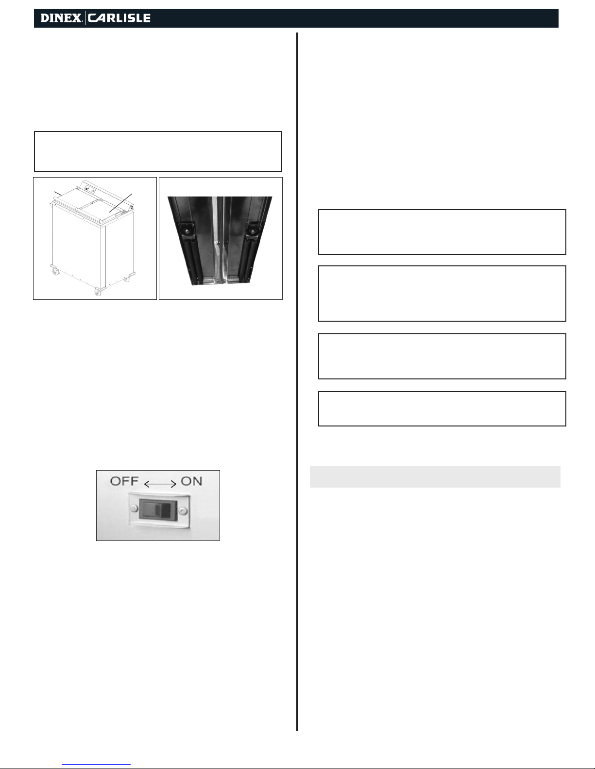
1. Turn the unit off, disconnect the plug from the outlet, and
allow the cabinet to cool. Remove plug by pulling it straight
out. Never pull on cord.
2. Pull the elevator mechanisms up and out, place them on a
work surface. You can wipe down the mechanisms with a
damp cloth to clean them.
3. Place the elevator mechanisms back inside the cabinet and
clean the outside of the cabinet with a mild, non-abrasive
soap or detergent in a warm water solution. A commercial
stainless steel cleaner can also be used for this procedure.
!NOTE: Do not use abrasives, harsh chemicals, or cholorine
products for cleaning.
!WARNING: Do not steam or pressure clean or hose down the
cabinet. This could damage the equipment and possibly cause an
electrical shock to the operator.
MAINTENANCE
ALARMS
Cabinet does not roll easily. 1. Debris on wheel or axle.
2. No lubrication.
1. Clean out debris.
2. Lubricate axles with load
bear
ing grease. Lubricate
swivel bearings with
30-weight oil.
Dispenser binds. 1. Improper springs
2. Debris on guide rods.
1. Depending on contents, use
correct number of springs,
make sure identical number
& size of springs are on each
dispenser.
2. Clean off debris.
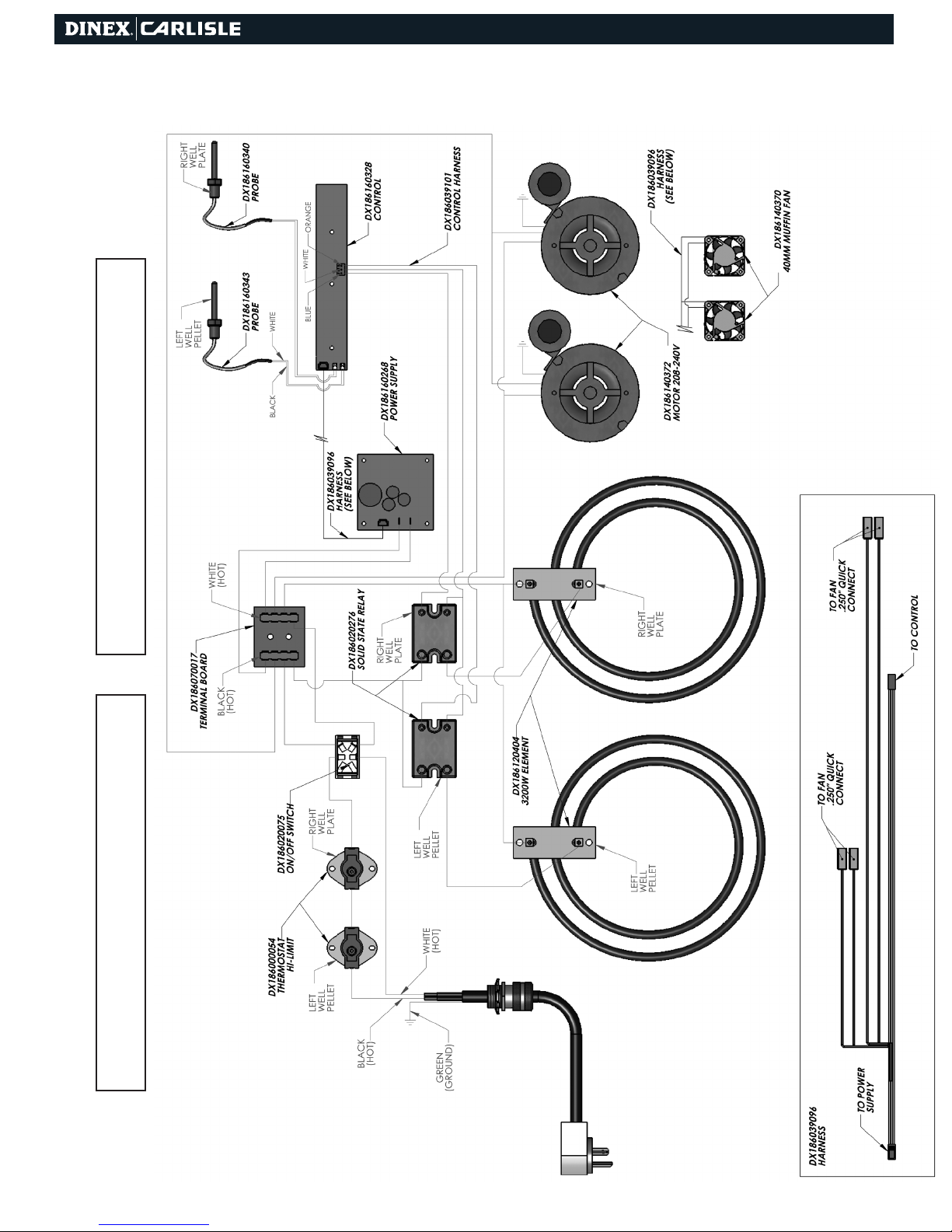
Unit heats, but fan does not
blow.
1. Defective motor.
2. Jammed or loose fan blade
3. Loose wiring.
1. Replace motor.
2. Replace or tighten blade.
3. Determine fault & correct.
Unit does not operate and
power indicator light does not
come on.
1. No power.
2. Open Hi Limit.
3. Defective power switch
4. Loose wiring
1. Make sure plug is connected
& switch is ON.
2. Check for power to receptacle.
3. Replace power switch.
4. Check and secure wiring.
Base/plate temperature is too
low, but fan is operating.
1. Thermostat set too low.
2. Fan blade is jammed or loose
3. Cover is open.
1. Readjust thermostat on
plate side. Replace
Thermostat on base side.
2. Replace or tighten blade.
3. Close cover.
Unit does not operate & light
does not come on.
1. No power.
2. Bad power switch.
3. Loose wiring.
1. Make sure plug is connected
& switch is ON. Check for
power to receptacle.
2. Replace power switch.
3. Check and secure wiring.
PROBLEM REMEDYPOSSIBLE
Base/ plate temperature is
too high, and fan is operating.
1. Thermostat is set too high.
2. Closed control.
3. Closed high limit switch.
1. Readjust thermostat on
china plate side. Replace
Thermostat on base side.
2. Replace control.
3. Replace high limit switch.
Casters
1. Check casters for freedom of movement and proper brake
operation.
2. Maintain casters free of debris. (mop strings, paper, plastic,
hair nets, etc.)
3. Clean or replace as required.
Cord and Plug
1. Inspect plug blades for distortion and replace if any blades
are missing, bent or broken.
2. Inspect cord wiring for integrity at termination points by
having qualified service person remove the back panel from
the cabinet. Make sure the cord sheathing extends into the
cabinet interior. If wires are showing on the outside of the
cabinet, remove the unit from use and have repairs made
before turning on power to the unit.
Dispensing Mechanism
Periodically check springs for proper dispensing by filling each
cavity with bases
/plates
and checking to see that it indexes as they
are removed. If bases
/plates
do not index properly, and unit is not
overloaded, adjust or replace springs.
Unit does not heat, but fan is
operating.
1. Loose wiring
2. Defective heating element.
1. Check & secure wiring.
2. Replace heating element.
TROUBLESHOOTING
!CAUTION: Thermostat adjustment should only be made by qualied
personnel. Thermostat adjustment not covered under warranty.
Lower Heater Base Cavity: 330°F
Upper Heater Base Cavity: 330°F
Lower Heater Plate Cavity: 210°F
Upper Heater Plate Cavity: 180°F
Default Temperature Setpoints:

Convection Heated Plate and Base Dispenser | 6
IDPWB2/0900
1 DX160953111 LID HINGE ASSY LEFT SIDE 1
2 DX160953112 LID HINGE ASSY RIGHT SIDE 1
3 DX160953113 LID HINGE ASSY MIDDLE 1
4 DX160902322 CORD SET 6-20P ANGLED 1
5 DX160953013 PUSH HANDLE ASSY 1
6 DX160953120 BASE DISPENSER ASSEMBLY 1
7 DX160953128 PLATE DISPENSER ASSEMBLY 1
8 DX183015267 3.5IN CASTER W/BRAKE 2
9 DX183015266 3.5IN CASTER 2
10 DX183050011 CORNER BUMPER BLACK 4
11 DX186000054 MANUAL RESET (HI LIMIT) 1
12 DX186020185 ON-OFF SWITCH 26A 1
13 DX186120404 1600W ELEMENT 2
14 DX186140345 FAN WHEEL 2
Description
Part Number Quantity
15 DX186140372 208/240V MOTOR 2
16 DX186160241 POWER SUPPLY BOARD 1
17 DX186160332
DX186160330
DX186160328
CONTROL - PLATE HEATER
CONTROL - BASE HEATER
CONTROL - COMBO
1
18 DX186070017 TERMINAL BLOCK 1
19 DX186160340 PROBE W/ CONECTOR 1
20 DX186160343 PROBE W/ CONECTOR 1
(Model DXIDPWB20900 Only)
21 DX186020276 SOLID STATE RELAY 1
22 DX160953016 LID ASSEMBLY 2
23 DX183120431
DX183120424
BASE/PLATE HEATER OVERLAY
COMBO UNIT OVERLAY
1
Description
Part Number Quantity
REPLACEMENT PARTS

Convection Heated Plate and Base Dispenser | 7
Base Dispenser Assembly
1 DX186170087 DISPENSER BUSHING 4
2 DX186170489 DISPENSER PULLEY 8
3 DX184002015 DISPENSER SPRING 9
Description
Part Number Quantity
6 DX160953128 BASE DISPENSER ASSEMBLY 1
Description
Part Number Quantity
Pulley bracket - DX165052092

Convection Heated Plate and Base Dispenser | 8
Plate Dispenser Assembly
1 DX186170087 DISPENSER BUSHING 4
2 DX186170489 DISPENSER PULLEY 8
3 DX184002015 DISPENSER SPRING 6
Description
Part Number Quantity
7 DX160953120 PLATE DISPENSER ASSEMBLY 1
Description
Parts Number Quantity

Convection Heated Plate and Base Dispenser | 9
Wiring Diagram (Model DXIDPWB20900)
!CAUTION: Disconnect power before servicing or resetting high-limit
thermostats. !
NOTE: All wires to be 10 Awg high temperature silicone insulated
unless otherwise specied.

Convection Heated Plate and Base Dispenser | 10
Wiring Diagram (Models DXIDPC20120 & DXIDWB20900)
!CAUTION: Disconnect power before servicing or resetting high-limit
thermostats. !
NOTE: All wires to be 10 Awg high temperature silicone insulated
unless otherwise specied.

Convection Heated Plate and Base Dispenser | 11
Wiring Diagram (Models DXIDPC30180 & DXIDWB30900)
!CAUTION: Disconnect power before servicing or resetting high-limit
thermostats. !
NOTE: All wires to be 10 Awg high temperature silicone insulated
unless otherwise specied.

Convection Heated Plate and Base Dispenser | 12
DINEX WARRANTY
These Warranties cover the following Dinex | Carlisle (“Dinex”)
equipment products (the “Warranted Products”):
• Rethermalization Equipment Products
• Induction Heating System Products (excluding Induction Bases
covered under separate warranty)*
• Milk Cooler Products
• Ice Cream Freezer Products
• Air Curtain Refrigerator Products
• Blast Chiller Products
• Hot/Cold Food Counter Products
• Plate, Rack and Tray Dispenser Products
• Plate Heater Products
• Base Heater Products
• Drying and Storage Rack Products
• Starter Station Products
• Conveyer Products
• Tray and Other Cart Products
Warranted Products also includes any other Equipment System
Products identied on Dinex’s website (www.dinex.com) from time to
time.
Standard Warranty. Except as indicated otherwise below, Dinex
warrants that the Warranted Products will be free from defects in
title, material and workmanship under normal use and service and
will perform substantially in accordance with Dinex’s written technical
specications for the Warranted Products (as such specications
exist on the date the Warranted Products are shipped) (the “Product
Specications” ) . This warranty covers both parts and labor and
is available only to end-users (the “Customers”) that purchase the
Warranted Products from Dinex or its authorized distributors. For the
purpose of these warranties, a defect is determined by Dinex after its
good faith investigation.
Dinex Software. In addition to the other warranties set forth herein, with
respect to Dinex’s licensed software, Dinex warrants that it has the right
to license or sublicense the software to Customer for the purposes and
subject to the terms and conditions set forth in Dinex’s standard terms
and conditions.
Supplies and Accessories. Dinex’s warranty for its supplies and
accessories that are shipped with Warranted Products is covered by a
separate warranty statement, which is available at www.dinex.com.
Services. Dinex warrants that any service it provides to Customer will
be performed by trained individuals in a workmanlike manner.
DURATION
Dinex provides a one year warranty for the Warranted Products*. The
warranty period begins on the date the Warranted Products are shipped
to Customer. The warranty period for any Warranted Product or part
furnished to correct a warranty failure will be the unexpired term of the
warranty applicable to the repaired or replaced Warranted Product.
*Turbo•Temp and Smart•Therm Induction Chargers are Warranted for
two years.
REMEDIES
If Customer promptly noties Dinex of Customer’s warranty claim and
makes the Warranted Product available for service, Dinex will, at its
option, either repair or replace (with new or exchange replacement
parts) the non-conforming Warranted Product or parts of the Warranted
Product. With respect to Dinex’s licensed software, Dinex will, at its
option, either correct the non-conformity or replace the applicable
licensed software. Warranty service will be performed without charge
from 8:00 a.m. to 5:00 p.m. CST, Monday - Friday, excluding Dinex
holidays, and outside those hours at Dinex’s then prevailing service
rates and subject to the availability of personnel. With respect to Dinex’s
warranty for the services it provides to Customer, Customer’s exclusive
remedy shall be the re-performance of the services by Dinex. The
foregoing remedies are Customer’s exclusive remedies and Dinex’s
sole liability for warranty claims under this warranty statement. This
exclusive remedy shall not have failed of its essential purpose (as
that term is used in the Uniform Commercial Code) as long as Dinex
remains willing to repair or replace defective Warranted Products within
a commercially reasonable time after being notied of Customer’s
warranty claim.
LIMITATIONS
THESE WARRANTIES ARE EXCLUSIVE AND IN LIEU OF ALL
OTHER WARRANTIES, WHETHER WRITTEN, ORAL, EXPRESSED,
IMPLIED OR STATUTORY. EXCEPT AS PROVIDED HEREIN, NO
EXPRESS OR IMPLIED WARRANTIES, INCLUDING BUT NOT
LIMITED TO IMPLIED WARRANTIES OF MERCHANTABILITY,
FITNESS FOR A PARTICULAR PURPOSE, QUIET ENJOYMENT,
SYSTEM INTEGRATION AND DATA ACCURACY, WILL APPLY.
THERE ARE NO WARRANTIES THAT EXTEND BEYOND THOSE
DESCRIBED IN THIS DOCUMENT AND NO PRIOR STATEMENTS BY
ANY OF DINEX’S REPRESENTATIVES SHALL MODIFY OR EXPAND
THESE WARRANTIES. DINEX AND DINEX’S AFFILIATES AND
REPRESENTATIVES SHALL HAVE NO LIABILITY TO CUSTOMER
FOR (1) ANY SPECIAL, PUNITIV E, INCIDENTAL, INDIRECT
OR CONSEQUENTIAL DAMAGES ARISING OUT OF OR IN
CONNECTION WITH THE WARRANTED PRODUCTS, REGARDLESS
OF WHETHER SUCH LIABILITY SHALL BE CLAIMED IN CONTRACT,
TORT, EQUITY OR OTHERWISE, (2) ANY ASSISTANCE NOT
REQUIRED UNDER DINEX’S QUOTATION OR (3) ANYTHING
OCCURRING AFTER THE WARRANTY PERIOD ENDS.
DINEX’S STANDARD WARRANTIES ONLY APPLY TO END-USER-
PURCHASERS LOCATED IN THE UNITED STATES AND CANADA.
ANY SALE TO END-USER-PURCHASERS OUTSIDE THE UNITED
STATES AND CANADA WILL BE SUBJECT TO COMMERCIAL
TERMS SPECIFICALLY AGREED BY DINEX AND THE END-USER
PURCHASER. DINEX MAKES NO WARRANTY, EXPRESS OR
IMPLIED, TO END-USER-PURCHASERS OUTSIDE THE UNITED
STATES OR CANADA UNLESS OTHERWISE EXPRESSLY AGREED
IN WRITING.
These warranties do not apply to, and Dinex shall not have any
obligation to Customer hereunder with respect to, any warranty claim
resulting from or arising out of: (i) normal wear and tear; (ii) damage
caused by shipping or accident; (iii) damage caused by improper
installation, repair or alteration not performed by Dinex; (iv) the use
of the Warranted Product in combination with any software, tools,
hardware, equipment, supplies, accessories or any other materials or
services, not furnished by Dinex or recommended in writing by Dinex;
(v) the use of the Warranted Product in a manner or environment,
or for any purpose, for which Dinex did not design or license it, or
inconsistent with Dinex’s recommendations or instructions on use
including, but not limited to, power supply requirements identied in
Product Specications; (vi) any alteration, modication or enhancement
of the Warranted Product by Customer or any third party not authorized
or approved in writing by Dinex; (vii) Warranted Product manufactured
to meet customer specications or designs; or (viii) any accessories or
supplies or other equipment or products that may be delivered with the
Warranted Product .
In addition, these warranties do not cover: (i) Any defect or deciency
(including failure to conform to Product Specications) that results,
in whole or in part, from any improper storage or handling, failure
to maintain the Warranted Products in the manner described in any
applicable instructions or specications, inadequate backup or virus
protection or any cause external to the Warranted Products or beyond
Dinex’s reasonable control, including, but not limited to, power failure
and failure to keep Customer’s site clean and free of dust, sand and
other particles or debris; (ii) the payment or reimbursement of any
facility costs arising from repair or replacement of the Warranted
Products; (iii) any adjustment, such as alignment, calibration, or other
normal preventative maintenance required of Customer; and (iv)
expendable supply items.

NOTES:
Convection Heated Plate and Base Dispenser | 13

© 2011 DINEX | CARLISLE • 4711 EAST HEFNER ROAD, OKLAHOMA CITY, OK 73131 • WWW.DINEX.COM
Manual No. Plate_Base_Heater_0411
This manual suits for next models
4
Table of contents
Popular Commercial Food Equipment manuals by other brands

Diamond
Diamond G9/PLCA4 operating instructions

KBS
KBS Tecfrigo FISHING 4 Installation and use manual

Maxima
Maxima 09374060 user manual

etol
etol blu'box 26 SMART eco Original user manual

Federal
Federal VRSS Series Installation & operation instructions

Henny Penny
Henny Penny Evolution Elite 14X quick reference