DINSE DIX GO 1156.M Puls User manual

DIX PI GO 1156.M
BA-0124
Welding Power Source
SCHWEISSEN WELDING WELDINGSCHWEISSEN SCHWEISSEN
Keepinsecureareaforfuturereference!
Operations manual

2
Introduction 2
Description 2
Technical data 3
Usage limits (IEC 60974-1) 3
How to lift up the welding power source 4
Open the packaging 4
Installation and connections 4
Connecting the welding welding power source to
the utility line 4
Command and control units (Fig.A) 4
Loading wire 5
Assembly of drive roller 5
MIG-MAG welding with GAS 6
MIG-MAG welding without GAS 7
Spot welding 7
Interval welding (Stitch) 8
Aluminium welding 8
TIG welding with “Lift” 8
Electrode welding (MMA) 9
Maintenance 9
The pointing out of any difficulties and their
elimination 10
Replacing the digital interface PCB 10
Troubleshooting table 11
Electro topographical diagram 12
Electro topographical diagram key 13
Meaning of graphic symbols on welding power
source 13
Colour key 13
Description
MULTI-FUNCTION INVERTER WELDING POWER SOURCE
SUITABLE FOR SINGLE-PHASE POWER SUPPLIES FOR
MIG-MAG, MMA, and TIG WELDING (with “Lift” type igni-
tion)
Multifunction synergic welding power source, based on the
leading-edge IGBT inverter technology and fully digitally con-
trolled, offer premium welding quality MIG/MAG on all materi-
als, especially stainless steel, aluminium and galvanized steel;
the spatter-free welding feature minimises reprocessing work.
It also ensures excellent performance in TIG and MMA weld-
ing prcesses.
Innovative, versatile, light-weight, easily portable, simple to use,
DIX PI GO 1156.M is a very high level product that is abso-
lutely irreplaceable technologically for all internal and external
maintenance works, vehicle bodyworks, agricultural and small
light metalwork jobs.
The principal characteristics of welding units are:
•
Multifunction power source with premium welding quality in
MIG/MAG, MMAand TIG with “Lift” type ignition welding pro-
cesses.
•
Standard polarity inversion for welding with the most com-
mon core wires and without gas.
• Central Euro connection on torch.
• Innovative practical design.
•
Supporting structure in metal with front panel in special
shockproof material.
• Protective visor on the control panel.
• Robust handle integrated into the chassis.
•
Professional 2-roller wire feeder that guarantees precise
feeding of the wire.
•
The double slot rollers can be replaced without using any
tools.
•
Agraduated knob for precise adjustment of the wire pressure
that stays unvaried when the arms open and close.
• Housing for coils of wire with max Ø 200 mm – 5 kg.
• Synergic digital control of all welding parameters, shown on
the display, also featuring the following functions:
-
Allows less expert operators to regulate all welding param-
eters, choosing the type of program on the basis of the ma-
terial, wire diameter, and gas used.
-
Innovative software “DIX ARC” for controlling all welding
parameters.
-
Digital Voltmeter /Ammeter with HOLD function (saving of
latest data on both displays).
-
“Energy Saving” function to operate the power source cool-
ing fan only when necessary.
- Auto-diagnostic feature for trouble shooting.
- Ability to store personalized welding programmes (JOB).
- MIG-MAG welding:
- BURN BACK control. At the end of each weld, in any
condition and with any material, the digital control en-
sures a perfect wire cut, prevents the typical “wire glob-
ule” from forming and ensures correct arc restriking.
-
WSC Wire start control. This arc striking control device
prevents wire from sticking to the workpiece or torch
nozzle and ensures precise and smooth arc striking,
particularly when welding aluminium.
-
Welding parameters that are controlled digitally by a
microprocessor, are monitored and modified in just a
few seconds, maintaining a consistently precise and
stable arc as the welding conditions continue to vary
due to the movement of the torch and the irregularities
of the parts to be welded.
Introduction
Thank you for buying our product.
In order to get the best performance out of the equipment and
ensure the maximum lifespan of its parts, the use and mainte-
nance instructions contained in this manual must be read and
strictly complied with, as well as the safety instructions con-
tained in the relevant folder. If repairs to the equipment are
required, we recommend that our clients contact our service
centre workshops, as they have the necessary equipment and
personnel that are specifically trained and constantly updated.
All our welding power sources and equipment are constantly
developed and so changes may be made in terms of their con-
struction and features.
DINSE G.m.b.H.
Tarpen 36 • D-22419 Hamburg
Tel. +49 (0)40 658 75-0
Fax +49 (0)40 658 75-200
Copyright © 2018 DINSE G.m.b.H., Hamburg.
Theseinstructionsorexcerptsthereofshallnotbeduplicated,translatedorreprodu-
ced, nor shall they be stored, processed, transmitted or distributed by any electronic
means without the prior written permission of DINSE G.m.b.H.
3
- MMAwelding:
-
“Arc Force” adjustable to select the best dynamic char-
acteristics for the welding arc.
- “Hot Start” adjustable to improve ignition with particu-
larly difficult electrodes.
- Anti-sticking function to avoid the electrodes sticking.
-
Vrd (Voltage Reduction Device), which makes it pos-
sible to use the welding power source in environments
where the risk of electric shock or electrocution caused
by arc welding is enormously increased by the pres-
ence of water, humidity, or heat, and particularly where
the ambient temperature exceeds 32°C.
- TIG welding:
-
“Lift” type ignition, with TCS “Thermal Control Start” de-
vice to further reduce tungsten inclusions.
-
Exclusive SWS “Smart Welding Stop” system at the
end of TIG welding. Lifting up the torch without switch-
ing off the arc will introduce a SLOPE DOWN and it will
switch off automatically.
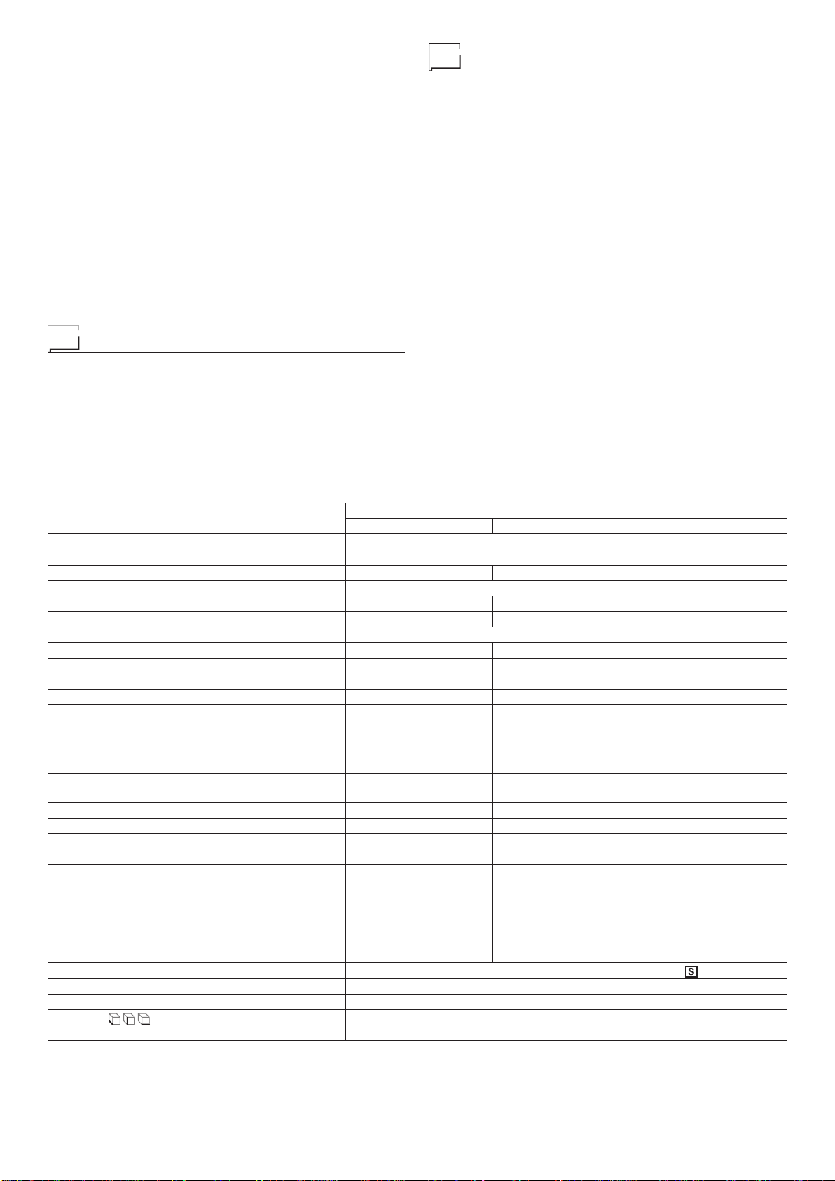
Technical data
The general technical data of the system are summarized in
table 1.
Usage limits (IEC 60974-1)
The use of a welder is typically discontinuous, in that it is made
up of effective work periods (welding) and rest periods (for the
positioning of parts, the replacement of wire and underflushing
operations etc. This welder is dimensioned to supply a I2max
nominal current in complete safety for a period of work of X%
of the total usage time. The regulations in force establish the
total usage time to be 10 minutes. The work cycle is considered
to be X% of this period of time. When the work cycle permit-
ted is exceeded a trip switch trips, which protects the welding
power source’s internal components against dangerous over-
heating and prevents incorrect functioning of the welding power
source.After several minutes the overheat cut-off rearms auto-
matically and the welder is ready for use again (Automatic re-
set error). This equipment is built to have a protection level of
IP 23 S, which means:
•
That it is protected against the penetration of solid foreign
bodies with diameters in excess of Ø 12 mm.
•
That it is protected against water spray hitting the surface
with an angle of incidence up to 60°.
• That the equipment has been tested for withstanding harm-
ful effects due to water getting in when the moving parts on
the equipment are moving.
Table 1
Model DIX PI GO 1156.M
MIG-MAG TIG MMA
Single-phase input 50/60 Hz V230 ± 15%
Mains supply: Zmax (*) Ω0,21
Power input (I2Max) kVA 8,1 6,4 7,8
Delayed fuse (Ieff) A16
Power factor / cosφ 0,63 / 0,99 0,63 / 0,99 0,63 / 0,99
Efficiency degree η0,83 0,8 0,83
Voltage without load V60
Current range A10 ÷ 175 5 ÷ 175 10 ÷ 150
Duty cycle @ 100% (40°C) A100 100 90
Duty cycle @ 60% (40°C) A115 115 110
Duty cycle @ X% (40°C) A175 (20%) 175 (20%) 150 (25%)
Wires diameter mm
•0,6/0,8/1,0 - Fe
•1,0 / 1,2 - Al
•0,8 / 1,0 - CrNi
•0,8 / 1,0 - Cu Si 3
•0,9 - Flux Cored
- -
Spool
Diameter / Weight mm / kg 200 / 5 - -
N° rollers 2 - -
Power output of feeder motor W40 - -
Rated wire feeding speed m/min 1 - 20 - -
MMAelectrodes mm - - 1,6 - 3,2
TIG electrodes mm -1,0 - 3,2 -
Protection gas
•Carbon dioxide
•Pure Argon
•Argon - Carbon dioxide
- Oxygen
•Argon and Carbon
dioxide blends
- -
Standards IEC 60974-1 - IEC 60974-5 - IEC 60974-10 -
Protection class IP 23 S
Insulation class H
Dimensions mm 500 - 425 - 220
Weight kg 16
(*) Mains supply Zmax: maximum impedance value allowed for the grid according to the EN/IEC 61000-3-11 standard.
WARNING: This equipment does not comply with EN/IEC 61000-3-12. If it is connected to a public low voltage system, it is the responsibility
of the installer or user of the equipment to ensure, by consultation with the distribution network operator if necessary, that the equipment may
be connected.

4
How to lift up the welding power source
The welding power source has a strong handle all in one with
the frame, used for transporting the welding power source man-
ually only.
NOTE: These hoisting and transportation devices conform to
European standards. Do not use other hoisting and transpor-
tation systems.
Open the packaging
Upon receiving the system:
•
Remove the welding power source and all relevant accesso-
ries-components from their packaging.
• Check that the welding power source is in good condition, if
not report any problems immediately to the seller-distributor.
• Make sure all ventilation grilles are open and that no foreign
bodies are blocking the air circulation.
Installation and connections
The installation site for the system must be carefully chosen
in order to ensure its satisfactory and safe use. The user is re-
sponsible for the installation and use of the system in accord-
ance with the producer’s instructions contained in this manual.
Before installing the system the user must take into consider-
ation the potential electromagnetic problems in the work area.
In particular, we suggest that you should avoid installing the
system close to:
• Signalling, control and telephone cables.
• Radio and television transmitters and receivers.
• Computers and control and measurement instruments.
• Security and protection instruments.
Persons fitted with pace-makers, hearing aids and similar
equipment must consult their doctor before going near a weld-
ing power source in operation. The equipment’s installation
environment must comply to the protection level of the frame
i.e. IP 23 S (IEC 60529 publication). The system is capable of
working in environments where working conditions are partic-
ularly hard.
This system is cooled by means of the forced circulation of air,
and must therefore be placed in such a way that the air may
be easily sucked in and expelled through the apertures made
in the frame.
The equipment must be assembled as follows:
• Mount on the trolley (optional extra).
• Fix the welding unit to the trolley.
• Connect the welding welding power source to the utility line.
• Connect up the welding cables.
Connecting the welding welding
power source to the utility line
Connection of the welding power source to the user line
(electrical current) must be performed by qualified per-
sonnel.
Before connecting the welding welding power source to
the mains power supply, make sure that rated voltage and
frequency correspond to those provided by the mains pow-
er supply and that the welding welding power source’s
power switch is turned to “O”.
Connection to the power supply must be carried out using the
tripolar cable supplied with the system, of which:
•
2 conducting wires are needed for connecting the welding
power source to the supply.
•
The third, which is YELLOW GREEN in colour is used for
making the “GROUND” connection.
Connect a suitable load of normalised plug (2p + e) to the
power cable and provide for an electrical socket complete
with fuses or an automatic switch. The ground terminal
must be connected to the ground conducting wire (YEL-
LOW-GREEN) of the supply.
Table 2 shows the capacity values that are recommended for
fuses in the line with delays.
NOTE: Any extensions to the power cable must be of a suita-
ble diameter, and absolutely not of a smaller diameter than the
special cable supplied with the welding power source.
Command and control units (Fig. A)
Pos. 1 control panel.
Pos. 2 Fast coupling straight polarity.
Pos. 3 Fast coupling reverse polarity.
Pos. 4 Centralised MIG-MAG torch connection.
Pos. 5 Power supply switch. In the “O” position the welder
is off.
Pos. 6 Mains cable.
Pos. 7 Weld gas inlet coupling.
Pos. 8 Cable clamp for the welding cable to pass (with the
“Retrofit kit adaptor” fitted).
Loading wire
• Open the side panel on the left using the relevant Allen key
and insert the coil (use coils with a MAX diameter of 200 mm
and MAX weight of 5 kg) that suits the material to be welded
on the relevant support so that the wire unwinds anticlock-
wise and aligning the protruding marker on the support with
the relevant hole in the coil.
Table 2
Model DIX PI GO 1156.M
MIG-MAG TIG MMA
Power input (I2Max) kVA 8,1 6,4 7,8
Delayed fuse (Ieff) A16
Duty cycle @ X% (40°C) A175 (20%) 175 (20%) 150 (25%)
Mains cable
Length
Section m
mm23
2,5
Ground cable
Length
Section m
mm23
16

5
FIG. A
12
3
4
5
6
7
FIG. B
• Thread the end of the wire into the back guide (Pos. 7, Fig.
B) on the drawing mechanism.
• Lift up the idle roller Ø 26 mm (Pos. 1, Fig. B) releasing the
roller pressure mechanism (Pos. 6, Fig. B). Check that the
drive roller (Pos. 4, Fig. B) has the diameter corresponding
to the wire being used printed on the outer side.
• Thread the wire into the central wire guide and into the wire
guide of the centralized attachment (Pos. 3, Fig. B) for a few
centimetres. Lower the idle roll-holder arm making sure the
wire goes into the slot of the drive roll. If necessary, adjust the
pressure between the rollers with the screw provided (Pos.
5, Fig. B). The correct pressure is the minimum that does not
allow the rollers to skid on the wire. Excessive pressure will
case deformation of the wire and tangling on the entrance of
the sheath; insufficient pressure can cause irregular welding.
Assembly of drive roller
Follow instructions given below for mounting the drawing roll-
er onto the mechanism:
• Unscrew the screw (Pos. 5, Fig. B).
• Lift up the idle roll-holder arm Ø 26 mm (Pos. 2, Fig. B).
•
Each roller shows the type of wire and diameter on the two
external sides.
•
Mount the appropriate roller (Pos. 4, Fig. B) making sure the
groove is in the right position for the diameter of the wire be-
ing used.
• Screw the screw (Pos. 5, Fig. B).
MIG-MAG welding with GAS
To begin MIG-MAG welding, carry out the following tasks (with
the welding power source switched off):
1 - Connecting the cables (Fig. C1-C2)
1) Connect the gas hose to the pressure reducer fitted on
the cylinder beforehand. Gas cylinders are supplied with
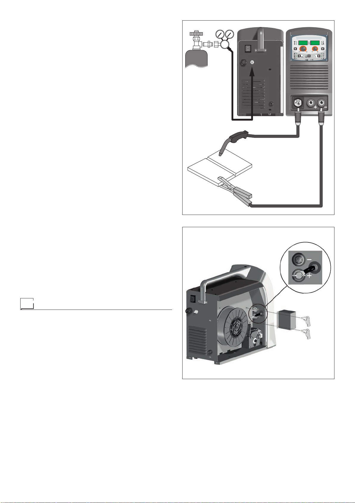
6
a pressure reducer to adjust pressure of the gas used for
welding.
2) Screw the torch to the centralised connection on the front
panel of the welding welding power source (Pos. 4, Fig.A).
3) Connect up the earthing system cable to the rapid cou-
pling marked by a - (negative) symbol and then the rel-
evant ground clamps to the piece being welded or to its
support in an area free from rust, paint and grease. Using
particularly long earthing cables reduces the voltage and
causes some problems from increased resistance and in-
ductance of the cables that could cause faulty welding. Fol-
low instructions to avoid these problems:
•
Use earthing and extension cables with appropriate sec-
tion.
• Lay out the cables as a flat as possible to prevent them
from coiling up.
4) Open the moving cover, remove the protection box for
changing polarity (see Fig. C2) and make sure that the
change polarity cable is connected to the positive pole (+).
2 - Welding
1) Open the moving cover and fit the coil of wire.
2) Load the wire (see the “Loading the wire” paragraph).
3) Switch the welding welding power source on by moving the
power supply switch to I(Pos. 5, Fig. A).
4) Carry out the following operations on the MIG-MAG torch:
•
Remove the gas-guide and wire-guide nozzles, allowing
the wire to flow freely during loading. Remember that the
contact tip must correspond to the wire diameter.
•
Push the torch push button or the motor check push but-
ton until the wire end comes out from the torch.
• Tighten the contact tip on the torch.
• Attach the correct gas-guide nozzle.
• Protect the gas-guide nozzle and the wire-guide nozzle
of the torch from sprays of solder.
5) Make the adjustments and select the parameters on the
control panel.
6) Open the tap on the cylinder slowly and adjust the reduc-
er knob to obtain a pressure of about 1,0 to 1,5 bar, and
regulate the flow to about 15 lit/min (to suit the current to
used for welding).
7) The welding welding power source is ready for welding. To
begin welding, approach the point to be welded and press
the button on the torch.
8) When you have finished welding, remove the waste, turn
off the welding power source and close the gas cylinder.
MIG-MAG welding without GAS
To begin MIG-MAG welding without gas, carry out the following
tasks (with the welding power source switched off):
1 - Connecting the cables (Fig. D1-D2)
1) Screw the torch to the centralised connection on the front
panel of the welding welding power source (Pos. 4, Fig.A).
2) Connect up the earthing system cable to the rapid cou-
pling marked by a + (positive) symbol and then the relevant
ground clamps to the piece being welded or to its support in
FIG. C2
FIG. C1
2000HB98

7
an area free from rust, paint and grease. Using particularly
long earthing cables reduces the voltage and causes some
problems from increased resistance and inductance of the
cables that could cause faulty welding. Follow instructions
to avoid these problems:
•
Use earthing and extension cables with appropriate sec-
tion.
• Lay out the cables as a flat as possible to prevent them
from coiling up.
3) Open the moving cover, remove the protection box for
changing polarity (see Fig. D2) and move the change po-
larity cable, connecting it to the negative pole (-).
2 - Welding
1) Open the moving cover and fit a coil of wire with a core for
welding without using gas.
2) Load the wire (see the “Loading the wire” paragraph).
3) Switch the welding welding power source on by moving the
power supply switch to I(Pos. 5, Fig. A).
4) Carry out the following operations on the MIG-MAG torch:
•
Remove the gas-guide and wire-guide nozzles, allowing
the wire to flow freely during loading. Remember that the
contact tip must correspond to the wire diameter.
•
Push the torch push button or the motor check push but-
ton until the wire end comes out from the torch.
• Tighten the contact tip on the torch.
• Attach the correct gas-guide nozzle.
• Protect the gas-guide nozzle and the wire-guide nozzle
of the torch from sprays of solder.
5) Make the adjustments and select the parameters on the
control panel. Make sure that you have selected a program
that is suitable for wire with a core.
6) The welding welding power source is ready for welding. To
begin welding, approach the point to be welded and press
the button on the torch.
7) Once welding has been completed remove the slag and
switch off the welding power source.
Spot welding
FIG. E
Welding can be done with or without gas. The substantial dif-
ference with MIG-MAG welding is essentially related to the
torch and the adjustments that must be made on the TS con-
trol panel.
• Depending on the torch chosen and the work to be done, a
gas guide nozzle can be fitted on the torch that is specifical-
ly for spot welding (see Fig. E).
• Use the control panel to select the spot-welding mode and,
if necessary, make the changes to the related “Special func-
tions - Fx”, which allows the welding power source to do this
specific type of welding.
To begin spot welding:
•
Place the gas guiding nozzle perpendicular on the workpiece
to be spot welded.
•
Press the torch button to start the welding current and wire
feed.
•
When the spot welding time expires (SPOT WELD TIME),
the wire feed stops automatically.
•
When the torch button is pushed again a new welding cy-
cle starts.
• Release the torch button.
FIG. D1
FIG. D2
2000HB99

8
FIG. F
Interval welding (Stitch)
The substantial differences with the spot welding mainly con-
cern the adjustments that must be carried on the welding weld-
ing power source.
Use the control panel to select the interval welding mode and
then make the changes to the related “Special functions - Fx”,
which allows the welding power source to do this specific type
of welding.
To begin interval welding:
•
Press the torch button to start the welding current and wire
feed.
•
At this point the welding welding power source automatically
carries out a succession of welded portions (STITCH WELD
TIME) followed by a pause (STITCH WELD PAUSE), ac-
cording to the times entered previously. This procedure stops
automatically only when the TORCH BUTTON is released.
•
When the torch button is pushed again the torch begins a
new interval welding cycle.
Aluminium welding
To weld with aluminum wire proceed as follows:
•
Replace the drive roller with the appropriate for aluminum
wire.
•
We recommend to use a torch set with maximum lenght of
3 m and a capillary liner, e.g. DIX DSK 2-xx.
•
Set the pressure between the drive rollers at the minimum,
by turning the screw provided.
• Use argon gas at a pressure of 1,3 - 1,7 bar.
TIG welding with “Lift”
In the TIG process welding is achieved by melting the two metal
pieces to be joined, with the possible addition of material from
the outside, using an arc ignited by a tungsten electrode. The
“Lift” (TCS) type ignition used in the equipment makes it pos-
sible to reduce tungsten inclusions on ignition to a minimum.
The molten bath and the electrode are protected by and inert
gas (for example,Argon). This type of welding is used to weld
thin sheet metal or when elevated quality is required.
1) Connecting the welding cables (Fig. F):
•
Connect one end of the gas hose to the gas connecter on
the TIG torch and the other end to the pressure reducer
on the inert gas cylinder (Argon or similar).
• With the welding power source switched off:
-
Connect the ground cable to the snap-on connector
marked + (positive).
-
Connect the relative ground clamp to the workpiece or
to the workpiece support in an area free of rust, paint,
grease, etc..
-
Connect the TIG torch power cable to the snap-on con-
nector marked - (negative).
2) Switch the welding welding power source on by moving the
power supply switch to I(Pos. 5, Fig. A).
3) Make the adjustments and do the parameter settings on
the control panel.
4) Open the gas cylinder and regulate the flow by adjusting
the valve on the TIG torch by hand.
5) Ignite the electric arc by contact, using a decisive, quick
movement without dragging the tungsten electrode on the
piece to be welded (“Lift” type ignition - Fig. G).
6) The welder has a SWS “Smart Welding Stop” system for
the end of TIG welding. Lifting up the torch without switch-
ing off the arc will introduce a slope down and it will switch
off automatically.
7) When you have finished welding remember to shut the
valve on the gas cylinder.
Table 3 shows the currents to use with the respective elec-
trodes for TIG DC welding. This input is not absolute but is for
your guidance only; read the electrode manufacturers’instruc-
tions for a specific choice. The diameter of the electrode to use
is directly proportional to the current being used for welding.
Table 3
Ø ELECTRODE
(mm)
ELECTRODE TYPE
Current adjustment field (A)
TIG DC
Tungsten
Ce 1%
Grey
Tungsten
Rare ground 2%
Turchoise
110-50 10-50
1,6 50-80 50-80
2,4 80-150 80-150
3,2 150-250 150-250
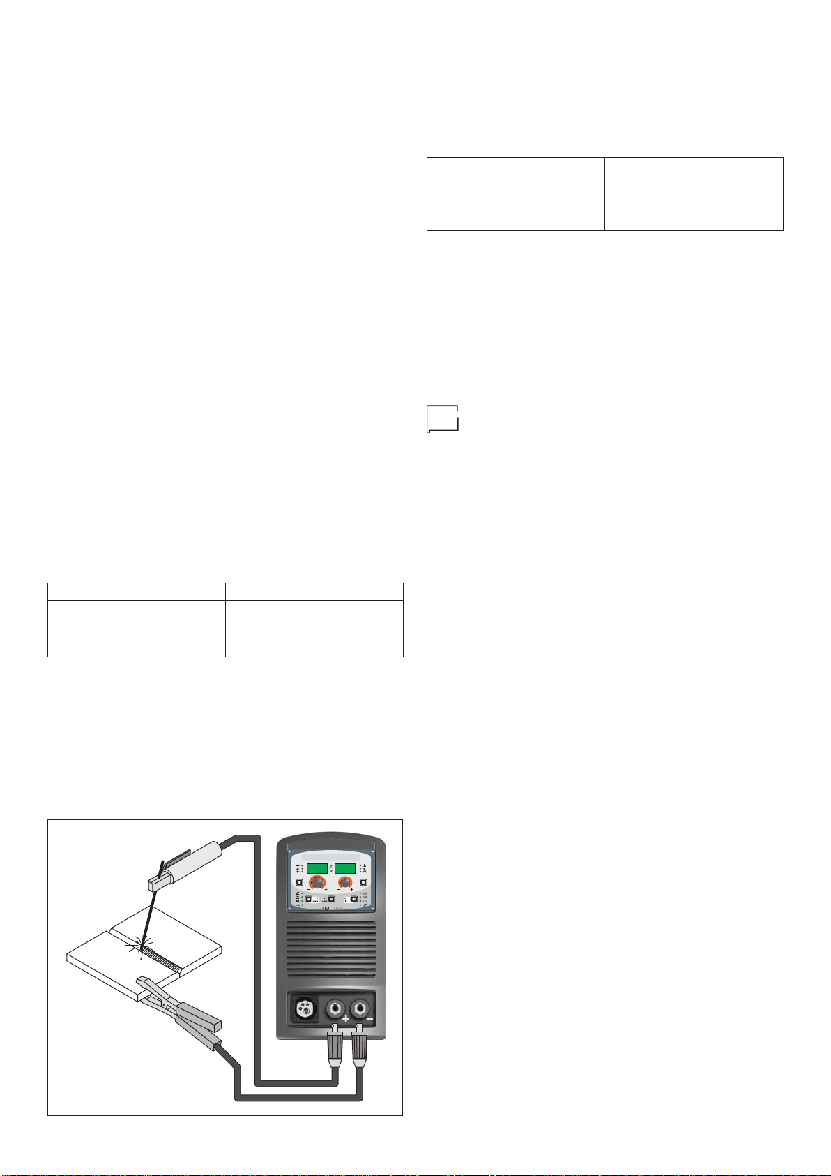
Electrode welding (MMA)
Electrode welding is used to weld most metals (different types
of steel, etc.) using coated rutilic and basic electrodes with di-
ameters ranging from Ø 1.6 mm to Ø 3,2 mm.
1) Connecting the welding cables (Fig. H):
Disconnect the welding power source from the mains pow-
er supply and connect the welding cables to the output
terminals (Positive and Negative) of the welding welding
power source, attaching them to the clamp and ground
with the polarity specified for the type of electrode being
FIG. G
2000HA86
9
used (Fig. H). Always follow the electrode manufacturer’s
instructions. The welding cables must be as short as pos-
sible, they must be near to one another, positioned at or
near floor level. Do not touch the electrode clamp and the
ground clamp simultaneously.
2) Switch the welding welding power source on by moving the
power supply switch to I(Pos. 5, Fig. A).
3) Make the adjustments and select the parameters on the
control panel.
4) Carry out welding by moving the torch to the workpiece.
Strike the arc (press the electrode quickly against the met-
al and then lift it) to melt the electrode, the coating of which
forms a protective residue. Then continue welding by mov-
ing the electrode from left to right, inclining it by about 60°
compared with the metal in relation to the direction of weld-
ing.
PART TO BE WELDED
The part to be welded must always be connected to ground
in order to reduce electromagnetic emission. Much attention
must be afforded so that the ground connection of the part to
be welded does not increase the risk of accident to the user or
the risk of damage to other electric equipment. When it is nec-
essary to connect the part to be welded to ground, you should
make a direct connection between the part and the ground
shaft. In those countries in which such a connection is not al-
lowed, connect the part to be welded to ground using suitable
capacitors, in compliance with the national regulations.
WELDING PARAMETERS
Table 4 shows some general indications for the choice of elec-
trode, based on the thickness of the parts to be welded. The
values of current to use are shown in the table with the respec-
tive electrodes for the welding of common steels and low-grade
alloys. These data have no absolute value and are indicative
data only. For a precise choice follow the instructions provided
by the electrode manufacturer.
Table 4
WELDING THICKNESS (mm) Ø ELECTRODE (mm)
1,2 ÷ 2
1,5 ÷ 3
3 ÷ 5
5 ÷ 12
1,6
2
2,5
3,2
The current to be used depends on the welding positions and
the type of joint, and it increases according to the thickness and
dimensions of the part.
The current intensity to be used for the different types of weld-
ing, within the field of regulation shown in table 5 is:
• High for plane, frontal plane and vertical upwards welding.
• Medium for overhead welding.
•
Low for vertical downwards welding and for joining small pre-
heated pieces.
Table 5
Ø ELECTRODE (mm) CURRENT (A)
1,6
2
2,5
3,2
30 ÷ 60
40 ÷ 75
60 ÷ 110
95 ÷ 140
Afairly approximate indication of the average current to use in
the welding of electrodes for ordinary steel is given by the fol-
lowing formula: I = 50 × (Øe - 1)
Where:
I = intensity of the welding current
Øe = electrode diameter
Example:
For electrode diameter 4 mm
I = 50 × (4 - 1) = 50 × 3 = 150A
Maintenance
ATTENTION: Cut off the power supply to the equipment be-
fore effecting any internal inspection.
DIX PI GO 1156.M
IMPORTANT: Since the welding welding power sources are ful-
ly electronic, removing the dust that is sucked into the welding
power source by the fans, is of utmost importance.
In order to achieve correct functioning of the welding power
source, proceed as described:
•
Periodic removal of accumulations of dirt and dust inside the
equipment using compressed air. Do not point the jet of air
directly at the electrical parts as this could damage them.
•
Periodical inspection for worn cables or loose connections
that could cause overheating.
•
Make sure the air circuit is completely free of any impuri-
ties and that the connections are tight and free of any leaks.
In this connection, inspect the solenoid valve very carefully.
•
Check the wire feeder rolls periodically and replace them
when wear impairs the regular flow of the wire (slipping etc).
TORCH
The torch is subjected to high temperatures and is also stressed
by traction and torsion. We recommend not to twistthe wire and
not to use the torch to pull the welder. As a result of the above
the torch will require frequent maintenance such as:
• Cleaning welding splashes from the gas diffuser so that the
gas flows freely.
• Substitution of the contact point when the hole is deformed.
•
Cleaning of the wire guide liner using trichloroethylene or
specific solvents.
• Check of the insulation and connections of the power cable;
the connections must be in good electrical and mechanical
condition.
SPARE PARTS
Original spares have been specifically designed for our equip-
ment. The use of spares that are not original may cause vari-
ations in the performance and reduce the safety level of the
equipment. We are not liable for damage due to use of spare
parts that are not original.
FIG. H

10
The pointing out of any difficulties
and their elimination
The supply line is attributed with the cause of the most com-
mon difficulties. In the case of breakdown, proceed as follows:
1) Check the value of the supply voltage.
2) Check that the power cable is perfectly connected to the
plug and the supply switch.
3) Check that the power fuses are not burned out or loose.
4) Check whether the following are defective:
• The switch that supplies the welding power source.
• The plug socket in the wall.
• The mains switch.
NOTE: Given the required technical skills necessary for the
repair of the welding power source, in case of breakdown we
advise you to contact skilled personnel or our technical ser-
vice department.
Replacing the digital interface PCB
Proceed as follows:
• Unscrew the 4 screws that fix the front rack panel.
• Remove both the adjustment knobs.
• Disconnect the electrical connectors for the board.
• Unscrew the support columns.
• Remove the electronic board by lifting it off its supports.
• To fit a new board, follow this procedure in reverse.

11
Troubleshooting table
WARNING: Any internal inspections or repairs are only to be done by qualified personnel!
IMPORTANT: Remember to disconnect the mains power supply and wait for the internal capacitors to discharge (about 2 min-
utes) before starting to check and repair the welding power source if necessary.
Defect Solution
The welding welding power
source does not switch on,
control panel switched off.
• Check that the welding welding power source is installed correctly and that the
mains supply has sufficient power to supply the welding welding power source.
• Check the switch, cable and plug on the power supply line and replace them if necessary.
• Check, and if necessary replace, the digital interface PCB or the control PCB.
Line fuses fused
“instantaneously”. • Check that the welding welding power source is installed correctly.
• Check and if necessary replace the motor, transformer, or rectifier.
Line fuses fused after
a work period. • Check that you have fitted line fuses of adequate absorption capacity.
Welding welding power
source on, control panel
on, fan stopped.
• Check the wiring that powers the fans.
• Check that there are no mechanical impediments blocking the fans.
• Check and if necessary replace the digital interface PCB.
Welding welding power
source on, display does
not show correct values.
• See the error codes and signals shown in this manual.
• Check the wiring that powers the various boards.
• Check, and if necessary replace, the digital interface PCB or the control PCB.
No gas coming out of the torch. • Check and if necessary replace the solenoid valve or gas hose.
• Check the wiring that powers the gas solenoid valve.
• Check, and if necessary replace, the digital interface PCB or the control PCB.
The wire feed motor does not
work during MIG-MAG welding. • Check the wiring that powers the wire feed motor.
• Check that there are no mechanical impediments blocking the motor.
• Check that the motor is working correctly and if necessary replace it.
• Check and if necessary replace the digital interface PCB.
Welding current insufficient
or not constant. • Check the power supply line.
• Check and if necessary replace the wires (section or length inadequate).
• Check the line voltage using a voltmeter.
Arc ignition difficult, the arc
switches off immediately
after ignition during MIG-
MAG welding.
• Make sure you have set the various welding parameters correctly.
• Check compatibility of the torch and the wire used.
• Check that the torch and all its components are working correctly
and replace them if necessary (e.g. worn components).
• Check and if necessary replace the digital interface PCB.
The wire sticks to the
workpiece to be welded. • Check that there are no mechanical impediments blocking correct unwinding of the wire.
• Check that the motor is working correctly and if necessary replace it.
• Check and if necessary replace the digital interface PCB.
12
2101AC55/A
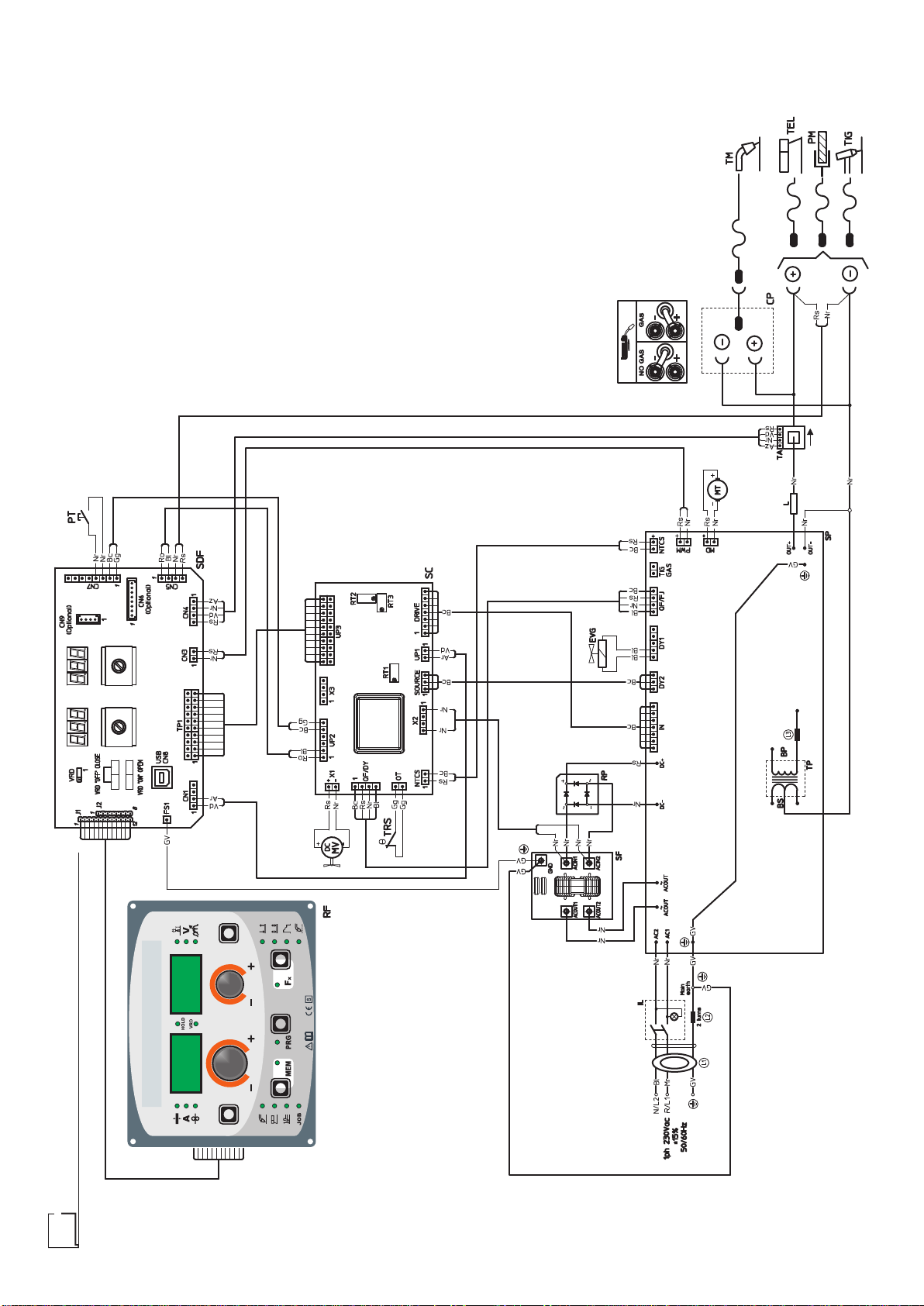
Electro topographical diagram

13
•1•2•3•4•5•6•7•8•9•10 •11
BP BS CP EVG IL LL1-2-3 MT MV PM PT
•12 •13 •14 •15 •16 •17 •18 •19 •20 •21 •22
RF RP SC SDF SF TA TEL TIG TM TP TRS
Electro topographical diagram key
•1 Primary transformer coil •2 Secondary transformer coil •3 Polarity change
terminal board •4 Gas solenoid valve •5 Mains switch •6 Secondary induct-
ance •7 Toroidal ferrite •8 Drive motor •9 Fan motor •10 Earth terminal •11
Torch button •12 Rack panel •13 Primary rectifier •14 Control PCB •15 Dig-
ital interface PCB •16 EMC filter PCB •17 Hall effect transformer •18 MMA
torch •19 TIG torch •20 MIG-MAG torch •21 Main transformer •22 Second-
ary diodes thermostat
Colour key
Ar Orange
Az Sky Blue
Bc White
Bl Blue
Gg Grey
Gl Yellow
GV Yellow-Green
Mr Brown
Nr Black
Ro Pink
Rs Red
Vd Green
Vl Violet
Meaning of graphic symbols on welding power source
System for use in environments with in-
creased risk of electroshock
Product suitable for free circulation in the Eu-
ropean Community
Dangerous voltage
Grounding protection
Positive pole snap-in connector
Negative pole snap-in connector
Warning!
Before using the equipment you should care-
fully read the instructions included in this man-
ual
Danger! Parts moving
It is forbidden to use gloves

14
Control panel
Welding Power Source
Introduction 13
KEYAND KNOB COMMANDS 14
Control panel 14
DISPLAYAND LED INDICATIONS 15
Switching on the welding power source and initial
screen 15
Viewing the software version installed 15
Loading of the wire 16
Special functions “Fx” 16
SETUP Menu 18
FACTORY DEFAULT (FAC) 18
TIMERARC ON 18
TIMER Welding power source ON 18
ERROR LOG 19
TEST 19
Menu SPECIAL FUNCTIONS 20
SAFETY CALIBRATION CODE (SCC) 20
MOTOR CALIBRATION (Mot CAL) 20
ARC LENGTHADJUST 21
SWITCH 21
WATER COOLING MODE 21
PASSWORD 22
BLOCKS 22
SERIAL NUMBER 22
MIG-MAG synergic / MIG pulse / double pulsed MIG 23
1 - WELDING PROCESS SELECTION 23
2 - SELECTION OF WELDING PROGRAMME 23
3 - WELDING MODE SELECTION 24
4 - SPECIAL FUNCTIONS “Fx” SELECTION 24
5 - PRE-SETTING 25
6 - WELDING 25
7 - HOLD 25
MIG-MAG manual 26
1 - WELDING PROCESS SELECTION 26
2 - WELDING MODE SELECTION 26
3 - SPECIAL FUNCTIONS “Fx” SELECTION 26
4 - PRE-SETTING 27
5 - WELDING 27
6 - HOLD 27
Special processes 28
Electrode (MMA) 28
1 - WELDING PROCESS SELECTION 28
2 - SELECTION OF WELDING PROGRAM 28
3 - SPECIAL FUNCTIONS “Fx” SELECTION 29
4 - PRE-SETTING 29
5 - WELDING 29
6 - HOLD 30
7 -ACTIVATING THE VRD DEVICE 30
TIG with “Lift” striking 30
1 - WELDING PROCESS SELECTION 30
2 - SPECIAL FUNCTIONS “Fx” SELECTION 30
3 - PRE-SETTING 31
4 - WELDING 31
5 - HOLD 31
JOB 32
1 - CREATINGAND SAVING A JOB 32
2 - JOB SELECTION 32
3 - PRE-SETTING / VIEWING MEMORISED JOB
DATA 32
4 - WELDING 33
5 - HOLD 33
6 - MODIFICATIONAND OVERWRITING OF A
MEMORISED JOB 33
7 - DELETINGA JOB SAVED 33
Error condition 34
Introduction
This manual contains all the information necessary to make the
best use of this control panel. This control panel is specifically for
multi-process welding power sources: MIG-MAG, PULSED MIG,
DOUBLE PULSED MIG, MMAand TIG.

15
Control panel
KEY AND KNOB COMMANDS
▪ ENCODER knob - V
▪ WELDING MODE
SELECTION key
▪ SPECIAL FUNCTIONS
key “Fx”
▪ PROGRAMME SELECTION key
▪ SET-UP MENU Key
▪ ENCODER knob - A
▪ WELDING PROCESS
SELECTION key
▪ SAVE “MEM” key
▪ PARAMETER
SELECTION key - A ▪ PARAMETER
SELECTION key - V
■PARAMETER SELECTION key - A
This is used to select the following welding parameters:
• THICKNESS OF WELDED ITEM ( ).
• WELDING CURRENT ( ).
• WIRE SPEED ( ).
■ENCODER knob - A
This is used to set and edit the PARAMETERS - A based on the
corresponding LED switched on and the value highlighted on the
DISPLAY PARAMETERS -Adisplay, required for correct function-
ing of the machine.
■PARAMETER SELECTION key - V
This is used to select the following welding parameters:
• ARC LENGTH ADJUSTMENT ( ).
• WELDING VOLTAGE ( ).
• ELECTRONIC INDUCTANCE ( ).
■ENCODER knob - V
This is used to set and edit the PARAMETERS - V based on the
corresponding LED switched on and the value highlighted on the
DISPLAY PARAMETERS - V display, required for correct function-
ing of the machine.
■PROGRAMME SELECTION key
It can be used to select the individual welding PROGRAM for MIG-
MAG and MMAwelding processes.
■SET-UP MENU Key (T > 3 s)
This provides access to the SET-UP menu, which in turn provides
access to a series of functions, suitable for an expert operator.
■WELDING PROCESS SELECTION key
It can also be used to select the following welding processes:
• MIG-MAG / PULSED MIG / Double PULSED MIG.
• MMA.
• TIG.
• JOB.
■SAVE“MEM”key(T≥2s)
It allows the saving of the parameters in the JOB.
It also allows one to view / change the parameters previously saved
in the JOB.
WARNING: No LED switches on when this key is activated!
■WELDING MODE SELECTION key
This is used to select the following welding modes (only for MIG
welding processes) and each time the key is pushed the welding
power source moves on to select the next welding mode in the
following order:
TWO STROKE (2T)
2T LED ( ) switched on
Pressing the TORCH TRIGGER starts the welding cycle, which
will stop when it is released.
FOUR STROKE (4T)
4T LED ( ) switched on
1) Pressing and releasing the TORCH TRIGGER will start the
welding cycle.
2) Pressing and releasing the TORCH TRIGGER will start the
welding cycle.
CRATER 2T
2T LED ( ) switched on - CRATER LED ( ) switched on
1) When theTORCHTRIGGER is pushed the arc ignites and the
parameters assume the values for the “initial crater” for a time
set by means of the CRATER START TIME (F10) function.
After that the parameter values become those for “welding” for
a time defined by the CRATER STARTSLOPE (F11) function.
2) When the TORCH TRIGGER is released the parameters take
on the “final crater” values for a time set by means of the CRA-
TER END TIME (F15) function, for a period of time set using
the CRATER END SLOPE (F12) function.
CRATER 4T
4T LED ( ) switched on - CRATER LED ( ) switched on
1) When the TORCHTRIGGER is pushed the arc ignites and the
parameters assume the values for the “initial crater”.
2) When the TORCH TRIGGER is released the parameters
take on the “welding” values for a time set using the CRATER
START SLOPE (F11) function.
3) When the TORCH TRIGGER is pushed again the parameters
take on the “final crater” values for a time defined using the
CRATER END SLOPE (F12) function.
4) Releasing the TORCH TRIGGER will end the welding cycle.
SPOT WELDING 2T
2T LED ( ) switched on - SPOT LED ( ) switched on
This is used so that on pressing the TORCH TRIGGER spot weld-
ing is done for a time period set beforehand (in seconds), after
which the arc switches off automatically (SPOT WELD TIME F07
function).
STITCH WELDING 2T
2T LED ( ) switched on - SPOT LED ( ) flashing
To begin stitch welding:
1) Press the TORCH TRIGGER to start the welding current and
wire feed.
At this point the welder will perform automatically a succession
of a welded tracts followed by a pause, respecting the times
set in the functions STITCH WELD TIME (F05) and STITCH
WELD PAUSE (F06).
This procedure stops automatically only when the TORCH
TRIGGER is released.
2) When the TORCH TRIGGER is pushed again the torch be-
gins a new interval welding cycle.
SWITCH mode
4T LED ( ) switched on - CRATER LED ( ) flashing
1) When the TORCH BUTTON is pushed, the arc is ignited and
the welding parameters take on the values for the initial cra-
ter.
2) When the TORCH BUTTON is released, the current goes to
that for welding at a time defined by the CRATER START
SLOPE function (F11).
3) When the SWITCH BUTTON is pressed and released within
1 second, the current goes to that defined by the (F19) and
(F20) “SWITCH” functions. By repeating this operation, you
can switch an infinite number of times between the I2 level
and welding level.
4) When the TORCH BUTTON is pushed again and held down
for more than 1 second, after a time defined by the CRATER
END SLOPE (F12) function, the welding parameters taken on
the values for the final crater. When the TORCH BUTTON is
released the welding cycle ends.

16
■SPECIALFUNCTIONSkey“Fx”(T≥2s)
This key is used to display and edit some parameters (ADJUST-
ABLE FUNCTIONS “Fx”) that are necessary and fundamental for
welding and that have already been set by the manufacturer in
the factory.
The parameters vary depending on the welding process and mode
used, and are saved in the memory for each automatic welding
point (JOB).
DISPLAY AND LED INDICATIONS
▪ VRD LED▪ HOLD FUNCTION LED
▪ PARAMETER
SELECTION LED - V
▪ PARAMETER
SELECTION LED - A
▪ PROGRAMME
SELECTION LED
▪ WELDING MODE
SELECTION LED
▪ Fx LED - SPECIAL
FUNCTIONS
▪ WELDING PROCESS
SELECTION LED
▪ JOB SAVING MEM LED
▪ PARAMETER DISPLAY screen - V▪ PARAMETER DISPLAY screen - A
■PARAMETER SELECTION LED - A
When one of these LEDs is on it means that the corresponding
welding parameter has been selected.
■PROGRAMME SELECTION LED
This LED will be lit only when the operator selects a welding pro-
cess (in which there welding programmes present) and the rela-
tive associated programme.
■PARAMETER DISPLAY screen - A
This Display shows the values / numbers (set or measured) of the
following parameters (if active):
• THICKNESS OF WELDED ITEM ( ).
• WELDING CURRENT ( ).
• WIRE SPEED ( ).
• WELDING PROGRAM ( ).
■HOLD FUNCTION LED
Flashing, it indicates that the values of the parameters views on
the PARAMETER DISPLAY -Aand V are respectively the values
that are set or measured at the conclusion of the last welding. The
LED flashes for 15 seconds consecutively before turning itself off or
until the moment that the operator varies any parameter by means
of the use of the handles.
■WELDING PROCESS SELECTION LED
When one of these LEDs is on it means that the corresponding
welding process has been selected.
■PARAMETER SELECTION LED - V
When one of these LEDs is on it means that the corresponding
welding parameter has been selected.
■PARAMETER DISPLAY screen - V
This Display shows the values / numbers (set or measured) of the
following parameters (if active):
• ARC LENGTH ADJUSTMENT ( ).
• WELDING VOLTAGE ( ).
• ELECTRONIC INDUCTANCE ( ).
■JOB SAVING MEM LED
Flashes while saving a JOB.
■Fx LED - SPECIAL FUNCTIONS
Switched on when special Fx parameters are displayed.
■VRD LED
The Voltage Reduction Device (VRD) is a safety device that re-
duces voltage. It prevents voltages forming on the output termi-
nals that may pose a danger to people.
Two-tone LED (off - red - green) indicates enabling of the VRD. In
the welding process:
• MIG MAG (Synergic and Manual) / JOB: the VRD device is not
managed and therefore the LED always will be off.
•
MMA: the operator can decide whether or not to activate the
VRD device (to activate the VRD device see the corresponding
paragraph) based on its necessities and therefore the LED will
be lit and will indicate the activation of the device.
•
TIG Lift: the VRD device is always inserted, independently from
the state of the JUMPER and therefore the LED always will be lit.
■WELDING MODE SELECTION LED
When one or a combination of these LED is lit, it means that the
corresponding manner of welding has been selected.
Switching on the welding power
source and initial screen
At the switching on of the welder (press the switch, located on the
back panel, at the position I), the control performs a short operation
of MACHINE CHECK (all of the LED light themselves simultane-
ously so as to verify their actual operation), and the panel display
the INITIAL SCREEN (see the demonstrative figure), after which
the operator can begin to work.
Viewing the software version installed
1) When the welding power source is working hold down the
WELDING PROCESS SELECTION key (T2) and WELDING
MODE SELECTION key (T3) together for about 2 consecu-
tive seconds.
T2 T3
17
2) On both displays appears a running string that indicates the
VERSION OF THE SOFTWARE installed on the welder.
The rotation of one of the two ENCODER Knobs - A (E1) or
V (E2) by the operator during the display of the string version
software provokes the block (for 1second), on both the dis-
plays, of the movement of the string itself.
E2E1
3) Ending viewing of the software version on the control panel
can come about in 2 different ways:
• Automatically: by waiting for the display time to elapse.
• Manually: by pushing any key.
Loading of the wire
In the MIG-MAG-PULSE-DOUBLE PULSE welding processes,
with the welder in operation, it is possible to load the wire inside
the torch, following this simple procedure:
• Keep the torch button held down.
• After a time of about 2 seconds, the wire begins to load itself at
a constant speed.
•
This operation is also indicated by a message made up of a nu-
merical value for the wire speed, followed by “LoAd” (see figure).
•
Rotate the ENCODER - A (E1) knob to change the wire load-
ing speed.
• To finish the loading of the wire release the torch button.
E1
Special functions “Fx”
To access the SPECIAL FUNCTIONS “Fx” menu, hold the SPE-
CIAL FUNCTIONS “Fx” key (T3) down for at least 3 consecutive
seconds. The Fx LED switches on.
T3
T > 3 s
The special functions allow the operator to regulate further param-
eters, operations and do partial resetting, and are operative, in a
different way, within each welding process.
Table 1 shows the special functions available. Details of the mean-
ing of the columns are as follows:
• FUNCTION column: name of the special function.
•
DISPLAY column: symbol for the special function (message
shown in the PARAMETERS DISPLAY -A screen).
•
FACTORY column: Factory setting for the special function (mes-
sage shown in the PARAMETERS DISPLAY - V screen).
• RANGE column: regulation field for the special function.
•
The last two groups of columns, WELDING PROCESS and
MIG-MAG WELDING MODE indicate the welding process and
mode in which the special function can be selected. Example:
the SPOT WELDTIME function can be selected only when one
is welding in synergistic MIG-MAG-PULSE or manual SPOT
2T mode.
1) Rotate the ENCODER - A knob (E1) to select the SPECIAL
FUNCTION required. Rotate the ENCODER - V knob (E2) to
edit the VALUE for the special function selected.
WARNING: Changes to values are immediately activated (no fur-
ther confirmation is required and they will be displayed immedi-
ately) or, at least they will become active the next time welding is
done. The operator can edit the functions (not the wire speed and
other parameters) when welding is underway and continue weld-
ing without having to exit the SPECIAL FUNCTIONS “Fx” menu.
E2E1
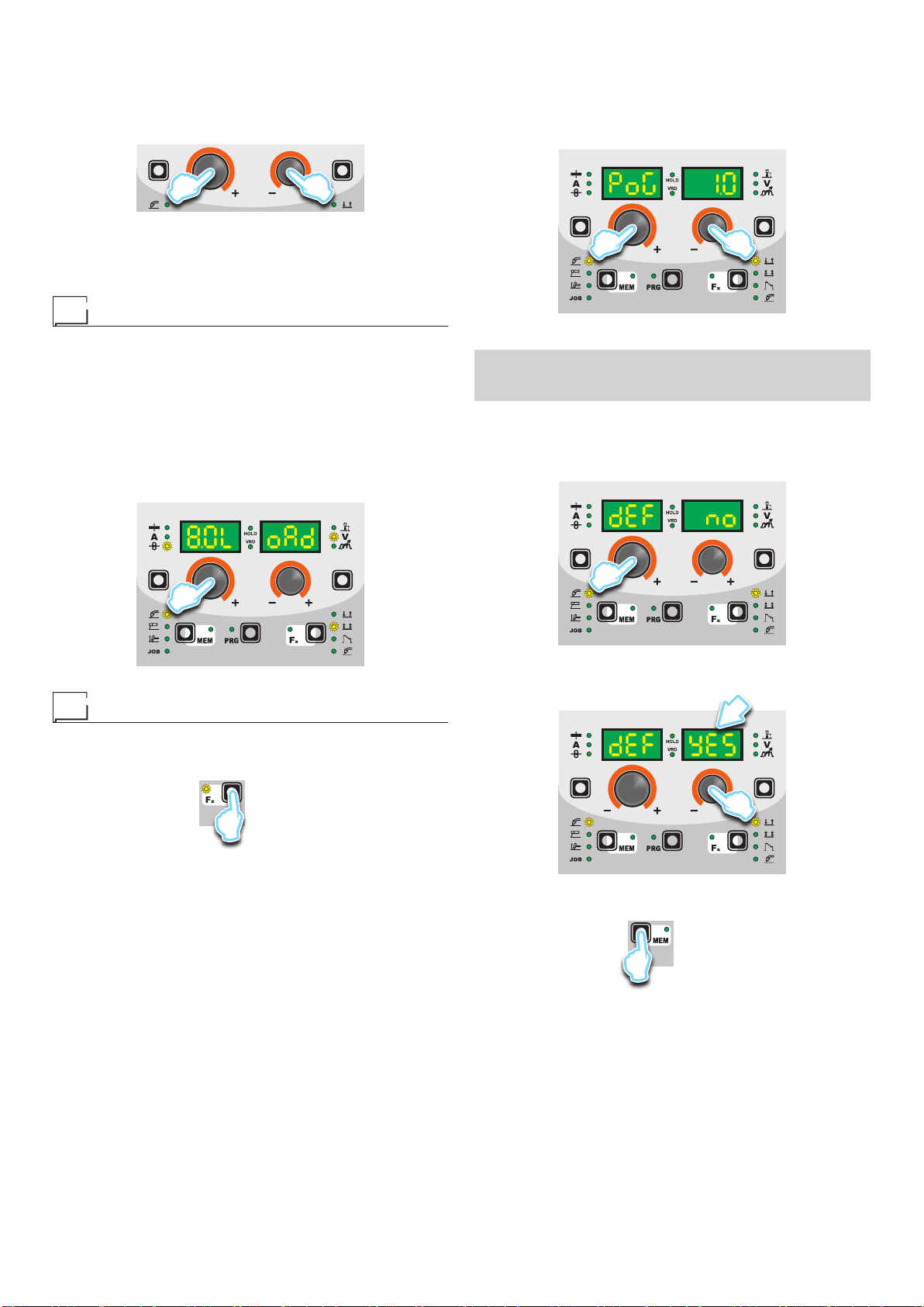
2) PROGRAM DEFAULT (dEF)
WARNING: If carried out, this operation resets the program
in use to the factory default settings.
To carry out the reset of the settings / parameters, proceed in
the following manner:
• Rotate the ENCODER -A (E1) knob until both the displays
read dEF no (see figure).
E1
•
Rotate the ENCODER - V knob (E2) until the PARAME-
TERS DISPLAY - V screen (D2) reads YES.
D2
E2
• Hold the SAVE “MEM” key (T2) down for at least 2consec-
utive seconds.
T2
T ≥ 2 s
• The program in use has now been completed successfully.
To confirmation the above, the control panel of the welder
performs a short operation of MACHINE CHECK (all of the
LED stay lit simultaneously so as to verify their actual op-
eration), the generator itself starts, having memorised the
new settings and is again ready to weld.
18
Table 1
FUNCTION DISPLAY
SETTINGS RANGE WELDING PROCESS MIG-MAG WELDING MODE
FACTORY RANGE
MIG MAG / PULSE
TIG MMA 2T 4T Cra
2T Cra
4T Spot
2T Stitch
2T Cycle
MiG
PLS
CLd dPL MAn SPd
ADJUSTABLE FUNCTIONS “Fx” Fx > 3s
MIG-MAG process
PRE GAS PrG 0.1s (0.0 ÷ 2.0)s ●●●● ●●●●●●●
STARTING SPEED Sts 0-30 ÷ +30 ●●●● ●●●●●●●
HOTSTART Hot 0-30 ÷ +30 ●●●● ●●●●●●●
CRATER
INITIALCRATER
CRATER START CURRENT F08 20% (-50 ÷ +100)% ● ● ● ● ● ●
CRATER START SPEED F08 5.0m/min (1.5 ÷ 22.0)m/min ● ● ● ●
CRATER START VOLTAGE F09 25.0V (10.0 ÷ 38.0/42.0)V ● ● ● ●
CRATER STARTTIME F10 1.0s (0.0 ÷ 20.0)s ●●●● ●
CRATER START SLOPE F11 1.0s (0.0 ÷ 20.0)s ●●●● ●● ●
FINALCRATER
CRATER END SLOPE F12 1.0s (0.0 ÷ 20.0)s ●●●● ●● ●
CRATER END CURRENT F13 -30 (-99 ÷ +50)% ● ● ● ● ● ●
CRATER END SPEED F13 5.0m/min (1.5 ÷ 22.0)m/min ● ● ● ●
CRATER END VOLTAGE F14 25.0V (10.0 ÷ 38.0/42.0)V ● ● ● ●
CRATER END TIME F15 0.0s (0.0 ÷ 20.0)s ●●●● ●
SPOTWELD TIME F07 3.0s (0.1 ÷ 20.0)s ●●●● ●
STITCH WELD
STITCH WELD TIME F05 1.0s (0.1 ÷ 20.0)s ●●●● ●
STITCH WELD PAUSE F06 1.0s (0.1 ÷ 20.0)s ●●●● ●
BURN BACK bUb 0-30 ÷ +30 ●●●● ●●●●●●●
POSTGAS PoG 1.0s (0.0 ÷ 10.0)s ●●●● ●●●●●●●
CYCLE
CYCLE CURRENT F19 20% (-99 ÷ 100)% ● ● ● ●
CYCLE WIRE SPEED F19 5.0 m/min (1.5 ÷ 22.0)m/min ● ●
CYCLEARC LENGTH F20 0-30 ÷ 30 ● ● ● ●
CYCLE VOLTAGE F20 25.0V (10.0 ÷ 38.0/42.0)V ● ●
DUAL PULSE FUNCTIONS
DUALPULSE DELTA CURRENT F23 50% (-99 ÷ +200)% ● ●●●●●●●
DUALPULSE BALANCE F25 0% (-40 ÷ +40)% ● ●●●●●●●
DUALPULSE FREQUENCY F26 2.7Hz (0.1 ÷ 5)Hz ● ●●●●●●●
DYNAMICS dYn 0-30 ÷ 30 ● ●●●●●●●
TIG process
UPSLOPE F29 0.0s (0.0 ÷ 20.0)s ●
DOWN SLOPE F30 2.0s (0.0 ÷ 20.0)s ●
SWS VOLTAGE LIMIT F31 0-30 ÷ 30 ●
MMAprocess
HOTSTART Hot 50 0 ÷ 100 ●
ARC FORCE ArC 50 0 ÷ 100 ●
PROGRAM DEFAULT dEF no no - YES ●●●●●●●●●●●●●
SETUP (SEtUP) menu PRG > 3s
FACTORYDEFAULT FAC no no - YES ●●●●●●●●●●●●●
TIMERARC ON ArC ont ●●●●●●●●●●●●●
TIMER Welding power source ON tiM Eon ●●●●●●●●●●●●●
ERROR LOG Err Log ●●●●●●●●●●●●●
TEST tES t ●●●●●●●●●●●●●
SPECIAL FUNCTIONS (SPC FnC) menu PRG > 3s
SAFETY CALIBRATION CODE SCC 70 ÷ 100 ●●●● ●●●●●●●
MOTOR CALIBRATION Mot CAL
SPEED MOTOR 1 SM1 75.0 50.0 ÷ 99.9 ●●●● ●●●●●●●
SPEED MOTOR 2 SM2 75.0 50.0 ÷ 99.9 ●●●● ●●●●●●●
SPEED MOTOR 3 SM3 75.0 50.0 ÷ 99.9 ●●●● ●●●●●●●
ARC LENGTHADJUST ArC UU - rPM ●●●● ●●●●●●●
CYCLE CYC oFF oFF - on ●●●● ●●●●●●●
WATER COOLING MODE H2o Dem Dem - Aon ●●●●●●●●●●●●●
PASSWORD PAS 00 ÷ 999 ●●●●●●●●●●●●●
BLOCKS bLC no no - L1 - L2 - L3 ●●●●●●●●●●●●●
SERIAL NUMBER SEr nUM ●●●●●●●●●●●●●

19
3) To exit the SPECIAL FUNCTIONS “Fx” menu, push and re-
lease the SPECIAL FUNCTIONS “Fx” (T3) key once.
T3
SETUP Menu
Hold the PRG key down for at least 3 seconds to open the SET-
UP menu, which provides access to various functions, which are
suitable for expert operators, such as advanced configurations,
system tests, and calibrations. For further information, see table 1.
FACTORY DEFAULT (FAC)
WARNING: If carried out, this operation results in complete
resetting of all editable parameters to the factory settings (in-
cluding cancellation of the JOBS).
To carry out the reset of the settings / parameters, proceed in the
following manner:
1) Rotate the ENCODER - A (E1) knob until both the displays
read FAC no (see figure).
E1
2) Rotate the ENCODER - V knob (E2) until the PARAMETERS
DISPLAY - V screen (D2) readsYES.
D2
E2
3) Hold the SAVE “MEM” key (T2) down for at least 2consecu-
tive seconds.
T2
T ≥ 2 s
4) At this stage the total reset or factory default procedure has
been completed successfully (the parameters have been tak-
en back to the factory values and any JOBS saved have been
deleted). To confirmation the above, the control panel of the
welder performs a short operation of MACHINE CHECK (all
of the LED stay lit simultaneously so as to verify their actual
operation), the generator itself starts, having memorised the
new settings and is again ready to weld.
TIMER ARC ON
This indicates the actual time the machine was used for welding.
WARNING: This time can only be zeroed using the FACTORY DE-
FAULT (FAC in the SEtUP menu) for the welding plant.
1) Rotate the ENCODER - A (E1) knob, until both the displays
(D1-D2) read ArCont.
D1 D2
E1
2) Push the PRG key to view the welding use time, expressed in
DAYS (d), HOURS (H), MINUTES (M). Example: 2d-3H-25M.
3) To go back to the SEtUP menu, push the SAVE “MEM” (T2)
key.
T2
TIMER Welding power source ON
This indicates the time the welding power source was switched on.
WARNING: This time can only be zeroed using the FACTORY DE-
FAULT (FAC in the SEtUP menu) for the welding plant.
1) Rotate the ENCODER - A (E1) knob, until both the displays
(D1-D2) read tiMEon.
D1 D2
E1
2) Push the PRG key to view the time the welding power source
was switched on, expressed in DAYS (d), HOURS (H), MIN-
UTES (M). Exam-ple: 120d-13H-22M.
3) To go back to the SEtUP menu, push the SAVE “MEM” (T2)
key.
T2
20
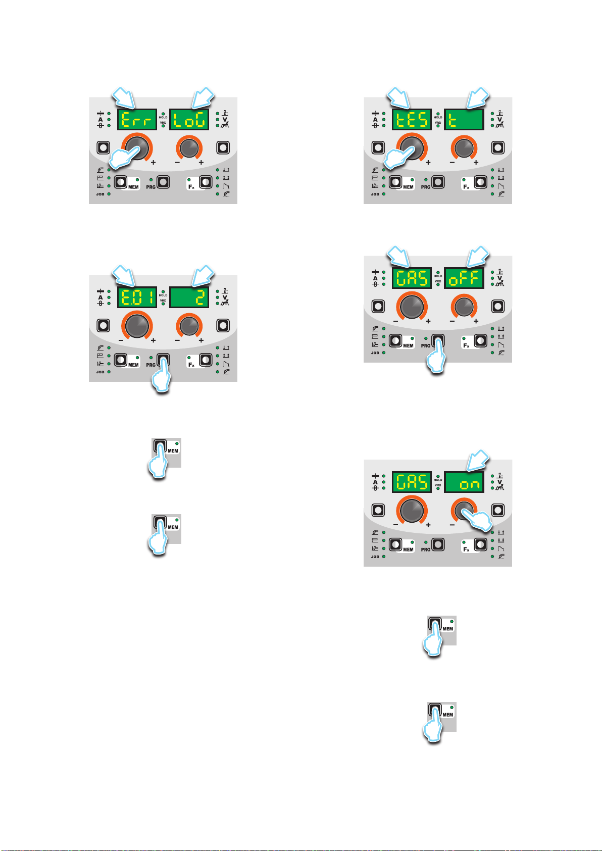
ERROR LOG
This allows the operator to know about the error states that have
arisen on the welding plant.
1) Rotate the ENCODER - A (E1) knob, until both the displays
(D1-D2) read Err Log.
D1 D2
E1
2) Push the PRG key (T5), and the display will show the error
code under DISPLAY PARAMETERS -A (D1), and the num-
ber of times under DISPLAY PARAMETERS - V (D2). For the
code error, see the list contained in the “Error Conditions” par-
agraph.
D1 D2
T5
3) Rotate the ENCODER - V (E2) knob to scroll the list.
4) To go back to the SEtUP menu, push the SAVE “MEM” (T2)
key.
T2
5) To exit the SEtUP menu, push the SAVE “MEM” (T2) key
again.
T2
TEST
This configuration allows the operator to check that some func-
tions of some devices.
1) Rotate the ENCODER - A (E1) knob, until both the displays
(D1-D2) read tESt.
D1 D2
E1
2) Push the PRG key (T5), and the display will show the param-
eter to be checked under DISPLAY PARAMETERS - A (D1),
and the set-ting under DISPLAY PARAMETERS - V (D2).
D1 D2
T5
3) Rotate the ENCODER -A(E1) knob to select the device to be
tested, from GAS (solenoid valve), Mot (wire feeder motor),
FAn (fans) and H2o (cooling unit, only if fitted).
4) Rotate the ENCODER - V (E2) knob clockwise to go from the
oFF state to the on state, which activates the device and al-
lows the user to check it is working.
D2
E2
5) To go back to the oFF state, rotate the ENCODER - V (E2)
knob anticlockwise.
6) Push the SAVE “MEM” (T2) key to go back to the SEtUP
menu.
T2
7) To check another device, repeat steps 2, 3 and 4.
8) To exit the SEtUP menu, push the SAVE “MEM” (T2) key
again.
T2
Other manuals for DIX GO 1156.M Puls
1
Table of contents
Other DINSE Welding System manuals


