LORCH
5 General regulation
of
use
This machine is intended for use in the commercial and
industrial sector. It is portable and is suitab
le
for opera-
tion on the mains supply or also on a power generator.
D The machine is intended for DC electrode welding
of
-una
ll
oyed steels, low and high-alloy steels,
-
ni
ckel and its alloys,
D Together with a T
IG
welding tor
ch
. the machine is
suitable for TIG
we
lding with direct current
of
-unalloyed st
ee
ls, low and high-alloy steels,
-copper and its alloys,
- nickel and its alloys,
-special metals like titani
um
, zirconium and tanta-
lum.
D Together with a
wi
re feed case, the machine is suit-
able for MIG welding with
-solid wire
(M
IG/MAG),
flux-cored wire.
6
UW
inspection
Operators
of
commercially-operated welding systems
are obliged to have regular safety inspections
of
t
he
equipment carried out in accordance with EN 60974-4.
Lorch recommends inspections
al
12 month intervals.
A safety i
ns
pection must also
be
car
ri
ed out if
mod
ifica-
tions or repairs have been made to the system.
G Improper
UW
inspections can destroy the
system. For more information on UVV
in
-
spections
of
welding systems, please con-
tact your authorised Lorch service centre.
7 Unit protection
This machine is protected electronically against over-
loading. Do not use fuses
of
higher amperage than print-
ed on the identification plate.
8
Noise
emissi
on
The noise level
of
the unit is less than 70 dB(A}, meas-
ur
ed
under standard load
in
accordance with EN 60974-
1
in
the maximum
wo
rking poin
t.
- 6 -
Trans
port
9 Electromagnetic compatibility
(EMC)
This product is manufactured
in
conformance with the
current EMC standard. Please note the followin
g:
D Due to their high power consumption, weldi
ng
ma
-
chines can cause problems in t
he
public power grid.
The mai
ns
connection is therefore subject to requi
re-
ments with regard to the maximum permissible sys-
tem impedance. The maximum permissible system
impedance (Zmax)
of
the interface to the power grid
(mains
con
nection) is
in
dica
ted
in the tec
hn
ical data.
If
in
doubt, please contact your power grid operator.
D The machine is intended forwe
ld
ing
in
both commer-
cial and industrial applications
(C
ISPR
11
cl
ass A).
Use in other surroundings (for example
in
residential
areas)
may
disturb otherelectronic devices.
D Electromagnetic problems during start-up can arise
i
n:
-Mains cables, control cables, signal and telecom-
municat
io
n lines near the weldi
ng
or cutting area
-TV/radio transmitters/receivers
-Computers and other control devices
- Protection equipment such as alarm systems
-Pacemakers and hearing ai
ds
-Measurement and calibration devices
-Equipment with too little protection against inter-
ference
If other equipment is disturbed, it may
be
necessary to
provide additional shie
ld
in
g.
D The affected area may go beyond the boundaries of
the property concerned. This depends on the layout
of the
bu
ildi
ng
, and the other activities that may
be
going on the
re
.
Please u
se
the mac
hi
ne
in
compliance with the manu-
facturer's instructions. The operator of the equipment is
responsible for the installation and use
of
the machine.
Furthe
rm
ore, the owner is
re
sponsible (if necessary w
it
h
technical assistance from the manufacturer) for eliminat-
i
ng
the interference caused by e
le
ctromagnetic fiel
ds
.
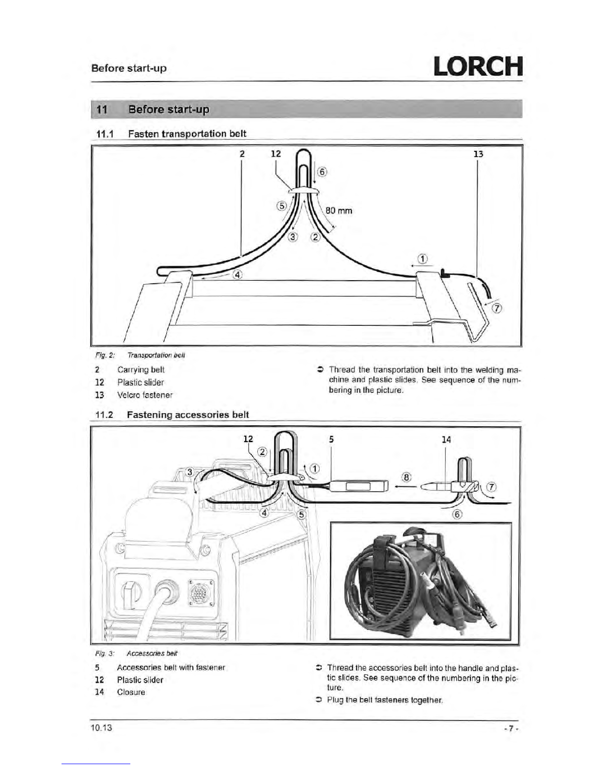
10 Transport
For
tran
spo
rt
usi
ng
mec
hanical l
iftin
g
gear (e.g. cranes etc.) o
nl
y the handle
may be
us
ed as the
hoi
s
ting
p
oin
t. Use
suitable loa
d-
bear
in
g e
qu
ipment.
Do
no
t
us
e a
for
k-
l
ift
1r
uck
or
s
im
ilar
de-
vice
to
li
ft
the
mach
ine
by
its
housing.
The c
ar
rying
st
rap
is
exc
lu
sive
ly
for
the
transpo
rt
by a pe
rson
.
10.
13