Operating Manual MSA 160
MSA 160 Ver. 1.00
SN: S182Z6605010
230V 50Hz
01/04/17 12:12
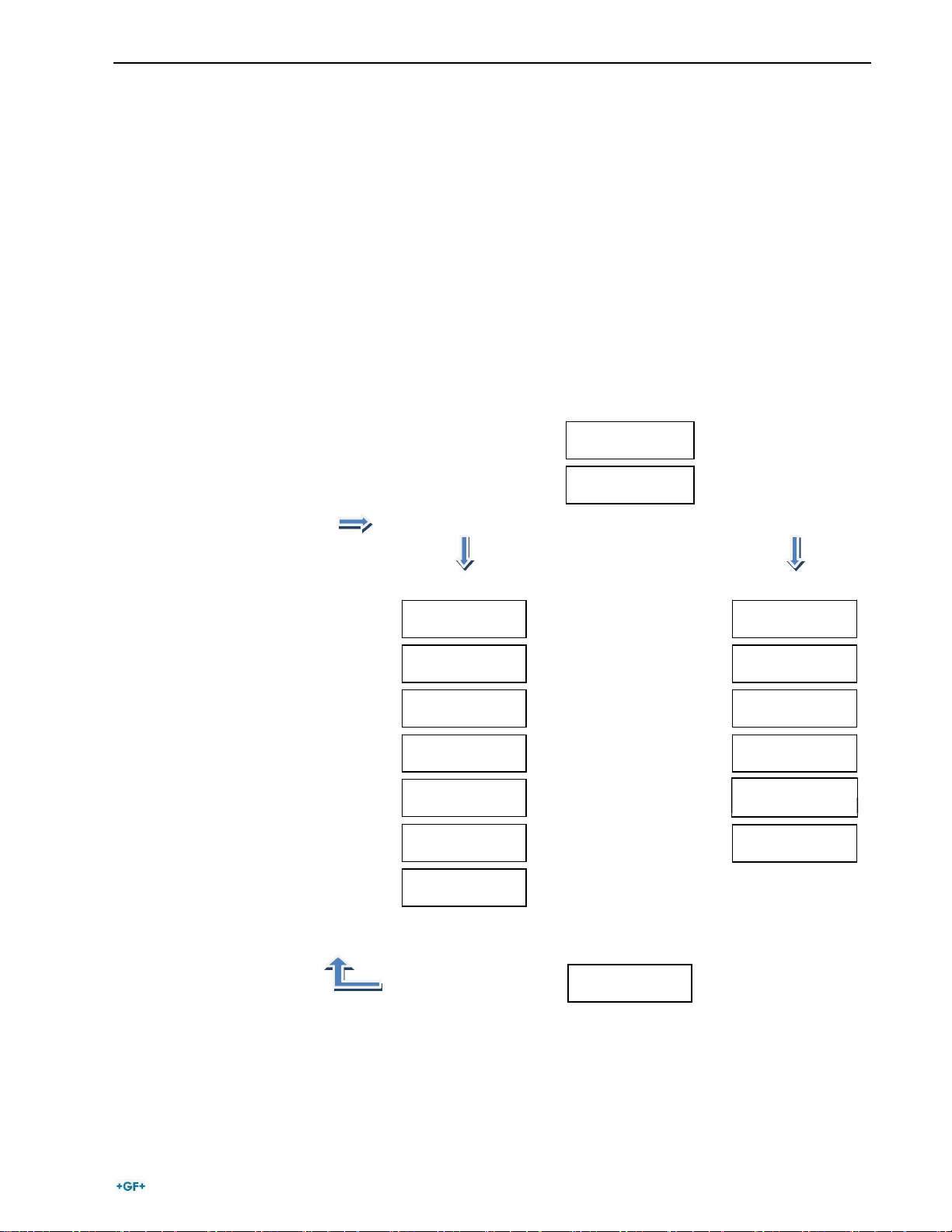
2.2 Power On
Connect the machine to the power mains or power generator, already
started, and switch on the machine. The display shows the information
concerning the installed software and the serial number of the
machine.
Then it shows the input voltage and frequency
At this time you may change some settings of the unit: date/time,
language or brightness of the display itself (see “Settings” paragraph).
Make sure that the frequency value is in the range 50 – 60 Hz and the
voltage is between 205 – 255 V. Then press START to go ahead.
PEEL & CLEAN?
YES=START
Advise
ENTER FUSION
DATA
GF I 110 mm
40 V 210 sec
2.3 Fusion data entry
The MSA 160 allows the manual insertion of the parameters or the
automatic acquisition, if the scanner is used, by reading the barcode
data of the fitting.
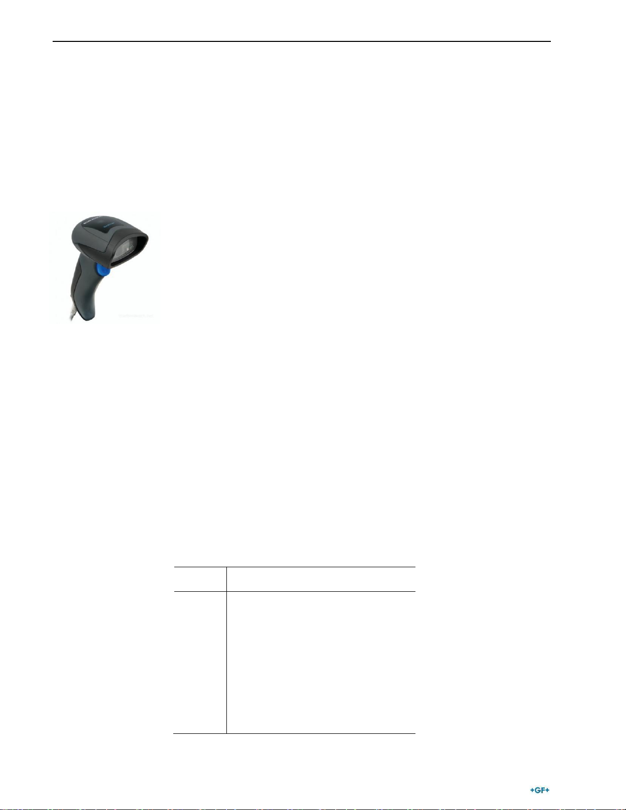
If the scanner is available and connected to the USB port, the MSA 160
will switch to barcode mode.
If not, it will allow the input of values manually (see next paragraphs for
the detailed explaination).
2.3.1 Bar code data input (optional)
Pipes preparation
If the pipes are scraped and cleaned press START; otherwise get
back and do the fusion preparations.
The preparation of the pipes according to guidelines (scraping, cleaning,
alignment) is essential to ensure the quality of the welding.
Data entry
If the scanner is connected, the next message will ask to ENTER FUSION
DATA, coded on the sticker of the connected fitting.
Only fittings with a diameter ≤ 160 will be accepted by the MSA160. For
larger diameters a message will pop up on the display, alerting the user.
When the data are captured, the display will switch automatically to a
different view, summarizing the parameters printed in the barcode.
If the barcode is not read, try once again, taking care of the
suggestions mentioned in the previous chapter.
8