Diodes AP3154FG-EVM User manual

AP3154A Evaluation Module
120mA HIGH EFFICIENCY WHITE LED DRIVER
A
P3154FG-EVM Rev.1 1 of 4 MARCH 2011
www.diodes.com © Diodes Incorporated
•V
IN Range: 2.7V to 5.5V
•Up to 88% Maximum Power Efficiency
•1X, 1.5X and 2X Charge Pump Modes
•Drives up to Four White LEDs
•120mA Maximum Total Output Current
•Programmable Switching Frequency (Default
1.2MHz)
•Spread Spectrum Control with 10% Frequency
Deviation
•1-Wire Serial Digital Interface or PWM Dimming
Control
•Soft-Start During Power-up and Mode Switching
•Soft-Stop During Shutdown
•Short-Circuit Protection
•Over-Voltage Protection and Under-Voltage
Lockout
•IQ <6μA in Shutdown
•Thermally-Enhanced QFN3030-12 Package:
Available in “Green” Molding Compound (No Br,
Sb)
•Lead Free Finish / RoHS Compliant
The AP3154A is a high efficiency charge-pump white
LED driver with 1x, 1.5x and 2x operating modes. It
operates on power supplies from 2.7v to 5.5v and
can drive up to four channels of white LEDs while the
current of each channel can be individually set to up
to 30mA current. By ganging four channels together it
can provide a maximum load current of 120mA.
The Serial Digital Interface (SDI) provides the
capability to configure the current for each LED
channel. Some other key features, such as Up
Spread Spectrum Control, different charge-pump
switching frequencies (0.6MHz/1.2MHz/1.8MHz), and
PWM dimming control, can also be programmed
through the interface.
The AP3154A has a built-in soft-start circuit to
minimize the inrush current during power-up and
mode switching. Various protections such as
short-circuit, over-voltage, under-voltage and thermal
shutdown are all integrated to ensure system
reliability. The quiescent current of AP3154A during
shutdown is less than 6μA.
Device Package Code Packaging EVM Part Number
AP3154AFG FG QFN3030-12 AP3154FG-EVM
Features Description
Ordering Information
AP3154A Evaluation Module
120mA HIGH EFFICIENCY WHITE LED DRIVER
A
P3154FG-EVM Rev.1 2 of 4 MARCH 2011
www.diodes.com © Diodes Incorporated
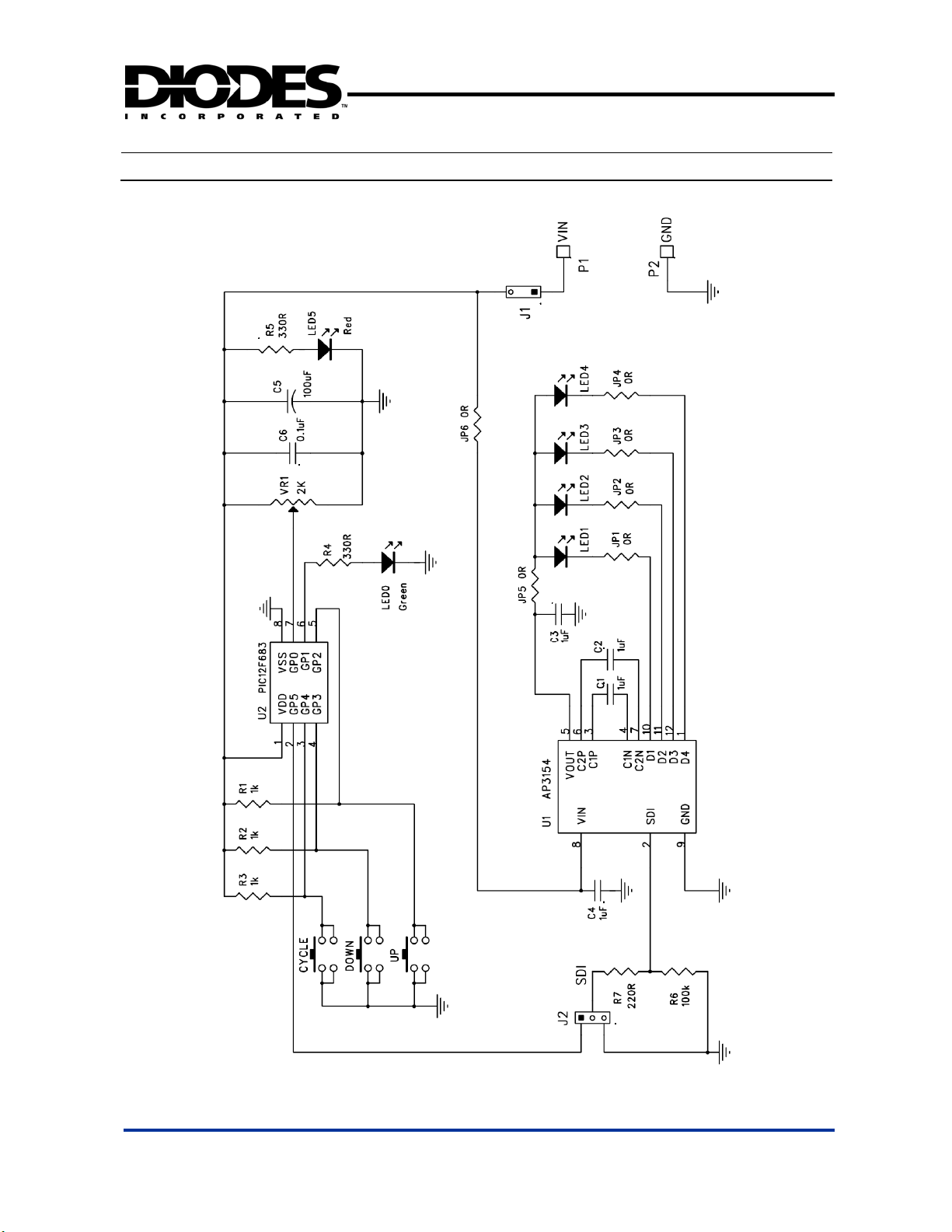
Schematic

AP3154A Evaluation Module
120mA HIGH EFFICIENCY WHITE LED DRIVER
A
P3154FG-EVM Rev.1 3 of 4 MARCH 2011
www.diodes.com © Diodes Incorporated
Bill of Material
Bill of Material for AP3154FG-EVM
Ref Count Size Mfr Part Number Description
P1, P2 2 0.091” STD Keystone Turret headers
J1, J2 2 0.1” STD STD 0.1” x2 headers and jumpers
JP1-JP4 4 0603
STD STD
0 Ωresistor/jumper
JP5, JP6 2 0805 STD STD
0 Ωresistor/jumper
C1-C4 4 0805 STD STD 1 µF/10V ceramic capacitors
C7 1 TH STD STD 100 µF electrolytic capacitor
R1-R3 3 0805
STD STD
1 kΩresistors
R4, R5 2 0805 STD STD
330 Ωresistors
R6 1 0805
STD STD
100 kΩresistor
R7 1 0805
STD STD
220 Ωresistors
LED1-LED4 4 0805 STD STD
White LEDs
LED0 1 TH
STD STD
Green LED
LED5 1 TH
STD STD
Red LED
CYCLE,
DOWN, UP 3 Omron B3F-1022
Tactile push buttons
VR4 1
Bourns 3362R
2 kΩpotentiometer
U1 1 SOP8
Diodes AP3154A
Four-channel WLED driver
U2 1 SOP8
Microchip PIC12F683 8-bit microcontroller
I/O Terminals and Test Points
Terminals and Jumpers for AP3154FG-EVM
I/O and Test Points Description Comments
P1 (VIN), P2 (GND) Power Supply and Ground Connect to input power supply
J1 Power Supply Jumper Jumper for connecting VIN to the AP3154A
J2 SDI Connecter/Jumper Select onboard or external SDI signal

AP3154A Evaluation Module
120mA HIGH EFFICIENCY WHITE LED DRIVER
A
P3154FG-EVM Rev.1 4 of 4 MARCH 2011
www.diodes.com © Diodes Incorporated
Quick Start Guide
1. Insert jumper J1 to connect VIN to the AP3154A and the onboard SDI controller. Also insert a
jumper on J2 to use the onboard controller to send SDI commands to the AP3154A.
2. Connect a +2.7V~+5.5V power supply between VIN (P1) and GND (P2) terminals. Turn on the
power supply. The red power indicator LED (LED5) will be on.
3. The SDI controller will enter State 3, where SDI commands are sent to the AP3154A to set the
current levels of all four channels. All four white LEDs will be dimming from bright to dark and from
dark to bright. The following table shows the SDI controller States and associated SDI commands.
4. Press the CYCLE button to change the SDI controller state to the next state. Every time the SDI
controller enters a new state between States 3 and 10, the corresponding LED(s) will be dimming
automatically while the other LEDs will stay at the current levels set in the previous States. Adjust
VR4 to change the repetition rate at which the LEDs are auto-dimmed.
5. While in any state between State 3 and State 10, press the UP or DOWN button to stop
auto-dimming. Then use the UP button to manually increase the current level of the LED(s) and
DOWN button to decrease it. Press the CYCLE button again to resume auto-dimming.
6. Press the CYCLE button while in State 10 will bring the SDI controller to State 1, where the
AP3154A’s switching frequency can be set by using the UP and DOWN buttons. The green LED
(LED0) will flash slowly for lower switching frequency and faster for higher switching frequency.
7. Press the CYCLE button while in State 1 will advance to State 2, where the maximum LED current
can be selected by using the UP and DOWN buttons.
8. Press and hold the CYCLE button at any time will force the SDI controller to enter State 0 and
disable the AP3154A. In this state, all white LEDs (LED1-4) will be turned off. So will the green
LED (LED0). Press the CYCLE button in State 0 will move the SDI controller to State 1.
9. If an external SDI controller is to be used, remove the jumper on J2 and connect the external SDI
signal to between the pin 2 of J2 and GND.
Table: SDI Controller Machine States
SDI
Controller
State
Green
LED
(LED0)
First
SDI
Command
Other
SDI
Commands Description
0 Off - -
Reset: 1) 1.2MHz switching frequency
2)20mAMaxCurrent
3)AllChannelsturnoff
1 Flashing
18
19
20
-
Switching frequency set to 0.6MHz
Switching frequency set to 1.2MHz (default)
Switching frequency set to 1.8MHz
2 On
13
14
15
16
-
2mA Low-Current Mode
14mA Current Mode
20mA Current Mode (default)
30mA Current Mode
3 On 5 1 or 2* Set current level for all 4 Channels
4 On 6 1 or 2* Set current level for CH2, CH4
5 On 7 1 or 2* Set current level for CH1, CH2
6 On 8 1 or 2* Set current level for CH3, CH4
7 On 9 1 or 2* Set current level for CH1
8 On 10 1 or 2* Set current level for CH2
9 On 11 1 or 2* Set current level for CH3
10 On 12 1 or 2* Set current level for CH4
*Note: Use command 1 for increasing current and command 2 for reducing current.
Other Diodes Control Unit manuals


