Diodes AP3156FVG User manual

AP3156 Evaluation Module
HIGH EFFICIENCY CHARGE PUMP WHITE LED DRIVER
A
P3156FVG-EVM Rev.1 1 of 5 OCTOBER 2009
www.diodes.com © Diodes Incorporated
•V
IN Range: 2.7V to 5.5V
•Fully Programmable Current with Single Wire
- 32-Step Logarithmic Scale
- 20/25mA Max Current per Channel
- Four Low Current Settings Down to 50μA
- Low IQ (50μA) for Low Current Mode
•Tri-Mode 1X, 1.5X, and 2X Charge Pump for
Maximum Efficiency and VFCoverage
•Drives up to Six Channels of LEDs
•Individual Main/Sub-Group Control
•No Inductors, Low Noise Operation
•0.5/1/2MHz Constant Switching Frequency
•Built-In Thermal Protection
•Built-In Auto-Disable For Open Circuit
•Automatic Soft Start
•IQ <1μA in Shutdown
•Thermally-Enhanced QFN4040-16 Package:
Available in “Green” Molding Compound (No Br,
Sb)
•Lead Free Finish / RoHS Compliant
The AP3156 is a low noise, constant frequency
charge pump DC/DC converter that uses a tri-mode
(1X, 1.5X and 2X) conversion to maximize efficiency
for white LED applications. It is capable of driving
LEDs at a total of 120mA maximum from a 2.7V to
5.5V input. The six channels may be operated
individually or in parallel for driving higher-current
LEDs.
A low external parts count (two 1μF flying capacitors
and two small 1μF capacitors at VIN and VOUT) makes
this device ideally suited for small, battery-powered
applications. A serial digital input is used to enable,
disable and set current for each LED with a 32-level
logarithmic scale plus four low-current settings down
to 50μA for optimal efficiency, with a low quiescent
current of only 50μA. Each output of the AP3156 is
equipped with built-in protection for VOUT short circuit
and auto-disable for LED failure conditions. Built-in
soft-start circuitry prevents excessive inrush current
during start-up. A shutdown feature disconnects the
load from VIN and reduces quiescent current to less
than 1μA.
Device Package Code Packaging EVM Part Number
AP3156FVG FV QFN4040-16 AP3156FVG-EVM
Features Description
Ordering Information

AP3156 Evaluation Module
HIGH EFFICIENCY CHARGE PUMP WHITE LED DRIVER
A
P3156FVG-EVM Rev.1 2 of 5 OCTOBER 2009
www.diodes.com © Diodes Incorporated
Schematic
AP3156 Evaluation Module
HIGH EFFICIENCY CHARGE PUMP WHITE LED DRIVER
A
P3156FVG-EVM Rev.1 3 of 5 OCTOBER 2009
www.diodes.com © Diodes Incorporated
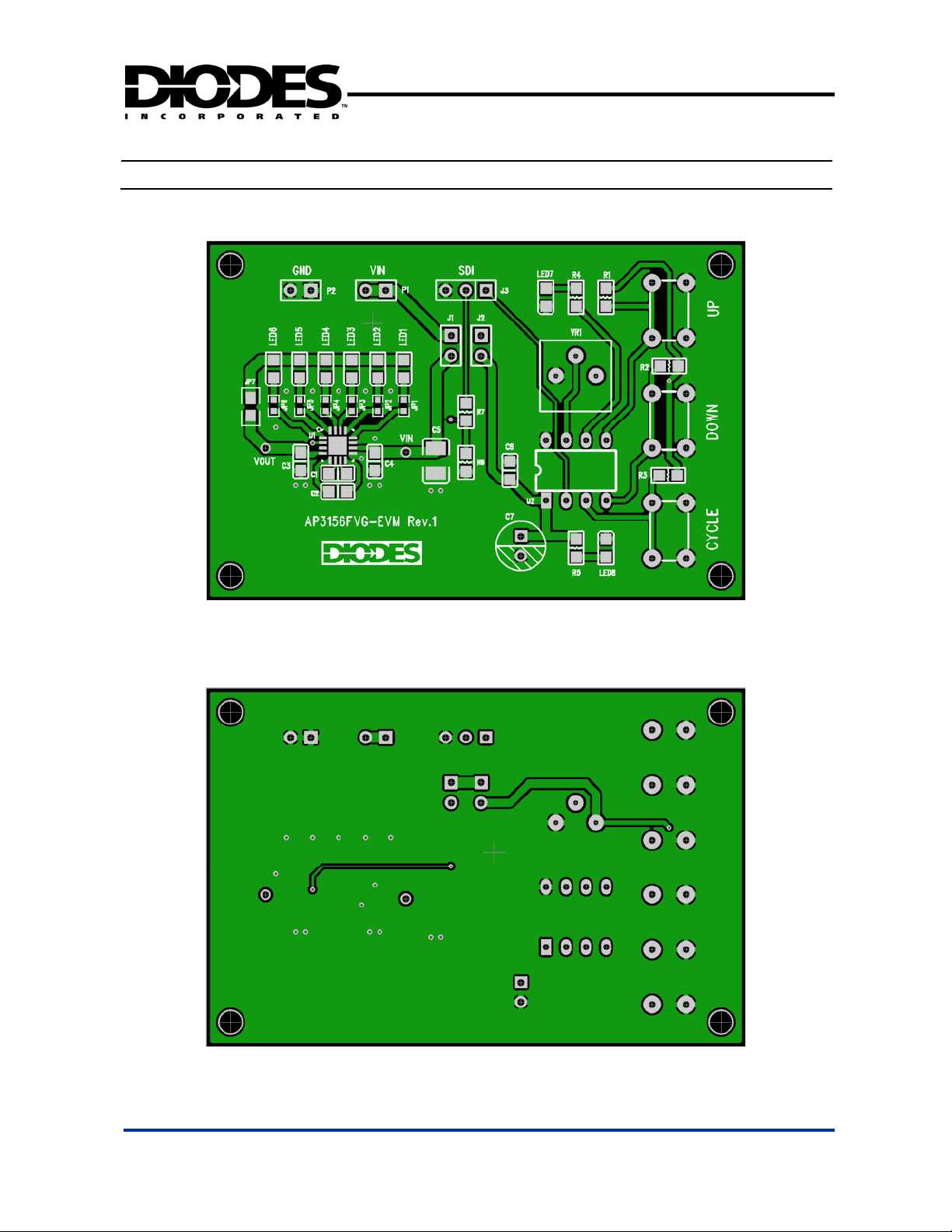
Top Layer Layout of AP3156FVG-EVM
Bottom Layer Layout of AP3156FVG-EVM
PCB Layout

AP3156 Evaluation Module
HIGH EFFICIENCY CHARGE PUMP WHITE LED DRIVER
A
P3156FVG-EVM Rev.1 4 of 5 OCTOBER 2009
www.diodes.com © Diodes Incorporated
Bill of Material
Bill of Material for AP3156FVG-EVM
Ref Count Size Mfr Part Number Description
P1, P2 2 0.1” STD STD 0.1” x2 headers
J1, J2 2 0.1” STD STD 0.1” x2 headers and jumpers
J3 1 0.1” STD STD 0.1” x3 header and jumper
JP1-JP6 6 0603
STD STD
0 Ωresistor/jumper
JP7 1 0805
STD STD
0 Ωresistor/jumper
C1-C4 4 0805 STD STD 1 µF/10V ceramic capacitors
C5 1 1210 STD STD 10 µF ceramic capacitor
C6 1 0805 STD STD 0.1 µF ceramic capacitor
C7 1 TH STD STD 100 µF electrolytic capacitor
R1-R3 3 0805
STD STD
1 kΩresistors
R4, R5, R7 3 0805 STD STD
330 Ωresistors
R6 1 0805
STD STD
100 kΩresistor
LED1-LED6 6 0805 STD STD
White LEDs
LED7 1 0805
STD STD
Green LED
LED8 1 0805
STD STD
Red LED
CYCLE,
DOWN, UP 3 Omron B3F-1022
Tactile switches
VR1 1
Bourns 3362R
2 kΩpotentiometer
U1 1 SOP8
Diodes AP1212xSG
Dual-channel USB power switch
U2 1 SOP8
Microchip PIC12F683 8-bit microcontroller
I/O Terminals and Test Points
Terminals and Jumpers for AP3156FVG-EVM
I/O and Test Points Description Comments
P1 (VIN), P2 (GND) Power Supply and Ground Connect to input power supply
J1 Input Jumper to AP3156 Jumper for connecting VIN to the AP3156
J2 Input Jumper to SDI Jumper for connecting VIN SDI controller circuit
J3 SDI Connecter/Jumper Select onboard or external SDI signal
VIN, VOUT Voltage Test Points Input and output voltage test points

AP3156 Evaluation Module
HIGH EFFICIENCY CHARGE PUMP WHITE LED DRIVER
A
P3156FVG-EVM Rev.1 5 of 5 OCTOBER 2009
www.diodes.com © Diodes Incorporated
Quick Start Guide
1. Insert jumper J1 to connect VIN to the AP3156 and J2 to connect VIN to the onboard SDI controller.
Also insert a jumper between pin 1 and pin 2 of J3 to use the onboard controller to send SDI
commands to the AP3156.
2. Connect a +2.7V~+5.5V power supply between VIN (P1) and GND (P2) headers. Turn on the
power supply. The red power indicator LED (LED8) will be on.
3. The SDI controller will enter State 3, where SDI commands are sent to the AP3156 to set the
current levels of all six channels. All six white LEDs will be dimming from bright to dark and from
dark to bright. The following table shows the SDI controller States and associated SDI commands.
4. Press the CYCLE button to change the SDI controller state to the next state. Every time the SDI
controller enters a new state between States 3 and 14, the corresponding LED(s) will be dimming
automatically while the other LEDs will stay at the current levels set in the previous States. Adjust
VR1 to change the repetition rate at which the LEDs are auto-dimmed.
5. While in any state between State 3 and State 14, press the UP or DOWN button to stop the
auto-dimming. Then use the UP button to manually increase the current level of the LED(s) and
DOWN button to decrease it. Press the CYCLE button again to resume auto-dimming.
6. Press the CYCLE button while in State 14 will bring the SDI controller to State 1, where the
AP3156’s switching frequency can be set by using the UP and DOWN buttons. The green LED
(LED7) will flash slowly for lower switching frequency and faster for higher switching frequency.
7. Press the CYCLE button while in State 1 will advance to State 2, where the maximum LED current
can be set by using the UP and DOWN buttons.
8. Press and hold the CYCLE button at any time will force the SDI controller to enter State 0 and
soft-reset the AP3156. In this state, all white LEDs (LED1-6) will be turned off. So will the green
LED (LED7). Press the CYCLE button in State 0 will change the SDI controller state to State 1.
9. If an external SDI controller is to be used, remove the jumper on J3 and connect the external SDI
signal to between pin 2 and pin 3 (GND) of J3. The jumper on J2 can also be removed.
Table: SDI Controller Machine States
SDI
Controller
State
Green LED
(LED7) First
SDI
Sequence
Second
SDI
Sequence Description
0 Off 33 -
Soft Reset: 1) 1MHz switching frequency
2) 20mA Constant Current Mode
3) All Channels in Current Level 32 (0mA)
1 Flashing 8
1
2
3
Switching frequency selected to 0.5MHz
Switching frequency selected to 1MHz (default)
Switching frequency selected to 2MHz
2 On 9
2
1
3
2mA Low Current Mode, 4 current levels supported
20mA Current Mode, 32 levels supported (default)
25mA Current Mode, 32 current levels supported
3 On 10 1~32* Set current level for all 6 Channels
4 On 11 1~32* Set current level for CH1, CH2, CH3
5 On 12 1~32* Set current level for CH4, CH5, CH6
6 On 13 1~32* Set current level for CH1, CH2, CH3, CH4
7 On 14 1~32* Set current level for CH5, CH6
8 On 15 1~32* Set current level for CH1, CH2, CH3, CH4, CH5
9 On 16 1~32* Set current level for CH6
10 On 17 1~32* Set current level for CH5
11 On 18 1~32* Set current level for CH4
12 On 19 1~32* Set current level for CH3
13 On 20 1~32* Set current level for CH2
14 On 21 1~32* Set current level for CH1
*Only 1~5 in Low Current Mode.
This manual suits for next models
1
Table of contents
Other Diodes Control Unit manuals

Popular Control Unit manuals by other brands


Grundfos
Grundfos MIXIT Integration guide

Honeywell Home
Honeywell Home H600A installation instructions

Synthesis Technology
Synthesis Technology MOTM-510 The WaveWarper Assembly instructions & owner's manual

Inkel
Inkel IRG-8116 Operation manual

ABNOX
ABNOX AXDV-C3-HG Instructions for use

Dantel
Dantel 46017 Installation & operation manual


