Dion-Ag Scorpion 2430 User manual

Operator’s Manual
FORAGE HARVESTER
Manual no. F6918E998E
v1.5

2

3
FOREWORD
We thank you for your confidence towards DION-Ag Inc. agricultural equipment. We have prepared this manual with care
and attention and have designed it as an essential tool that will allow you to use and maintain your machine adequately
and safely. By following the instructions that it contains, you will obtain optimal performance and durability of the
harvester for years to come.
Carefully read this manual in order to familiarize yourself with the adjustment procedures and operation, before
attempting to use the machine. Keep in mind this machine has been designed and tested to perform in most conditions.
However, its performance is tightly linked to the maintenance it receives.
Any equipment requires a minimum amount of service and repair to be kept in good working condition. We have
attempted to cover most of the required adjustments for the different possible field conditions. However, some unique
cases might require special adjustments. Contact your dealership for any support or information. They will assist you with
the purchase of replacement parts and will be able to provide qualified technicians to repair, maintain and adjust your
machine.
This manual has been prepared with the latest available information at the time of publishing. The company reserves the
right to make any changes without prior notice.
SAFETY
The Safety section of your Operator’s manual is intended to point out some of the basic safety situations which may be
encountered during normal operation and maintenance of your Forage Harvester, and to suggest possible ways of dealing
with these situations. This section is NOT a replacement for other safety practices featured in other sections of this
manual.
The safety of the operator is one of the main concerns in designing and developing a new Forage Harvester. Designers
build in as many safety features as possible. However, every year accidents may occur which could have been avoided by
a few seconds thought and a more careful approach to handling farm machinery and implements.
Read and implement the safety instructions detailed within and share them with other operators.
WARRANTY INFORMATION
You will find the warranty information for this machine at the beginning of this manual. The warranty information shall
be filled out and signed by all parties and the appropriate copies sent to the 3 parties as indicated at the bottom of
each page. Failure to submit this information to DION-Ag Inc. may affect the warranty duration.
IMPORTANT: THIS MANUAL MUST REMAIN WITH THE MACHINE IF SOLD.

4
DION-AG INC. LIMITED WARRANTY
TERMS AND CONDITIONS
Covered by Warranty – Under the warranty, DION-Ag Inc. guarantees its new machinery and/or equipment to be free of
defects, both in workmanship and material, for a period of one (1) year from the time of delivery by the dealer to the
owner. DION-Ag Inc. will repair or replace, at its discretion and without charge for service parts or labour, any defective
part of the equipment on condition that the machinery and/or equipment has been operated in accordance with the
instructions contained in the DION-Ag Inc. Operator’s Manual provided the warranty form is submitted to DION-Ag Inc.,
in full, as mentioned in the afore Warranty Information section.
Not covered by Warranty – This warranty does not cover: (1) service parts and labour needed to maintain the unit; and
(2) the replacement of parts due to normal wear and tear. The owner is responsible for these items. Some examples of
maintenance and normal wear parts are: oil, lubricants & other fluids, belts, knives, clutch and clutch discs, roller chain,
paddles, etc. DION-Ag Inc. is not responsible for depreciation or damage caused by normal wear, lack of reasonable and
proper maintenance, failure to follow operating instructions, misuse, lack of proper protection during storage, vandalism,
the elements, collision or accident. (3) Using the forage harvester with a header from another manufacturer will void
warranty on all driveline components. Any other damage caused to the harvester by this header will not be covered.
Securing Warranty Service – To secure warranty service, the owner must report the machinery and/or equipment defect
to an authorized dealer and request warranty service within the applicable warranty term.
Owner’s Obligation – It is the responsibility of the Owner to transport the equipment to the service shop of an authorized
DION-Ag Inc. Dealer or to reimburse the dealer for any travel or transportation expense involved in fulfilling this warranty.
This warranty does NOT cover rental of replacement equipment during the repair period, loss of profits, or other
commercial loss, and any or all incidental or consequential damages, overtime labour charges and/or freight charges for
replacement parts.
Limitations of This Warranty – No agent, employee or representative of DION-Ag Inc. has the authority to amend, or
modify, in any manner whatsoever, the terms of the present warranty. The express warranties herein contained exclude
all other express, implied or statutory warranties. THIS WARRANTY IS IN LIEU OF ALL OTHER WARRANTIES INCLUDING
THE WARRANTIES OF MERCHANTABILITY AND/OR FITNESS FOR ANY PARTICULAR PURPOSE.
Right to Inspect – DION-Ag Inc. and its authorized agents reserve the right to inspect the owner’s DION-Ag Inc. product
to determine if a defect in material or workmanship exists prior the commencement of any covered repairs. It is the
owner’s responsibility to ensure availability and/or delivery of the product to DION-Ag Inc. for the purpose of inspection.
Right to Make Design Changes – DION-Ag Inc. reserves the right to make changes in the design and other changes in its
products at any time and from time to time without notice and without incurring any obligation of its part to modify,
improve or add to products previously ordered from DION-Ag Inc. And sold or shipped by DION-Ag Inc.
Liability – DION-Ag Inc. shall not be liable, if, during the use of the machinery and/or attachment, the security guards
have been removed, modified, or have not been properly maintained.
Metal Detector Warranty – Due to its limitations, the metal detector cannot and should not be considered as an infallible
system. THE WARRANTY DOES NOT COVER INCIDENTAL OR INDIRECT DAMAGES.
The Warranty shall not apply if the instructions mentioned in this manual have not been followed completely and
correctly. Nor will the warranty apply if the owner or any third party modifies the machine without DION-Ag Inc.’s
knowledge and/or authorization. Every owner, when buying a DION-Ag Inc. machine, agrees and undertakes to use and
operate the machinery and its component parts safely, and in accordance with all applicable laws, and in accordance with
the Operator’s Manual. Furthermore, the owner agrees and accepts to indemnify and hold harmless DION-Ag Inc. for all
losses and damages to any person or property resulting from the owner’s non-compliance with the terms and conditions
of this warranty. Each owner further agrees to bring the warranty to the attention of any subsequent owner, and to obtain
agreement therein as a condition of resale or transfer.

5
January 1st 2019

TABLE OF CONTENTS
FOREWORD ................................................................................................................................................................................................ 3
SAFETY ....................................................................................................................................................................................................... 3
WARRANTY INFORMATION ....................................................................................................................................................................... 3
DION-AG INC. LIMITED WARRANTY ........................................................................................................................................................... 4
SPECIFICATIONS ......................................................................................................................................................................................... 9
DIMENSIONS .......................................................................................................................................................................................... 9
WEIGHT ................................................................................................................................................................................................. 9
TRANSMISSIONS .................................................................................................................................................................................... 9
CUTTER HEAD ........................................................................................................................................................................................ 9
TIRES AND WHEELS .............................................................................................................................................................................. 10
FEATURES ............................................................................................................................................................................................ 10
SERIAL NUMBER LOCATION ................................................................................................................................................................. 11
SAFETY RULES .......................................................................................................................................................................................... 12
A WORD TO THE OPERATOR ................................................................................................................................................................ 12
CODES AND SYMBOLS .......................................................................................................................................................................... 12
FOLLOW A SAFETY PROGRAM.............................................................................................................................................................. 12
GENERAL SAFETY RULES ...................................................................................................................................................................... 13
PTO OPERATION .................................................................................................................................................................................. 13
PREPARATION AND OPERATION .......................................................................................................................................................... 14
MANDATORY STOPPING PROCEDURE ................................................................................................................................................. 14
INSPECTION, MAINTENANCE AND ADJUSTMENTS .............................................................................................................................. 15
TRANSPORT AND STORAGE ................................................................................................................................................................. 15
GUARDS AND SHIELDS ......................................................................................................................................................................... 16
SAFEY SIGN LOCATION ......................................................................................................................................................................... 17
SETUP ....................................................................................................................................................................................................... 22
BOLT TORQUE SPECIFICATIONS ........................................................................................................................................................... 22
MANUAL JACK ...................................................................................................................................................................................... 23
12V POWER CONNECTION ................................................................................................................................................................... 23
CONTROL BOX INSTALLATION.............................................................................................................................................................. 24
HYDRAULIC CONNECTION ................................................................................................................................................................... 24
CONNECTING THE HARVESTER TO THE TRACTOR ................................................................................................................................ 26
DRAW BAR EXTENSION ........................................................................................................................................................................ 27
CONFIGURING FOR CORN HARVEST SETUP ......................................................................................................................................... 30
CONFIGURING THE HARVESTER FOR WINDROW (HAY) HARVESTING ................................................................................................. 37
SETTING THE LENGTH OF CUT .............................................................................................................................................................. 44
PROCEDURE TO MODIFY THE LENGTH OF CUT .................................................................................................................................... 45
SPOUT EXTENSION REMOVAL .............................................................................................................................................................. 46
HEADER INSTALLATION........................................................................................................................................................................ 48
HEADER SUSPENSION .......................................................................................................................................................................... 51
HEADER HEIGHT ADJUSTMENT ............................................................................................................................................................ 52
STARTING UP AND BREAK-IN ............................................................................................................................................................... 52
KNIVES AND SHEAR BAR ...................................................................................................................................................................... 52
SHEAR BAR DESIGN .............................................................................................................................................................................. 53
KNIFE SHARPENING ............................................................................................................................................................................. 54
DAILY SHEAR BAR ADJUSTEMENT ........................................................................................................................................................ 55
CONTROL BOX FUNCTIONS .................................................................................................................................................................. 56
METAL DETECTOR GENERAL INFORMATION ....................................................................................................................................... 57
DAILY CHECKS ON THE METAL DETECTOR............................................................................................................................................ 58
METAL DETECTOR SENSITIVITY AJUSTEMENT ...................................................................................................................................... 59
DISABLING THE METAL DETECTOR ....................................................................................................................................................... 60
DRIVE FAILURE DETECTOR ................................................................................................................................................................... 61

7
DISABLING THE DRIVE FAILURE DETECTOR .......................................................................................................................................... 62
LIQUID INCORPORATION SYSTEM........................................................................................................................................................ 63
PRESSURE ADJUSTEMENT .......................................................................................................................................................... 63
FLOW CALIBRATION PROCEDURE .............................................................................................................................................. 64
TRANSPORT LIGHTS ............................................................................................................................................................................. 65
SET TRACK WIDTH ................................................................................................................................................................................ 66
GROUND CLEARANCE .......................................................................................................................................................................... 66
OPERATION PRACTICAL ADVICE........................................................................................................................................................... 67
HARVESTER DRAW BAR POSITION ............................................................................................................................................. 67
STOPPING THE MACHINE ..................................................................................................................................................................... 67
FIELD WORK ......................................................................................................................................................................................... 67
F-N-R TRANSMISSION SHIFTING .......................................................................................................................................................... 69
WITHOUT METAL DETECTOR, OR DEACTIVATED ....................................................................................................................... 69
WITH METAL DETECTOR ............................................................................................................................................................ 69
INITIALIZING THE METAL DETECTOR .................................................................................................................................................... 70
STARTING UP ....................................................................................................................................................................................... 70
STOPPING THE HARVESTER .................................................................................................................................................................. 70
METAL DETECTION PROCEDURE .......................................................................................................................................................... 71
PROCESSOR ROLL PRESSURE AND SPACING ........................................................................................................................................ 71
PROCESSOR ROLL CLEARANCE ADJUSTMENT PROCEDURE ................................................................................................................. 72
HEADER OR FEED ROLL OVERLOAD ...................................................................................................................................................... 72
SHEAR BOLT FAILURE ........................................................................................................................................................................... 73
FRICTION CLUTCH (OPTIONAL) ............................................................................................................................................................ 74
CLEANING THE PROCESSOR ROLLS ...................................................................................................................................................... 74
TRANSPORT ......................................................................................................................................................................................... 75
HYDRAULIC CIRCUITS ........................................................................................................................................................................... 77
POWER TAKE OFF (PTO) ....................................................................................................................................................................... 77
DRIVE CHAINS ...................................................................................................................................................................................... 77
LUBRICATION CHART ........................................................................................................................................................................... 78
GEARBOXES LUBRICATION ................................................................................................................................................................... 78
PROCESSOR ROLL LUBRICATION .......................................................................................................................................................... 85
SMOOTH FEED ROLL SCRAPER ADJUSTMENT ...................................................................................................................................... 88
KNIFE ADJUSTMENT ............................................................................................................................................................................. 89
KNIFE REPLACEMENT ........................................................................................................................................................................... 90
SHEAR BAR REPLACEMENT .................................................................................................................................................................. 91
SHEAR BAR INITIAL ADJUSTMENT ........................................................................................................................................................ 93
SHEAR BAR CLAMPING ADJUSTMENT .................................................................................................................................................. 94
CUTTERHEAD LINER REPLACEMENT .................................................................................................................................................... 97
PROCESSOR LINER ADJUSTMENT ......................................................................................................................................................... 98
PROCESSOR MINIMUM GAP ADJUSTMENT ....................................................................................................................................... 100
ACCELERATOR LINER REPLACEMENT ................................................................................................................................................. 101
ACCELERATOR ADJUSTMENT ............................................................................................................................................................. 102
ACCELERATOR PADDLE REPLACEMENT AND BALANCING ................................................................................................................. 103
SPOUT ROTATION MOTOR AND GEAR ADJUSTMENT ........................................................................................................................ 104
SPOUT CYLINDER TRAVEL SENSOR ADJUSTMENT .............................................................................................................................. 105
SPOUT LINER REPLACEMENT ............................................................................................................................................................. 106
FEED ROLL SPRING TENSION .............................................................................................................................................................. 107
HARVESTING UNDER SPECIAL CONDITIONS....................................................................................................................................... 107
FEED ROLLS CHAIN TENSION .............................................................................................................................................................. 108
TRANSMISSION BELT TENSION .......................................................................................................................................................... 109
ACCELERATOR BELT TENSION ............................................................................................................................................................ 110
PROCESSOR BELTS TENSION .............................................................................................................................................................. 110
HEADER LIFT CYLINDER ADJUSTMENT ............................................................................................................................................... 111
STONE CARRIAGE ADJUSTMENT ........................................................................................................................................................ 112
SHARPENING STONE REPLACEMENT ................................................................................................................................................. 113

8
SHARPENER FRAME ADJUSTMENT .................................................................................................................................................... 113
F-N-R TRANSMISSION SHIFTER ARM ADJUSTMENT ........................................................................................................................... 114
F-N-R TRANSMISSION SENSOR ADJUSTMENT .................................................................................................................................... 115
FEED ROLL STOPPING MECHANISM ADJUSTMENT ............................................................................................................................ 116
SPEED SENSOR ADJUSTMENT ............................................................................................................................................................ 117
ELECTRONIC CONTROL UNIT & CONNECTOR CLEANLINESS ............................................................................................................... 118
WELDING ON THE HARVESTER ........................................................................................................................................................... 118
STORAGE PROCEDURE ....................................................................................................................................................................... 119
DIAGNOSTICS & TROUBLESHOOTING .................................................................................................................................................... 121
CONTROLLER ALARMS AND LOGIC .................................................................................................................................................... 121
TRANSMISSION SHIFTER LOGIC ......................................................................................................................................................... 122
CONTROL BOX, TRANSMISSION AND METAL DETECTOR ................................................................................................................... 123
EJECTION ........................................................................................................................................................................................... 126
FEEDING ............................................................................................................................................................................................. 127
LIQUID INCORPORATION SYSTEM...................................................................................................................................................... 127
CUTTING ............................................................................................................................................................................................ 128
PROCESSOR ROLLS ............................................................................................................................................................................. 128
DRIVE ................................................................................................................................................................................................. 129
ELECTRO-HYDRAULIC FUNCTIONS ..................................................................................................................................................... 130
CHECKLIST .............................................................................................................................................................................................. 140

SPECIFICATIONS
Specification and design are subject to change without notice and responsibility from the manufacturer.
DIMENSIONS
OVERALL width (narrow axle position)
With tires 31x13.50 - 15 TerraRib…….…………………………………….3.30 m (142”)
With tires 31x15.50 - 15 TerraGrip…..…………………………………….3.50 m (150”)
LENGTH (Spout in transport position) …................………...............................6.22 m (244”)
HEIGHT min / max – (Wheels in standard position)
Standard spout – lowered/lifted…………………….………………………2,79 m / 3.44 m (110”/140”)
‘Stinger’ spout – lowered/lifted……….…………………………………....2,79 m / 5.38 m (110”/212”)
WEIGHT
Standard equipment – tandem axle, Metal detector, short spout …………..2860 kg (6300 lb)
Processor rolls……….……….........................................................+300 kg (660 lb)
‘Stinger’ spout……….……….........................................................+110 kg (230 lb)
TRANSMISSIONS
ANGLE DRIVE CONFIGURATIONS
1000/800: 1000 rpm PTO - 815 rpm at the cutter head - 90 to 180 hp
1000/1000: 1000 rpm PTO - 1033 rpm at the cutter head - 160 to 300 hp
OIL CAPACITY
8 litres – Synthetic 80W140
MAIN GEARBOX FEATURES
Reverse, Neutral, Forward position (R-N-F)
Electro-hydraulic shifter
Torque limiter
2 length of cut ranges (LOC pulley - factory installed)
3 length of cut (cut sprockets)
OIL CAPACITY
4 litres – Synthetic 80W140
CUTTER HEAD
Width:………........................610mm (24”)
Diameter:………...................560mm (22”)
Rotation speed:………….......810, 815 or 1033 rpm

SPECIFICATIONS
10
TIRES AND WHEELS
SINGLES
31, 13.5-15 TerraRib
31 x 15.5 TerraTrac
TANDEM
31, 13.5-15 TerraRib
31 x 15.5 TerraTrac
FEATURES
STANDARD
Angle drive 1000/1000
Cutter head with 24 (8x3) tungsten carbide Duradrumtm knives
Built-in grinder
One-side sharpening and shear bar adjustment (Performed on the ground)
Fully electro-hydraulic functions
Three length of cut sprockets 17T, 26T, 34T
Height adjustable spout with 310° rotation
Feed roll grain pan
Adjustable drawbar Cat. II to IV
OPTIONAL
Angle drive 1000/800
12 knife cutter head (12 knife cutter head (LOC from 4 to 24 mm possible)
Spout extensions
o Vertical extension 600 mm (24")
o Horizontal extension 1.50 m (60")
o ‘Stinger’ Extension 4.0m (157") – Includes LED spout light and wireless camera
Single or tandem axles
Quick trailer disconnect
Metal detector and emergency stop via ultra-fast logic control
Liquid incorporation system
o Single or double supplementary tanks
Corn processor rolls
Drawbar extension
Two length of cut ranges « LOC L » and « LOC H »
SPECIFICATIONS
11
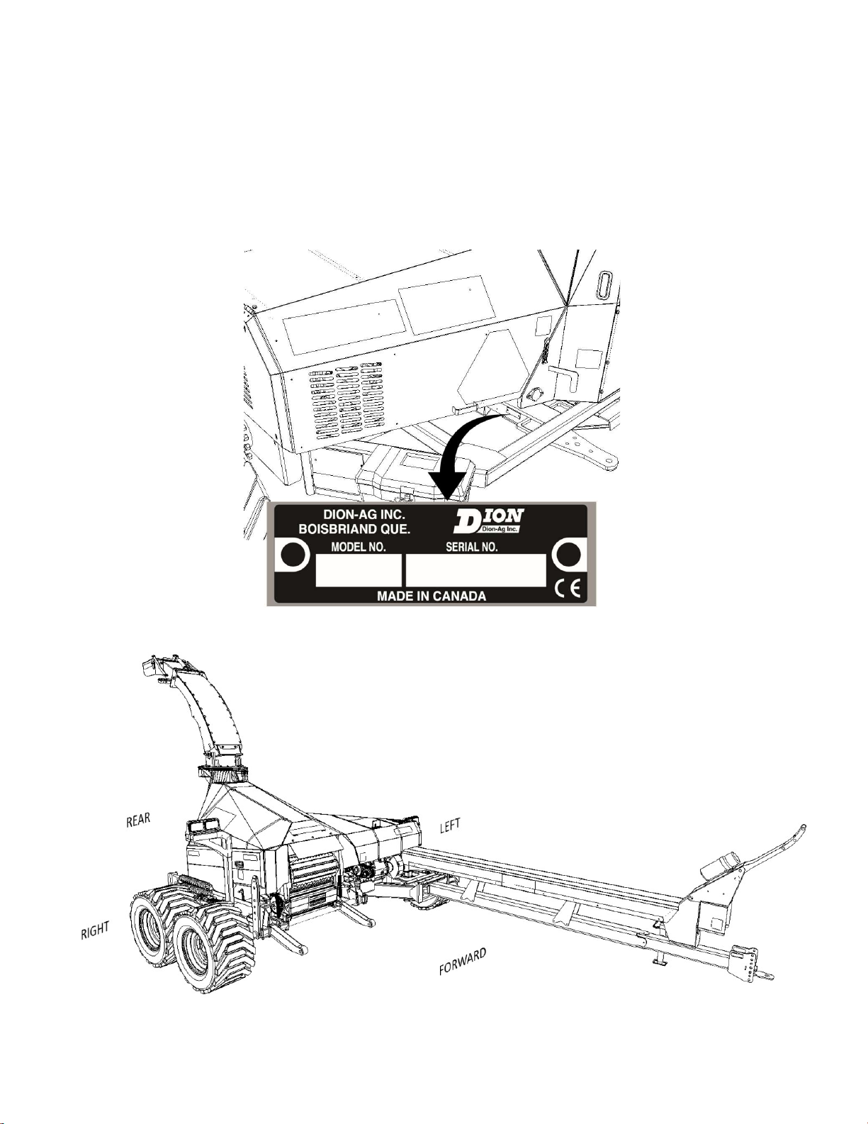
SERIAL NUMBER LOCATION
For your convenience, write down the full model and serial number of your machine in this manual, as shown on the
name plate illustrated below. Always mention both the model and the serial number when ordering parts or regarding
any other correspondence with your machine.
Write down your number here:
MODEL NO.: ___________________________ SERIAL NUMBER: ___________________________
Figure 1 Serial number
Figure 2 Machine orientation

SAFETY RULES
A WORD TO THE OPERATOR
It is the responsibility of the OWNER to read and fully understand the safety section in this manual before operating your
tractor. You must follow these safety instructions that will assist you step by step throughout your workday.
After reading this section, you will note that illustrations have been used to highlight certain situations. Each illustration
is numbered and the same number appears in the text in parenthesis.
Remember that YOU are the key to safety. Good safety practices not only protect you, but also the people around you.
Study the features in this manual and make them a working part of your safety program.
Think SAFETY! Work SAFELY!
CODES AND SYMBOLS
The symbol below calls attention to instructions concerning your personal safety. It is found throughout the manual as
well as on the machine to point out specific hazards and ways to avoid these hazards. Always follow the instructions to
minimize the risk of personal injury or death.
SAFETY SYMBOL
DANGER, WARNING AND CAUTION
Whenever you see the words and symbols shown below or used in this manual and on decals, you MUST take note of
their instructions as they relate to personal safety.
DANGER: This symbol together with the word DANGER indicates an imminently hazardous situation that, if not
avoided, will result in DEATH OR VERY SERIOUS INJURY.
WARNING: This symbol together with the word WARNING indicates a potentially hazardous situation that, if not
avoided, could result in DEATH OR SERIOUS INJURY.
CAUTION: This symbol together with the word CAUTION is used to indicate a potentially hazardous situation
that, if not avoided, may result in MINOR INJURY.
IMPORTANT: The word IMPORTANT is used to identify special instructions or procedure which, if not strictly observed,
could result in damage to, or destruction of the machine, process or its surroundings.
NOTE: The word NOTE is used to indicate points of particular interest for a more efficient and convenient service and
operation of the machine.
FOLLOW A SAFETY PROGRAM
For safe operation of a Forage Harvester, you must be a qualified and authorized operator. To be qualified, you must read
and understand the written instructions supplied in this Operator’s Manual, have training, and know the safety rules and
regulations for the job.
Some regulations specify that no one under the age of 16 years, for example, may operate power machinery. This includes
tractors. It is your responsibility to know what these regulations are, and obey them, in the operating area or situation.
These will include, but are not limited to, the following instructions for proper operation.

SAFETY RULES
13
GENERAL SAFETY RULES
CAUTION: In some of the illustrations used in this Operator’s Manual, panels or guards may have been removed
for clarity. Never operate the machine without these components in place.
CAUTION: An operator should not be under the influence of alcohol or drugs which can alter alertness or
coordination. An operator on prescription or “over the counter” drugs needs medical advice on whether or not
he or she can operate machines.
CAUTION: DO NOT remove or obscure Danger, Warning, Caution or Instruction Decals that are not legible or
are missing. Replacement decals are available from your Dealer in the event of loss or damage. The actual
location of these Safety Decals is illustrated on page SAFEY SIGN LOCATION, See SAFEY SIGN LOCATION.
Wear appropriate clothing, safety boots or shoes.
Keep children away from the machine at all time.
Do not operate the machine when visibility is bad, or during night, in poor lighting.
Do not allow anyone to ride on the machine at any time.
The tractor ignition key must be removed every time the operator leaves the tractor.
Keep hands and body out of hitch area when attaching towing vehicle.
Carefully read the safety decals on the machine. If any are damaged, replace them immediately.
PTO OPERATION
Before starting the tractor engine, make sure that the PTO driveline locking device is properly engaged onto both
the tractor and equipment drive shafts. Secure the safety chain to the tractor frame.
Never proceed to start the machine before making sure all driveline, machine and tractor shields are properly
installed in place.
Never wear loose clothing and keep people, especially children away from the driveline.
The PTO driveline shields should turn freely, be well connected and be maintained in good condition.
Do not connect a tractor with a PTO speed of 1000 RPM on a machine equipped with a 540 RPM drive.
Do not connect a tractor with a PTO speed of 540 RPM on a machine equipped with a 1000 RPM drive.
Keep a good distance away from a rotating driveline (approximately the distance greater to your height).
Never step across any PTO driveline.
Never use the PTO driveline as a step.

SAFETY RULES
14
PREPARATION AND OPERATION
Before starting the tractor engine, make sure all guards, shields, and doors are in place and properly secured and
check the machine thoroughly for possible loose parts or bolts. Make any necessary adjustments.
Use a lift system with a minimum lifting capacity of 2500 lbs (1150 kg) to install a header on the forage harvester.
Refer to the header specifications.
Never operate a Forage Harvester without first having installed a header.
If a feeding or throwing mechanism should become jammed, never attempt to unblock it or remove any material
when the machine is in motion or while the tractor engine is running.
Make sure all rotating parts are stopped and the tractor engine is turned OFF before cleaning the machine throat.
Never stand underneath the forage harvester deflector or forage path when the machine is running. Keep the
discharge spout toward the forage box.
MANDATORY STOPPING PROCEDURE
No matter what type of machine is being used, it is extremely hazardous to perform any kind of maintenance work while
the machine is running. It could lead to serious injuries or even death. Before cleaning, adjusting or greasing the machine,
the following procedure should be followed to stop the Forage Harvester:
1. Place the transmission in neutral.
2. Disengage the PTO from the tractor.
3. Switch off the forage harvester control box.
4. Switch off the oil flow (distribution valve).
5. Switch off the tractor engine.
6. Apply the tractor's safety brake.
7. Wait until all rotating parts have completely stopped.
8. Disconnect the PTO input shaft from the tractor's PTO.
9. Block all wheels.
DANGER: Rotating driveline contact may cause serious injury or death.

SAFETY RULES
15
INSPECTION, MAINTENANCE AND ADJUSTMENTS
WARNING: Hydraulic fluid under pressure can penetrate the skin or eyes and cause serious personal injury,
blindness or death. Fluid leaks, under pressure, may not be visible. Use a piece of cardboard or wood to find
leaks. DO NOT use your bare hand. Wear gloves and safety goggles for eye protection.
CAUTION: Hydraulic lines and components can become very hot in operation and cause burns. Wear gloves and
safety goggles for eye protection.
Never proceed to start the machine before making sure all driveline, machine and tractor shields are well installed
and in place.
Never lubricate or clean any part while the machine or tractor engine is running.
Never attempt to check or adjust chains while the machine is running.
Disengage the PTO and shut off engine before leaving the operator’s seat for refueling, lubricating or adjusting
the machine.
When performing a metal detection test, stop the PTO, wait until all moving parts are stopped, then disconnect
the PTO from the tractor.
Securely block the wheels from moving before working on or under the machine.
If necessary, to work under or close to moving parts that may crush or hit you, block their movement to make the
working environment safe.
Make sure that all wheel bolts are properly torqued.
When knives are being readjusted, a piece of wood should be used to immobilize the cutting head.
Always pick-up tools after performing any adjustment.
TRANSPORT AND STORAGE
Maximum traveling speed of a forage harvester should not exceed 32 km/h (20 mph).
Never pull a loaded wagon behind the harvester on the road.
Always use a draw pin of sufficient capacity, with a safety clip, to connect the harvester to the tractor and the
trailer to the harvester, for every trip on the road or in the field.
Attach a safety chain of at least 20,000 lbs (9071 Kg) capacity for transportation.
Always deactivate the hydraulic circuit of the harvester and turn off the control box before traveling on public
roads.
Ensure the spout is in lock position before traveling on the road.
When driving on a public road, or on hilly land, make sure the ‘Hitch Disconnect’ red safety cap is covering the
switch and install the locking pin in the stop pawl of the quick-disconnect hitch to prevent unlocking. This locking
pin should also be used for the manual quick-disconnect hitch.
Never disconnect a trailer on hilly land.
Make sure to meet local regulations for excessive width on public roads.
When storing or parking the harvester, always lower the header down to the ground.
SAFETY RULES
16
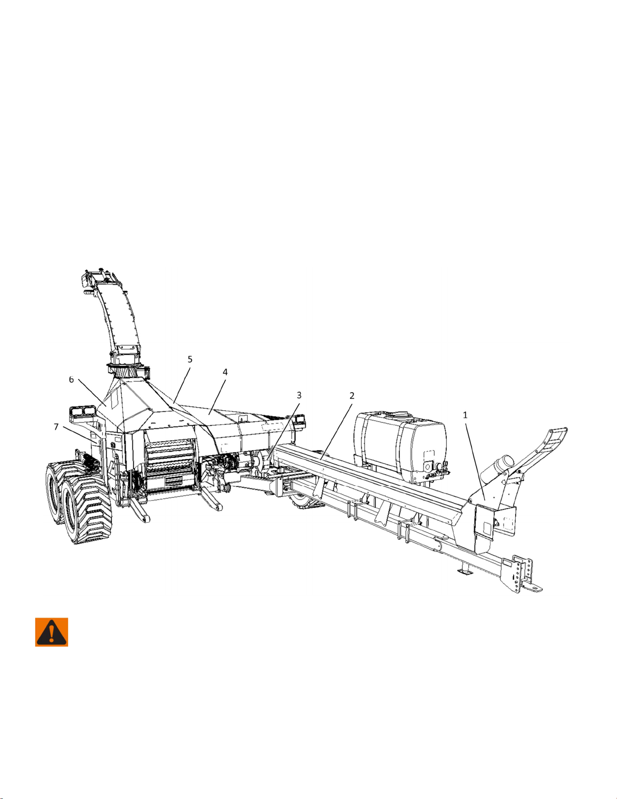
GUARDS AND SHIELDS
The Forage Harvester is equipped with guards and shields wherever accidents can occur. These guards and shields do not
affect the performance of the machine. Refer to Figure 3 to identify these guards and their location to make sure they
remain in place for a safe operation.
1. PTO shaft, cables and hose shield.
2. Transmission shaft guard.
3. Feed roll transmission pulley guard.
4. Main guard covering the power transmission components.
5. Left « Butterfly guard » covering the processing element drive.
6. Right « Butterfly guard » covering the processing and sharpening elements.
7. Side guard covering the feed rolls and processor roll drive elements.
Figure 3 Location of the main guards
WARNING: All factory installed guards and shields should be in place and maintained in good condition.

SAFETY RULES
17
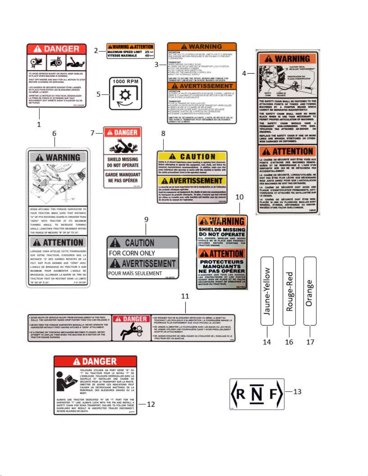
SAFEY SIGN LOCATION
Several decals located around the hazard areas indicate the potential dangers.
IMPORTANT: Decals must be kept clean to allow for visibility at all times.
Figure 4 Safety Decals
Figure 5 Safety Decals

SAFETY RULES
18
Figure 6 Safety Decals
Figure 7 Safety Decals
SAFETY RULES
19
Figure 8 Safety Decals
SAFETY RULES
20
Figure 9 Safety Decals
Table of contents
Other Dion-Ag Farm Equipment manuals


