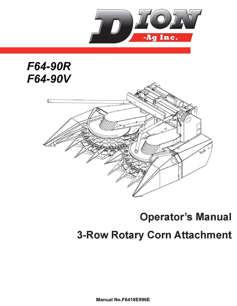
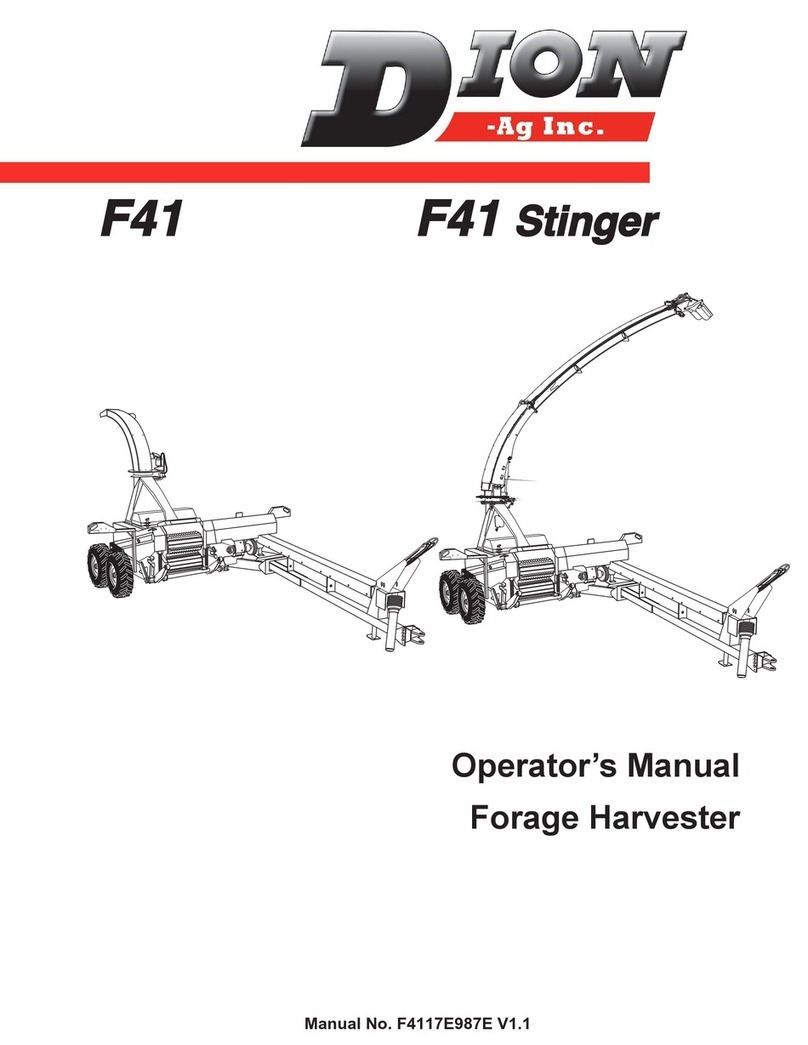
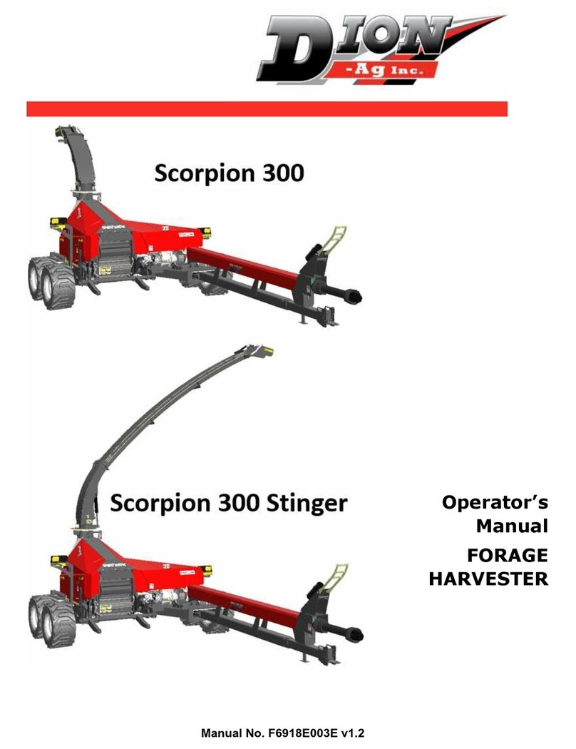
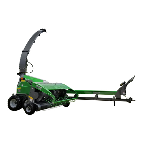
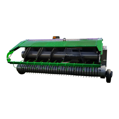
Dion-Ag Scorpion 300 Manual

1
Setup / PDI Guide
Manual no. F6920T020
v1.0
Scorpion 300/2430
Scorpion 350 Stinger

1
Foreword
We thank you for your confidence towards DION-Ag Inc. agricultural equipment. We have prepared this setup
guide with care & attention and have designed it as an essential tool that will allow you to prepare the machine
for delivery adequately and safely.
Carefully read this guide in order to familiarize yourself with the adjustment procedures and operation, before
delivering this machine. Keep in mind, this machine has been designed and tested to perform in most conditions.
However, its performance is tightly linked to the maintenance it receives.
This guide has been prepared with the latest available information at the time of publishing. The company reserves
the right to make any changes without prior notice.
Safety
The Safety section of your Operator’s manual is intended to point out some of the basic safety situations which
may be encountered during normal operation and maintenance of your Forage Harvester, and to suggest possible
ways of dealing with those situations.
This section is NOT a replacement for other safety practices featured in other sections of this guide.
The safety of the operator is one of the main concerns in designing and developing a new Forage Harvester.
Designers build in as many safety features as possible. However, every year accidents may occur which could have
been avoided by a few seconds thought and a more careful approach to handling farm machinery and implements.
Read and implement the safety instructions detailed within and share them with other operators.
Work safely. Always block the harvester wheels and turn off the tractor before working on the harvester.

2
Upon Reception
Inspect for damage, transportation problems
Parts that have moved
Movement of machines during transport
Loose straps or fasteners
Damaged by transport or fasteners
Contact or friction
Loose parts on the machine
Validate parts received against the packing slip
Headers (Corn and/or hay)
Drive kit for respective header
Validate the model of each unit
Serial number
Cutterhead, transmission, LOC range, etc.
Processor, PTO, Drawbar size, etc.
Take note and notify us if there is a problem
Any breakage, damage and missing parts must be reported to DION-Ag within 5 days
The delivery waybill must be signed and noted to identify any damage upon reception. Failure to do
so will void the possibilities of a claim.
Contact the service department [email protected] 450-437-3449

3
Handling Instructions
Use a forklift with a capacity of at
least 8500 lbs. and forks at least
42” long.
There are 2 slots on the harvester
frame for the forks. One
perpendicular to the axle and one
at a 45° angle.
Approach the harvester
perpendicular to the frame and
axle mount.
Advance the forklift through the
2 fork slots until the forks are
sufficiently under the pick up
point.
Fork pick up point under
the harvester frame.

4
WARNING: Approaching the
harvester without minding
the forks may result in severe
damage to the kernel processor.
Assistance is required when
setting up to lift the harvester.
Have a guide present to ensure
no contact is made between the
forks and the processor
assembly.
NEVER place the harvester
directly on the ground.
Ensure the harvester is properly
supported on blocks with a
minimum height of 6” (15cm) at
3 points as described.
1 point under the left axle.
1 point under the right header
attachment location.
1 point at the tongue, supported
by a block of wood OR the jack
stand which the harvester is
equipped with.
Kernel processor
assembly.
Fork pick up point under
the harvester frame.

5
Axle and Wheel Installation
Check all parts have been delivered.
Wheels, axles, axle mounting bolts.
Delivery includes 2 left wheels and 2
right wheels.
Install the wheels on the axles.
Note: Only ‘TerraTrac’ are directional
tires!!
They must be installed in “trailed"
mode as shown.
Position the axles flat on wooden
blocks and remove the wheel bolts.
Place the wheels onto the axles
ensuring the air valves face upwards.
Use a tire lifting tool OR two people to
place the tire onto the axle.
Install the 6 bolts by hand.
Tighten the 6 bolts to 120lb-ft (163
N.m.). Wheel torque should be check
after the first hour and every 20h for
the first 60h.
Repeat for all wheels.
Air valve facing upwards
Front of harvester

6
Axle Mounting (Right Side)
Remove the nuts and lock
washers on the right axle.
Install the axle extension and the
light pole (right side).
Install the 8 lock washers and
tighten all 8 nuts.
Lift the harvester with a forklift.
Advance the harvester to the
right side tandem and slide the
tube into the hole of the
harvester.
The axle should slide in easier
when the harvester is lifted to
approximately 18” between the
ground and the frame.
The longer portion of the axle
should be towards the rear of the
harvester.
Use the lock pin and cotter pin in
the toolbox to fix the axle to 1 of
the 3 desired position (3 holes in
the long tube).
Typically, the axle should be
installed with no holes exposed
(axle tube assembly as close to
the harvester as possible).
Approach the harvester perpendicular.
Ensure the forks do not make contact
with the kernel processor.
Longer portion of the axle towards the rear.
The tube must be
installed so that
the metal plates
face upwards.

7
Axle Mounting (Left Side)
After installing the tandems on the
right side, approach the harvester
perpendicularly.
Place the left side of the harvester
safely on blocks.
Remove the nuts and lock washers
from the axle assembly.
Lift the tandem wheel assembly.
Ensure the longer portion of the
assembly faces the front of the
harvester.
Mate the axle assembly to the hub
on the harvester and install the
lock washers and nuts by hand.
Tighten the 8 nuts ensuring the
carriage bolts remain properly
seated.
Lift the harvester and remove
blocks.
Longer portion of the axle towards the front.

8
Light Installation (left side)
Locate the lights in a carton
underneath the butterfly guards
of the harvester.
The cable on the harvester is
secured in place for transport.
Open the main guard and cut the
cable ties.
Remove and keep the fasteners
for the light assembly.
Pull the cable through the
opening.
Use the cable ties in the toolbox
to affix the cable to the arm.
Place the connector as shown
and loop any excess cable.
Insert the light assembly through
the opening.
Fasten the assembly with the
hardware you removed earlier.
The light assembly can be
installed to accommodate 2
widths. Install according to the
desired width.
Cut cable ties.
Pull the cable out.
Fasten light bar.

9
Light Installation (right side)
Install the correct light assembly according to the header being used.
If the header is one of the following, no extension
is required:
Hay pick up F46 –2.13m (84”)
3 Row corn head F64 –2.3m (90”)
If the header is one of the following, an extension
must be used:
Hay pick up F71 –2.74m (108”)
4 Row corn head F61 –3m (120”)
Removing the extension arm to make the short
base:
Unscrew the 4 bolts securing the light to the
extension.
Install the light onto the main support using the
same hardware.
Ensure the wires are not pinched during the
installation.
Affix the cable to the assembly using cable ties.
Without extension.
With extension.
Install the light onto
the main support.
Extension removed.
Remove the light.

10
Attach the extension to the pole with the
provided bolts.
The cable is looped within the frame section for
transport. Cut it free.
Pass the wire of the harvester through the light
pole and guide it through the oblong hole.
Prior to fastening the cable, ensure to leave
sufficient slack in the cable for when the light is
the raised position.
Loop excess wire and fasten with cable ties and
ensure wires do net get pinched.
Use this locking pin when the extension arm is in
the up or down position.
Ensure the cable is not pinched when the
extension arm is lowered to the down position.
Extension arm in the ‘down’ position.
Extension arm in the ‘up’ position.
Locking pin (down)
Locking pin (up)

11
Hay head
To remove the head from the
transport skid, remove and
discard all fixing hardware and all
yellow securement wire.
Lift the assembly using the single
point lift hook.
Rotary corn head
Do NOT lift the assembly using the handling
arm.
This assembly is heavy. Use a forklift equipped
with 8’ forks.
Prepare wood blocks to ensure the header is not
placed directly onto the ground.
NEVER stand under or around an unsecured
machine!
Attach the chain securely to the handling arm
and the forks of the forklift.
Provide enough slack in the chain so that when
you reverse with the forklift, the head can be
lowered slowly to the ground.
Before reversing, start with the chain at ~45°
angle as shown. Once the head pivots, lower
the forks slowly as you continue to reverse.
Once flat on the ground, unbolt and remove the
metal skid and the handling arm.
Use the single point lift to maneuver the head
once it is safely on the ground, on wood blocks.
Single point lift hook.
Handling arm.
Single point lift.

12
Toolbox Content
Static Inspection
Fluid leak
Gearbox & transmission oil level
Pinched hydraulic line or electrical cable
Gap of approximately 1/4” between closed guards
Main guard
Butterfly guards
Loose bolts or loose parts
Damaged or faded safety decals
Shields and doors close smoothly
Main guard
Butterfly guards
Guillotine door
~1/4” Gaps
between main
guard and the
butterfly guard.

13
Parts Verification
Wheels and axles
Lights (left & right)
PTO shaft
Safety chain
Operator’s manual and registration (inside black
plastic can on all DION machines)
Control box and mounts (Scorpion 300/240)
Options Verification
Stinger spout kit
Camera(s) & monitor
LED lights
Quick attach kit
Inoculant applicator kit
Isobus & joystick (Scorpion 350)
Processor roll clamp and rubber mat
Rubber mat (1x) (# 31775)
Strap (1x) (# 31506+Y)
Flat washer (2x) (# RP12Z)
Elastic nut (2x) (# EP12Z)
Manual / Delivery and
Warranty Registration
Inoculant system is standard with 1x 50GAL tank.
Optional with an additional 50GAL tank.

14
Transport Plates
Spout
DANGER: Removal of this spout bracket must be done prior to operating any of the
hydraulic systems. Failure to remove this bracket before operating the hydraulics could
result in injury or death.
In certain transport scenarios, the spout must be lowered in order to fit transport enclosures. This is achieved by
utilizing a temporary support bracket.
The spout is heavy. Support the
spout safely with a lifting strap and
use an overhead chain block or
another lifting implement to lift.
Be mindful not to pinch hydraulic
lines or wiring. Do not use a chain
to lift the spout.
Remove and retain the 4 bolts and
nuts (2 each side).
The spout may have shifted during
transport. The spout may need to
be jostled in order to remove the
bolts.
Discard the yellow curved support
bracket.
Slowly lift the spout with the lifting
implement. If it does not pivot,
loosen the remaining 2 bolts more.
Do not remove them.
While lifting, the spout pivot
should rotate and fall into place as
shown in the photo.
Once the pivot is fully seated, the
bolts and nuts can be reinstalled.
Tighten all 4 bolts and nuts (2 on
each side).
This bolt will need to be loosened
on both sides of the spout in order
for it to pivot. Do not remove it.
Remove and retain the
4 bolts and nuts. 2 from
each yellow bracket.

15
Tongue
The drawbar lock plate
(yellow) is meant to act as a
lock during transport.
Remove the hardware
affixing it to the frame and
discard the hardware and
the locking plate.
Setup Instructions
Refer to the operator's manual for additional preparation information.
Tractor connections
The hydraulic lines are heavy. Do not route electrical lines
through the same rung as the hydraulic lines.
Route the hydraulic lines, through the handle, between the
1st and 2nd rung.
Route the hydraulic lines, through the handle, between the
2nd and 3rd rung.
Tractor setup (see operator’s manual)
Scorpion 300/2430:
Connect the “P” line to an SCV with continuous flow set at 10l/min (2.5gpm)
Connect the “T” line to a ‘Motor Return’port on the tractor. Connecting to an SCV might trap
pressure or increase return line pressure and cause hydraulic malfunction.
********************************
Scorpion 350:
Always ensure the tractor is OFF before making connections
Ensure correct couplers are equipped
To prevent damage to the hydraulic system
Connections should be made in order of: D, T, LS, P
Disconnect in this order: P, LS, T, D
Rungs
1st
2nd
3rd

16
Installation and alignment of draw bar (#4) and PTO (#2) (See operator’s manual)
Install drive kits onto headers
Install the F64/F61 Corn head drive kit
An installation guide is provided with the Corn Head Drive Kit

17
Adjust feed roll throat guards when mated to the harvester (#14)
Test the corn header on the harvester to ensure drive and
suspension functionality
Clean & polish headers
For a Scorpion 300 and 2430 models no drive kit is required to install on the hay pick-up.
For the Scorpion 350, a special drive kit is required for the hay pick up. An installation guide is provided.
Test ALL headers on the harvester to ensure drive and suspension functionality
Hay / corn crop conversion on the harvester depending on crop to harvest (See operator’s manual)

18
Pre-delivery Inspection
Ensure you have the latest software version (update from https://www.dion-ag.com/tech-en/)
Connect with the ‘Windtools’ service software (see Windtools manual)
In the live data tab, plot all speed sensors and check for abnormal noise levels with the machine in operation
Data #2011 and #2012 for Scorpion 300 and 2340
Data #2004, #2026, #2030, #2050, #2060 for Scorpion 350

19
Adjust sensors gap and alignment, if necessary, to obtain very smooth lines
Check metal detector signal noise at zero speed
Data #2010 for Scorpion 300 and 2430
Data #2040 for Scorpion 350
Signal should be <100mV. If higher, verify ground connection/bad ground OR moisture between connector
(controllers, valves, etc.)
Plot threshold, signal and mean voltage
Data #2006, #2007 and #2010 for Scorpion 300 and 2430
Data #2040, #2042 and #2041 for Scorpion 350
Other manuals for Scorpion 300
1
This manual suits for next models
2
Table of contents
Other Dion-Ag Farm Equipment manuals
Popular Farm Equipment manuals by other brands
Landoll
Landoll Brillion SL10 Operator's manual

SCHMOTZER
SCHMOTZER Venterra 2K KPP-LSC Translation of the original operating instructions
HE-VA
HE-VA Combi-Disc Series operating instructions

MASSEY FERGUSON
MASSEY FERGUSON 2140 - Workshop service manual
CAMPAGNOLA
CAMPAGNOLA ELEKTRA Use and maintenance manual

Arrowquip
Arrowquip EASY FLOW product manual
