Midwest Mid-Tech TASC 6200 User manual

Midwest Technologies Illinois, LLC
Springfield, IL 62703
MID-TECH
Midwest Technologies Illinois, LLC
®
TASC 6200/6500
TOTAL APPLICATION
SPREADER CONTROL SYSTEM
OPERATING MANUAL
PN - 999-1511
Revision# -96162

INDEX OF CHANGES
DATE DATE CODE DESCRIPTION
01/10/94 94010 Software Ver 1.5 update, Entire Manual
05/20/94 94139 Software Ver 2.2 update, Entire Manual
04/11/95 95090 Minor corrections, reformate entire manual
07/14/95 95195 Software Ver 2.5 update, Entire Manual
08/21/95 95233 Cal. Constants 6-12, Fld cal Gran. Biins
06/10/96 96162 Minor corrections

999-1511
TASC 6200/6500
M-T 96162
3
INDEX OF CHANGES ....................................................................................................................................... 2
TABLE OF CONTENTS ..................................................................................................................................... 3
1.0 INTRODUCING TASC FOR THE NEW GENERATION SPREADERS .......................................................... 5
TASC 6500 SYSTEM DIAGRAM ................................................................................................................. 6
TASC 6200 SYSTEM DIAGRAM ................................................................................................................. 7
2.0 SWITCHES AND CONTROLS .................................................................................................................... 8
2.1 POWER SWITCH ................................................................................................................................. 8
2.2 MODE SELECTOR " OPERATE/SET-UP " SWITCH ............................................................................ 8
2.3 THE INC/DEC SWITCH ........................................................................................................................ 8
2.4 THE DISPLAY SELECTOR SWITCH .................................................................................................... 8
DISPLAY SELECTOR SWITCH POSITION TABLE ............................................................................... 9
2.5 BOOM SECTION "ON/OFF" INDICATORS ......................................................................................... 10
2.6 FLOW CONTROL CHANNELS, RATE SELECTION SWITCHES ........................................................ 10
2.7 CHEMICAL APPLICATOR CHANNELS, RATE SELECTION SWITCHES ........................................... 10
2.8 BOOM CONTROL SWITCHES ........................................................................................................... 11
2.9 GROUND SPEED OVERRIDE SWITCH ............................................................................................. 11
2.10 STATUS SWITCH ............................................................................................................................. 12
2.11 FUSES AND POWER CONNECTIONS ............................................................................................ 12
3.0 OPERATION ............................................................................................................................................. 13
3.1 NORMAL START UP AND OPERATION ............................................................................................ 13
3.1.1 CALIBRATION NUMBERS AND CONSTANTS .......................................................................... 13
3.1.2 APPLICATION RATES .............................................................................................................. 13
3.1.3 ACCUMULATED AREA ............................................................................................................. 13
3.1.4 ACCUMULATED AMOUNTS ..................................................................................................... 13
3.1.5 OPERATE ................................................................................................................................. 13
3.1.6 CHECK THE VEHICLE .............................................................................................................. 14
3.1.7 START APPLYING .................................................................................................................... 14
3.1.8 STOP APPLYING ...................................................................................................................... 14
3.2 GROUND SPEED OVERRIDE (GSO) ................................................................................................. 14
3.3 CHANGING ACTIVE BOOM SECTIONS ............................................................................................ 14
3.4 CHANGING APPLICATION CHANNELS ............................................................................................ 15
3.5 CHANGING APPLICATION RATES ON THE GO ............................................................................... 15
3.5.1 ALTERNATE APPLICATION RATES FOR EACH CHANNEL ..................................................... 15
3.5.2 CHANGING THE PERCENT RATE ON THE CARRIER CHANNEL ONLY ................................. 15
3.5.3 CHANGING THE PERCENT RATE OF CHANNELS 1,2,3 AND L SIMULTANEOUSLY .............. 16
3.5.4 CHANGING THE PERCENT RATE OF ALL CHANNELS SIMULTANEOUSLY ........................... 16
3.6 MANUAL OVERRIDE OF FLOW CONTROLS..................................................................................... 16
3.6.1 OVERRIDE CHANNEL C CONTROL ......................................................................................... 16
3.6.2 OVERRIDE CHANNEL L CONTROL ......................................................................................... 17
4.0 FLUSHING AND CLEANING ..................................................................................................................... 18
5.0 MAINTENANCE ........................................................................................................................................ 19
5.1 TASC CONTROL CONSOLE ............................................................................................................... 19
5.2 GROUND SPEED SENSOR ............................................................................................................... 19
5.2.1 WHEEL SENSOR: .................................................................................................................... 19
5.2.2 RADAR SENSOR: ..................................................................................................................... 19
5.3 FLOW METER.................................................................................................................................... 19
5.4 HYDRAULIC FLOW CONTROL VALVES ............................................................................................ 20
5.5 LIQUID FLOW CONTROL VALVES ..................................................................................................... 20
5.6 ROTATIONAL SENSORS ................................................................................................................... 20
5.7 MID-TECH PERISTALTIC LIQUID INJECTION PUMPS ..................................................................... 20
5.7.1 DAILY ........................................................................................................................................ 20
5.7.2 WEEKLY ................................................................................................................................... 20
5.7.3 SEASONAL .............................................................................................................................. 21
5.7.4 PERIODIC ................................................................................................................................ 21
TABLE OF CONTENTS

999-1511
TASC 6200/6500
M-T 96162
4
5.8 OTHER INJECTION PUMPS .............................................................................................................. 21
5.8.1 SEASONAL: ............................................................................................................................. 21
5.8.2 PERIODIC: ............................................................................................................................... 21
5.9 WIRING HARNESS ............................................................................................................................ 22
6.0 CALIBRATION AND SET UP ..................................................................................................................... 23
6.1 SETTING APPLICATION RATES ........................................................................................................ 23
6.1.1 SETTING CONVEYOR APPLICATION RATE ............................................................................. 23
6.1.2 SETTING CONVEYOR PRODUCT DENSITY ............................................................................ 23
6.1.3 SETTING ALL OTHER APPLICATION RATES ........................................................................... 24
6.1.4 SETTING PRODUCT DENSITY, CHANNELS 1, 2 and/or 3 ........................................................ 24
6.2 SETTING THE % RATE CHANGE ....................................................................................................... 25
6.3 SETTING BOOM WIDTHS .................................................................................................................. 25
6.4 SETTING THE SPLIT DRIVE OPTION ............................................................................................... 26
6.5 SETTING CHEMICAL APPLICATOR CHANNELS TO PERISTALTIC OR NON-PERISTALTIC ............ 27
6.6 SET THE GROUND SPEED OVERRIDE SPEED (GSO) ..................................................................... 27
6.7 DISTANCE CALIBRATION ................................................................................................................... 28
6.7.1 INITIAL CALIBRATION SETTINGS ............................................................................................ 28
6.7.2 DISTANCE CALIBRATION PROCEDURE .................................................................................. 28
6.8 CONVEYOR CALIBRATION, CHANNEL C .......................................................................................... 29
6.9 CALIBRATING THE LIQUID CHANNEL, L ..........................................................................................31
6.10 CALIBRATING CHANNELS 1,2 AND 3 (not applicable to 6200) ........................................................ 32
6.10.1 CALIBRATING MID-TECH® INJECTION PUMPS .................................................................... 32
6.10.2 CALIBRATING GRANULAR BIN APPLICATORS ..................................................................... 34
6.11 SETTING THE HOLD OR CLOSE RESPONSE OF CHANNEL C AND L CONTROL VALVES ........... 35
7.0 TROUBLE SHOOTING TASC ..................................................................................................................... 36
7.1 ERROR MESSAGE Err, INVALID SET-UP PROCEDURE .................................................................... 36
7.2 ERROR MESSAGE Err E, INVALID MEMORY .................................................................................... 36
7.3 ERROR MESSAGE Err 0, INVALID CONSTANT SET TO ZERO ........................................................ 37
7.4 ERROR MESSAGE Err-1, 2, 3, 4, & 5, INVALID OPERATION ............................................................ 37
7.4.1 ERROR MESSAGE Err-1 ........................................................................................................... 37
7.4.2 ERROR MESSAGE Err-2 ........................................................................................................... 38
7.4.3 ERROR MESSAGE Err-3 ........................................................................................................... 38
7.4.4 ERROR MESSAGE Err-4 ........................................................................................................... 39
7.4.5 ERROR MESSAGE Err-5 ........................................................................................................... 40
7.5 ERROR MESSAGE OFLO, NUMERIC OVERFLOW ........................................................................... 40
7.6 ERROR MESSAGE Err L, LOW VOLTAGE .......................................................................................... 40
7.7 ERROR MESSAGES Err C, n, hook (backward 7), INTERNAL DIAGNOSTICS ................................... 40
7.8 ERROR MESSAGE Err P, PRINT UNABLE ......................................................................................... 40
FLUID OUNCES CONVERSION TABLE .......................................................................................................... 41
USEFUL FORMULAS ...................................................................................................................................... 42
TASC 6200/6500 SYSTEM DIAGRAM ............................................................................................................. 43
WARRANTY .................................................................................................................................................... 45

999-1511
TASC 6200/6500
M-T 96162
5
1.0 INTRODUCING TASC FOR THE NEW GENERATION SPREADERS
The TASC 6500 is a five channel controller. Two channels are designed to operate positional control
valves while the other three channels are designed to operate either proportional control valves or DC
motors. This gives the MID-TECH TASC 6500 the flexibility to control almost any mobile applicator using a
single console.
All five channels control spread or spray rates in relation to ground speed and width. Each channel has two
programmable rates or can be changed by a percentage amount ON THE GO. The TASC 6500 is easy to
calibrate and operate and incorporates many self check features to help the operator keep his system
running in top condition.
The TASC 6200 is a simpler version of the TASC Spreader Control. TASC 6200 controls two channels
designed to operate positional control valves. Typically, this would be a conveyor and a wet boom.
The following schematics show a few MID-TECH TASC 6500 system possibilities.
TASC-6500
CHEMICAL APPLICATORS
123
ON
OFF
Alt.-
RATE
%Rate
DISPLAY SELECTOR
Speed
Area Width
Distance
Vol. Applied
Test
Speed
Fan RPM
Vol. Applied
Appl. Rate Appl. Rate
OFF SET- UP DEC
ON OPERATE INC
.
123456789
BOOMS
Scan
MID-TECH
¨
MIDWEST TECHNOLOGIES,
INC. RATE CONTROL CHANNELS
L & CHEMICALS CARRIER
Mph
LC
MIDWEST TECHNOLOGIES, INC.
TASC 6200/6500 SPREADER CONTROL

999-1511
TASC 6200/6500
M-T 96162
6
TASC 6500 ON LORAL AIR MAX WITH THE WET BOOM OPTION, ONE INJECTION PUMP AND TWO
GRANULAR COAPPLICATOR BINS ON THE CONVEYOR.
TASC 6500 SYSTEM DIAGRAM
BATTERY
+-
INJECTION
PUMP
100-0042
3
1
TASC 6500
114-0005
123FAN
BIN CLUTCHES
1
2
GRANULAR SWITCH BOX
105-0015
BOOM INTERFACE
CHANNEL C
CHANNEL L
FAN SENSOR
LC
DISCONNECT POINT IN
AG-CHEM AIR CYL BOX,
OR FRONT OF AIR-MAX
BED
602-0014
404-0049
602-0014
602-0014
602-0014
401-0009
401-0010
DISCONNECT POINT IN
AG-CHEM AIR CYL BOX,
OR FRONT OF AIR-MAX
BED
FAN 321 POWER
C
L
BOOM LC
404-0048
404-0055
404-0047
AIR CLUTCH
SWITCHED
+12 VDC
GROUND
LEFT
BOOM
RIGHT
BOOM
402-0030
402-0031
120-0101 FLOW METER
405-0056
WET BOOM
VALVE
CONVEYOR
RATE SENSR
CONVEYOR
VALVE
120-0021 SENSOR
INCLUDES CABLE
404-0003
HOPPER LEVEL/FLOW
MONITOR 105-0007
404-0003
404-0003
RED (WHITE)
+12 VDC
BLACK
GROUND
3 amp
ON
OFF
123 4
602-0014
602-0014
405-0066
DJ HOPPER LEVEL
SENSOR
A
A
A
A
NOTE: Shaded areas marked "A"
denote accessories which LORAL
procures from another supplier.
A
GROUND
SPEED
A
RADAR
401-0008
Or: KIT 500-0042,
Piston Pump Drive
REMOTE MASTER SWITCH
CONNECTION
A RED, +12 VDC
B BLACK, Open
BULLETIN # 999-1214
NOTE: 602-0014 required for
AG-CHEM chassis only. Not installed
on LORAL chassis.
NOTE: 602-0014 required for
AG-CHEM chassis only. Not
installed on LORAL chassis.
BIN SENSOR
120-0008
M
BIN MOTOR A
105-0104
Bin
Driver
M
BIN MOTOR A
105-0104
Bin
Driver
BIN SENSOR
120-0008

999-1511
TASC 6200/6500
M-T 96162
7
TASC 6200 SYSTEM ON A LORAL AIR MAX WITH WET BOOM OPTION
FAN SENSOR
A
BATTERY
+-
TASC 6200
114-0006
FAN
GRANULAR SWITCH BOX
105-0015
BOOM INTERFACE
CHANNEL C
CHANNEL L
LC
DISCONNECT POINT IN
AG-CHEM AIR CYL BOX
OR
FRONT OF AIR-MAX BED
404-0049
602-0014
401-0009
401-0010
DISCONNECT POINT IN
AG-CHEM AIR CYL BOX,
OR FRONT OF AIR-MAX
BED
FAN POWER
C
L
BOOM LC
404-0048
404-0055
404-0047
AIR CLUTCH
SWITCHED
+12 VDC
GROUND
LEFT
BOOM
RIGHT
BOOM
402-0031
120-0101 FLOW METER
405-0056
WET BOOM
VALVE
CONVEYOR
RATE SENSR
CONVEYOR
VALVE
A
NOTE: Shaded areas marked "A"
denote accessories which LORAL
procures from another supplier.
A
GROUND
SPEED
A
RADAR
REMOTE MASTER SWITCH
CONNECTION
BULLETIN # 999-1213
NOTE:
602-0014 USED ON THE
AG-CHEM CHASSIS ONLY, NOT
INSTALLED ON THE LORAL CHASSIS.
TASC 6200 SYSTEM DIAGRAM

TASC 6200/6500 999-1511
M-T 96162
8
TASC-6500
CHEMICAL APPLICATORS
123
ON
OFF
Alt.-
RATE
%Rate
DISPLAY SELECTOR
Speed
Area Width
Distance
Vol. Applied
Test
Speed
Fan RPM
Vol. Applied
Appl. Rate Appl. Rate
OFF SET- UP DEC
ON OPERATE INC
.
123456789
BOOMS
Scan
MID-TECH
¨
MIDWEST TECHNOLOGIES,
INC. RATE CONTROL CHANNELS
L & CHEMICALS CARRIER
Mph
LC
2.1 POWER SWITCH
The power switch controls power to the console. Turn power OFF when not in use. The console has a
nonvolatile memory so it will remember the constants and data previously entered, even if the vehicle
battery goes dead.
2.2 MODE SELECTOR " OPERATE/SET-UP " SWITCH
The mode selector switch selects between the operate mode and the set-up mode. This switch must be
in the operate position to begin applying. The set-up position is used for entering information to the
console. Anytime an incorrect switch setting is selected, an Err message will appear.
2.3 THE INC/DEC SWITCH
The INC/DEC switch is used to change values appearing in the display. This switch is also used to zero
accumulated data and to select special programming modes for the console.
2.4 THE DISPLAY SELECTOR SWITCH
The display selector switch is used to select and display the different console functions. It will display
different things depending on the mode selector switch setting. The following table will explain the
functions appearing for each display selector switch setting. Anytime an incorrect switch setting is
selected, an Err message will appear.
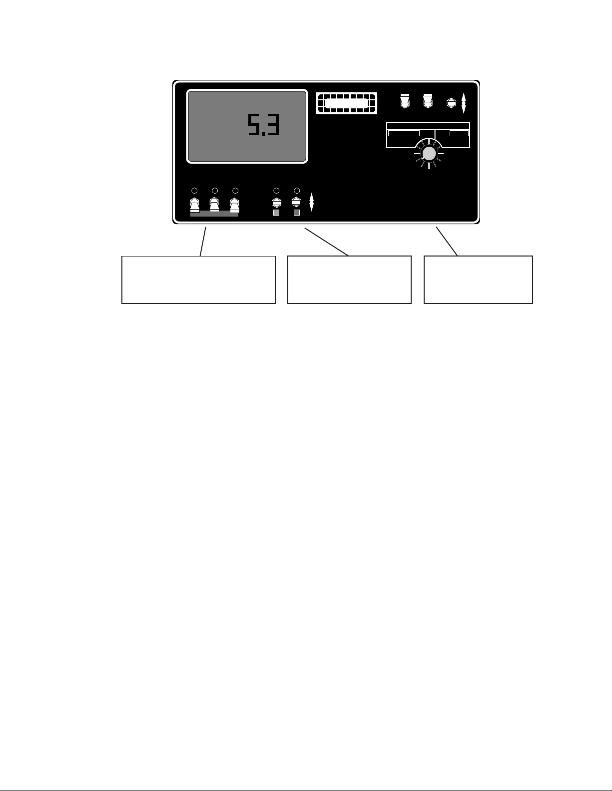
2.0 SWITCHES AND CONTROLS
The figure below shows the switches and displays on the TASC Spreader Control.
CHEMICAL APPLICATOR
RATE SWITCHES
CHANNEL L
AND C RATE
SWITCHES
DISPLAY
SELECTOR
SWITCH
INCREASE/DECREASE
SWITCH
MODE SELECTOR
SWITCH
POWER
SWITCH
DISPLAY
BOOM INDICATORS

95159
TASC 6200/6500
2-2
999-1511
DISPLAY SELECTOR FUNCTIONS IN THE
OPERATE MODE
DISPLAY SELECTOR FUNCTIONS IN THE
SET-UP MODE
Speed
Area
L & Chemicals
Vol. Appl.
L & Chemicals
Appl. Rate
L & Chemicals
% Rate
Carrier
Appl. Rate
Carrier
Vol. Applied
Width
Distance
Fan RPM
Test
Speed
Scan
The current vehicle speed in MPH The minimum speed for the GSO function. INC/DEC switch changes.**
Accumulated area in hundreths of an acre (999.99 Maximum)* Accumulated area in tenths of an acre (9999.9 Maximum) *
The amount of material actually discharged by channels 1,2,3 and L.
Units are not displayed. The display cycles through each position in
sequence unless a specific applicator is turned on. *
Calibration numbers for applicator positions 1,2,3 and L.
Err will
be displayed until an applicator position is selected. When channel is
non-peristaltic, density is displayed. When applicator is in split drive, all
booms must be on to view calibration number. INC/DEC changes.**
The target application rates (per acre) for channels 1,2,3. The dis-
play cycles through the active postions. INC/DEC changes by %. ***
The amount per acre to be applied by channels 1,2,3 and L. Each chan-
nel must be selected to ON and Alt-RATE in sequence. Two rates are
programable for each channel.
Err means incorrect switch setting. **
The percent of programmed rate at which all five channels are operating.
INC/DEC changes by a pre-set percentage. Alarm beeps and flashes in-
dicating abnormal operation. Switching display selector cancels. ***
The percent of change in application rate caused by each actuation of
the INC/DEC switch when in the operate mode. INC/DEC changes. **
The actual application rate by the conveyor while the vehicle is applying.
Shows the programmed rate while vehicle is at rest. INC/DEC changes
by a percentage. ***
The desired application rate for the Channel C. Two rates are program-
mable, the standard and the alternate rates. Channel switch (C) must
be on to set. INC/DEC changes. Product Density, C OFF**
The accumulated amount discharged by the conveyor. Reads pounds to
20,000 then shifts to hundredths of tons. *
The channel C/product calibration number. Calibrations should be ver-
ified for any change in density, flowability, gate setting, etc. INC/DEC
changes. **
The active boom width in feet. Depends on the actual boom sections
turned on.
Individual boom section programmed widths (inches). Display cycles
through all sections unless one is turned on. Boom section C is test
boom width. INC/DEC changes. **
Accumulated distance, miles after 5280. * The distance calibration number. **
If no applicators are selected the display indicates the pulses per rev of the
fan sensor. INC/DEC changes. **
The speed the console will use for stationary tests of the system. When
this switch sequence is selected, booms and applicators on, the system
will apply as if it were traveling at this speed. INC/DEC changes. **
The current test speed. INC/DEC changes. **
The display will scan operational functions, holding for about two
seconds at each position.
Err , invalid switch setting.
SWITCH
SETTING
Fan RPM.
NOTES: * Totals can be zeroed in this mode. ** Values are programmable in this mode.
*** Values changeable by a % increase or decrease.
DISPLAY SELECTOR SWITCH POSITION TABLE
TASC 6200/6500 999-1511
M-T 96162
10
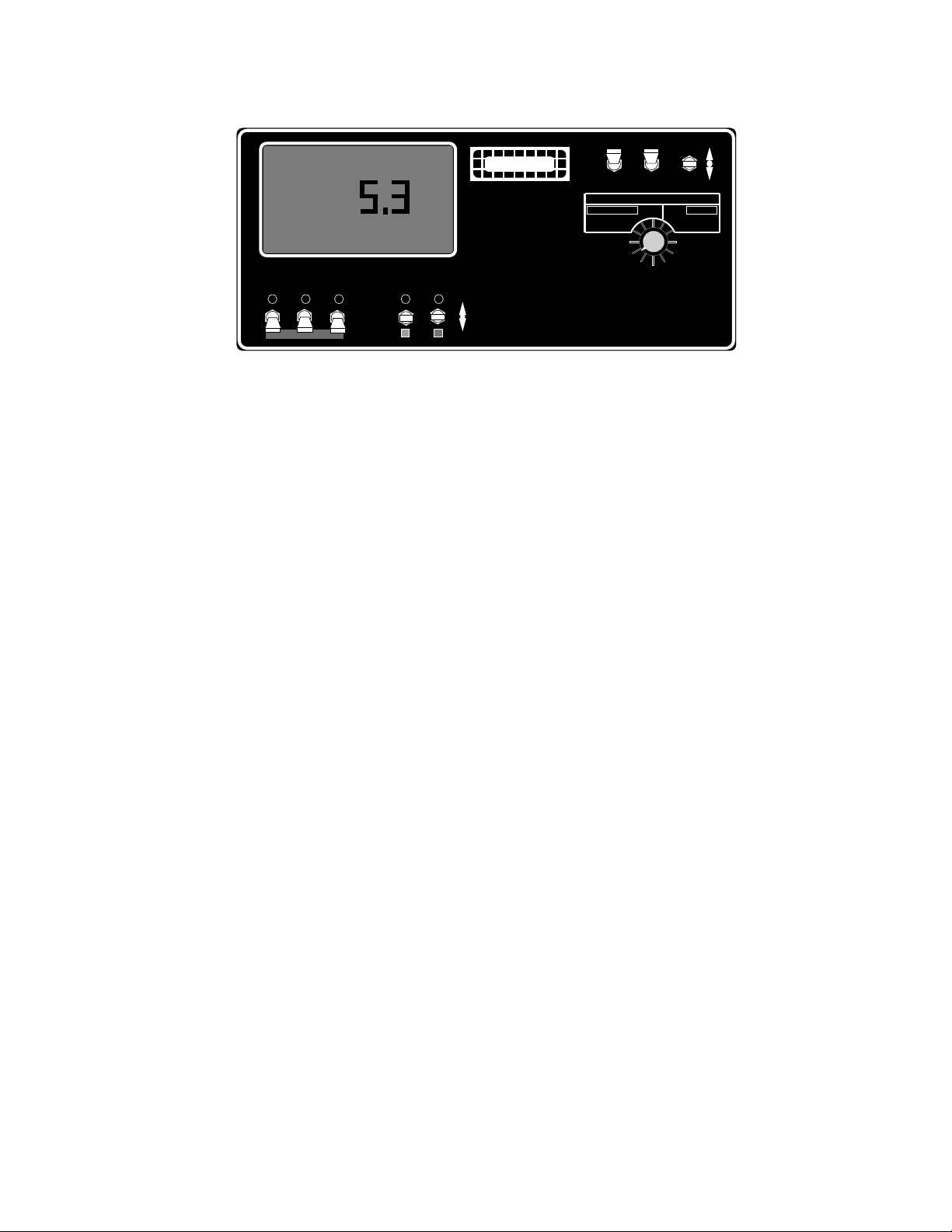
2.5 BOOM SECTION "ON/OFF" INDICATORS
The boom section on/off indicators show which boom sections have been selected by the operator.
There are a maximum of nine boom sections available. When a boom section is selected, its indicator
light will light.
2.6 FLOW CONTROL CHANNELS, RATE SELECTION SWITCHES
Two channels on the TASC are designated as flow control channels. Both are designed to operate
positional control valves. Channel C is set aside to control the spreader conveyor using a positional
hydraulic control valve.
Channel L would be used to control a liquid application using either a positional flow control valve or a
positional hydraulic control valve. This could be either a wet boom applicator or a liquid impregnation
applicator.
Both channels can be preset for a standard rate and an alternate rate. When the switch is turned on, its
indicator will light to show the applicator has been selected at its standard rate. When the alternate rate
is selected, the indicator light will flash to indicate a non-standard application.
2.7 CHEMICAL APPLICATOR CHANNELS, RATE SELECTION SWITCHES
(not applicable to 6200) Channels will not run without either Channel L or C ON.
Channels 1,2 and 3 are used to turn on and select the rate of up to three separate chemical applicators.
These three channels control using proportionally switched DC voltage. Typical installations will control
liquid injection pumps on a wet boom or granular coapplicators with a dry conveyor.
All three channels can be set for a standard rate and an alternate rate. When the switch is turned on, its
indicator will light to show the applicator has been selected at its standard rate. When the alternate rate
is selected, the indicator light will flash to indicate a non-standard application.
TASC-6500
CHEMICAL APPLICATORS
123
ON
OFF
Alt.-
RATE
%Rate
DISPLAY SELECTOR
Speed
Area Width
Distance
Vol. Applied
Test
Speed
Fan RPM
Vol. Applied
Appl. Rate Appl. Rate
OFF SET- UP DEC
ON OPERATE INC
.
123456789
BOOMS
Scan
MID-TECH
¨
MIDWEST TECHNOLOGIES,
INC. RATE CONTROL CHANNELS
L & CHEMICALS CARRIER
Mph
LC
BOOM SECTION
INDICATORS
CHEMICAL APPLICATOR
CHANNELS
FLOW CONTROL
CHANNELS

TASC 6200/6500 999-1511
M-T 96162
11
2.8 BOOM CONTROL SWITCHES
Externally mounted boom control switches are necessary for the proper operation of TASC. MIDWEST
TECHNOLOGIES can provide several optional configurations for these switches to meet differing needs.
The console must receive 12 VDC on the boom status line whenever a boom is turned ON.
A boom master switch is a good feature. It should be used to turn on or off all selected booms simulta-
neously.
2.9 GROUND SPEED OVERRIDE SWITCH
An optional ground speed override (GSO) switch can be used to temporarily operate the system using a
pre-selected minimum speed. GSO will bring the applicator on line quickly when starting from a dead
stop. GSO can also be used to maintain a minimum application rate when maneuvering the vehicle at
very low ground speeds. Finally, GSO can be used to empty the applicator from the cab while the vehicle
is stopped.
TASC operates normally, so long as the GSO switch is turned OFF. When the GSO switch is closed
(ON), and the actual ground speed is less then the minimum speed preset in the console, TASC auto-
matically selects the minimum speed value to control application rates. As soon as the switch is turned
OFF, or the actual ground speed increases above the minimum speed, TASC will control application rates
based on the actual ground speed.
If your GSO Switch is labeled "OFF / AUTO / GSO", the functions will be as follows. GSO will operate the
same as GSO ON above. AUTO will operate like GSO OFF above. The OFF position will operate the
same as turning the STATUS switch off. (See paragraph 2.10 below)
CAUTION: controlling application rates based on minimum speed is not as accurate as using the
actual ground speed. When GSO is being used and the actual ground speed is less than the mini-
mum speed, the console will sound a warning beep and flash a "Too Slow" message to warn the
operator of possible over application.
BOTHOFF OFF
MASTER
ON
WET BOOMS
ON
OFF
AUTO
MANUAL
Wet Boom
PUMP
Ground Speed
Override
BOOM
AUTO
¨
MID-TECH
MIDWEST TECHNOLOGIES, INC.
LEFT RIGHT
Mid-Tech 105-0015 Switch Box used on LOR*AL Air Max
TASC 6200/6500 999-1511
M-T 96162
12
2.10 STATUS SWITCH
An externally mounted status switch can be used to turn TASC on and off. So long as this switch is ON
(closed) TASC will operate normally. Whenever the switch is OFF (open), TASC will turn off the applica-
tor channels.
The intent of the status switch is to control TASC through the normal operation of the vehicle. The status
switch may sense the ON/OFF condition of the main applicator or it may sense an implement UP/DOWN
condition. Use of the status switch can lessen the operator work load.
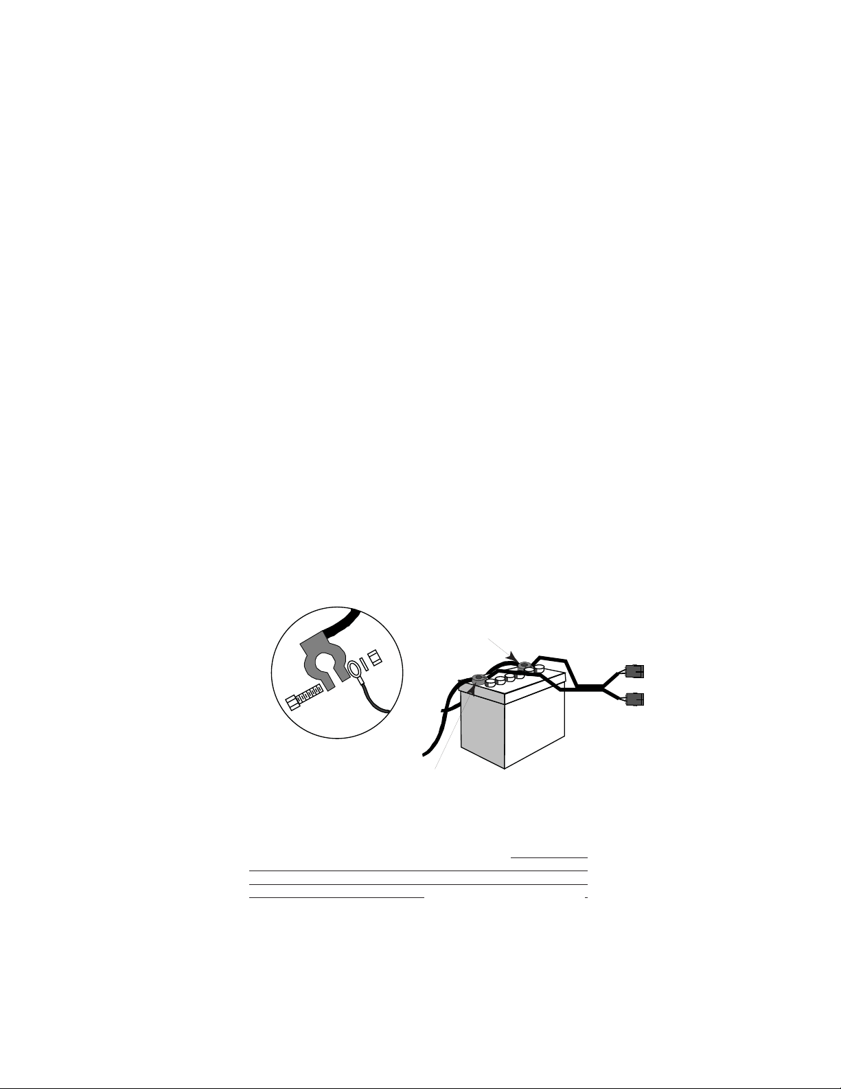
2.11 FUSES AND POWER CONNECTIONS
TASC uses the inherent capacitance of the vehicle battery to protect the electronics against voltage
spikes and electrical ground reference variations. For this reason:
IT IS EXTREMELY IMPORTANT THAT ALL CONNECTIONS BE MADE DIRECTLY TO THE VEHICLE
BATTERY. ON VEHICLES WITH MORE THAN ONE BATTERY, ALL CONNECTIONS SHOULD BE
MADE TO THE SAME BATTERY.
All fuses will be located near the battery connection. TASC components use automotive type, in line
fuses that are readily available from any auto parts store or most automotive repair facilities.
CONNECT ALL POWER LEADS DIRECTLY TO THE VEHICLE BATTERY
DO NOT SUBSTITUTE HIGHER AMPERAGE FUSES
12 Volts D.C.
Positive Terminal
Chassis Ground
Negative Terminal
AB
AB
Battery
Power
Cable
CAUTION!
THIS SYSTEM HAS BEEN DESIGNED TO GIVE OPTIMUM PER-
FORMANCE WHEN CONNECTED AS SHOWN. POWER CON-
NECTIONS OTHER THAN DIRECTLY TO THE VEHICLE BAT-
TERY AND/OR THE USAGE OF HIGHER AMPERAGE FUSES MAY
DAMAGE THE SYSTEM AND VOID THE WARRANTYVOID THE WARRANTY
VOID THE WARRANTYVOID THE WARRANTY
VOID THE WARRANTY.
TASC 6200/6500 999-1511
13 M-T 96162
3.0 OPERATION
TASC is designed to operate automatically. It will accurately apply chemicals, according to the
instructions it has received from the operator. Before applying chemicals, it is important to verify that the
proper registers are zeroed, and that the proper calibrations are entered in the console.
3.1 NORMAL START UP AND OPERATION
3.1.1 CALIBRATION NUMBERS AND CONSTANTS
With all boom sections OFF, check to see that the proper calibration numbers and constants are
entered in the console. Pay particular attention to the density factors for Channel C and any
granular bin channels. Refer to the calibration section of the manual for specific help.
3.1.2 APPLICATION RATES
With all boom sections OFF, and the MODE SELECTOR switch in the SET-UP position, review the
application rates for each control channel. Remember to look at the alternate rates also.
3.1.3 ACCUMULATED AREA
The area accumulators can be reset to zero by selecting AREA and holding the DEC switch until
the display resets to zero. There are two accumulators, one in the OPERATE mode and one in the
SET-UP mode. The accumulators are zeroed independently. Keep track of field area in the
OPERATE AREA and keep track of total area in the SET-UP AREA.
3.1.4 ACCUMULATED AMOUNTS
Check the accumulated total discharge from each channel by viewing CARRIER, VOL. APPLIED
or L & CHEMICALS, VOL. APPLIED, while in the OPERATE mode. Use the DEC switch to reset
to zero.
3.1.5 OPERATE
TASC 6500 is ready to start applying. Set the MODE SELECTOR switch to OPERATE. Turn ON
the proper control channels. Select an appropriate display function, SCAN for example.
TASC-6500
CHEMICAL APPLICATORS
123
ON
OFF
Alt.-
RATE
%Rate
DISPLAY SELECTOR
Speed
Area Width
Distance
Vol. Applied
Test
Speed
Fan RPM
Vol. Applied
Appl. Rate Appl. Rate
OFF SET- UP DEC
ON OPERATE INC
.
123456789
BOOMS
Scan
MID-TECH
¨
MIDWEST TECHNOLOGIES,
INC. RATE CONTROL CHANNELS
L & CHEMICALS CARRIER
Mph
LC

TASC 6200/6500 999-1511
14 M-T 96162
3.1.6 CHECK THE VEHICLE
Make sure the hydraulics (or liquid) pumps are engaged and operating normally.
3.1.7 START APPLYING
Drive the vehicle toward the application area and turn booms ON to start applying. TASC is
automatically controlling application of the selected channels. Area and amounts applied will begin
to accumulate. The console will display actual application rates.
3.1.8 STOP APPLYING
Reaching the end of the field, turn the booms OFF. The application will stop. After the vehicle has
turned, switch the booms back ON to control application.
3.2 GROUND SPEED OVERRIDE (GSO)
An optional ground speed override switch can be used to operate the sprayer using the GSO speed.
Ground speed override is used to bring the applicator channels on line quickly when starting from a dead
stop. Ground speed override will also ensure a minimum acceptable pattern when the vehicle is
maneuvering at very low ground speeds. GSO can also be used to flush the applicator channels from the
cab, with the vehicle stopped.
TASC operates normally when the GSO switch is in the OFF (open) condition. When the GSO switch is
ON (closed), and the actual ground speed is less than the GSO speed, TASC selects the GSO speed to
adjust the conveyor and chemical flow rates. When the actual ground speed increases above the preset
GSO speed, TASC will control flow rates using the actual ground speed. See the following table for a better
example of GSO operation.
CAUTION: Controlling application rates using GSO is not as accurate as using actual ground speed.
When GSO is active and the actual ground speed is less than the GSO speed, the console will sound
an alarm and the display will flash a Too Slow message to warn the operator about over application.
3.3 CHANGING ACTIVE BOOM SECTIONS
The active boom sections can be changed at any time by turning the boom switches ON or OFF. TASC
will automatically adjust application flow rates to account for the change in width. Area accumulators and
total applied accumulators also correct automatically for the change in width. When all boom sections are
turned OFF, application stops.
GSO GSO speed GROUND SPEED TASC CONTROL
OFF 5 MPH 6 MPH 6 MPH
OFF 5 MPH 4 MPH 4 MPH
ON 5 MPH 6 MPH 6 MPH
ON 5 MPH 4 MPH 5 MPH

TASC 6200/6500 999-1511
15 M-T 96162
3.4 CHANGING APPLICATION CHANNELS
TASC allows the operator to change the application channels ON THE GO. When an application channel
is turned OFF, the flow of material stops and the total accumulator for that channel stops. If any of the
other application channels are still active however, the area accumulator will continue to count area.
3.5 CHANGING APPLICATION RATES ON THE GO
TASC allows the operator to change the rates of any or all of the application channels ON THE GO. The
change can be to a predetermined rate or, using the INC/DEC switch, percentage changes can be made.
3.5.1 ALTERNATE APPLICATION RATES FOR EACH CHANNEL
An alternate application rate can be selected for each channel using the ALT-RATE position on its rate
selection switch. Selection of an alternate rate for one channel will not affect the rates of the other
channels. TASC will continue to apply material at the alternate rate until the rate selection switch is
returned to the normal ON position.
The programmed rates and alternate rates can be viewed with the vehicle stopped, booms OFF, and
TASC in the SET-UP mode. Turn the display selector to L & CHEMICALS, APPL. RATE and select one
of the channels 1,2,3 or L. Switching the rate selection switch for that channel between ON and ALT-RATE
will display both preset rates. To view the rates set for the conveyor, turn the display selector switch to
CARRIER, APPL. RATE and select ON or ALT-RATE with channel C rate selection switch. Normal and
alternate rates can be changed in the SET-UP mode using the INC/DEC switch.
CAUTION: Operating in an alternate application rate is not a normal condition. TASC will continue
to remind the operator that he has selected an alternate rate. TASC will beep an alarm, flash the
channel indicator light and display a flashing RATE message on the display.
3.5.2 CHANGING THE PERCENT RATE ON THE CARRIER CHANNEL ONLY
TASC allows the operator to change the application of the carrier channel (C) by a percentage amount
using the INC/DEC switch. The change will not affect the other control channels. The percentage change
will affect either the normal or alternate rate of the channel, depending on which has been chosen with
the rate selector switch.
The operator selects the CARRIER, APPL. RATE position while in the OPERATE mode. The console
displays the actual application rate while applying (or the desired rate with the vehicle at rest). Toggling
the INC/DEC switch will change the channel rate up or down by the percentage set in the % RATE position.
The display will momentarily show the new target rate of channel C before displaying the actual discharge
rate. The percent rate change is canceled by switching out of the CARRIER, APPL. RATE function.
CAUTION: Operating with a changed conveyor application rate is not a normal condition. TASC will
continue to remind the operator that he has selected a changed rate. TASC will beep an alarm and
display a flashing % RATE message on the display.

TASC 6200/6500 999-1511
16 M-T 96162
3.5.3 CHANGING THE PERCENT RATE OF CHANNELS 1,2,3 AND L SIMULTANEOUSLY
TASC allows the operator to change the application rate of channels 1,2,3 and L by a percentage amount
using the INC/DEC switch. The change will not affect channel C. The percentage change will affect either
the normal or alternate rate of each channel, depending on which has been chosen with the rate selector
switch.
The operator selects the L & CHEMICALS, APPL. RATE position while in the OPERATE mode. The
console displays the actual application rates while applying (or the desired rates with the vehicle at rest).
Toggling the INC/DEC switch will change rates up or down by the percentage set in the % RATE position.
The display will momentarily show the new percentage target rate before displaying the actual discharge
rates. The percent rate change is canceled by switching out of the L & CHEMICALS, APPL. RATE
function.
CAUTION: Operating with a changed chemicals application rate is not a normal condition. TASC will
continue to remind the operator that he has selected a changed rate. TASC will beep an alarm and
display a flashing % RATE message on the display.
3.5.4 CHANGING THE PERCENT RATE OF ALL CHANNELS SIMULTANEOUSLY
TASC allows the operator to change the application rate of all channels by a percentage amount using
the INC/DEC switch. The percentage change will affect either the normal or alternate rate of each channel,
depending on which has been chosen with the rate selector switch.
The operator selects the % RATE position while in the OPERATE mode. The console displays 100.
Toggling the INC/DEC switch will change all rates up or down by the percentage set in the % RATE
position. The display will show the new percentage target. The percent rate change is canceled by
switching out of the % RATE function.
CAUTION: Operating with a changed application rate is not a normal condition. TASC will continue
to remind the operator that he has selected a changed rate. TASC will beep an alarm and display
a flashing % RATE message on the display.
3.6 MANUAL OVERRIDE OF FLOW CONTROLS
Sometimes it is necessary to manually override the flow control valves. This feature is useful for stationary
unloading of the vehicle using the spreader conveyor, or for priming of the liquid pump when first starting
the sprayer. TASC allows the control valves on channels C and L to be overridden easily.
3.6.1 OVERRIDE CHANNEL C CONTROL
Select the CARRIER, Appl. Rate position on the display selector switch while in the SET-UP mode. Switch
the channel C rate switch to the center ON position. Use the DEC switch to zero the channel C application
rate. Switch the mode selector to OPERATE. The display will show "Flow Contl OFF Auto". Channel
C flow control valve will now respond to toggling of the INC/DEC switch. INC opens the valve and DEC
closes the valve. The switch must be held for a few seconds for the valve to open or close all the way.
To view the actual application rate while in the manual override mode, switch the associated rate switch
to the alternate rate position. There must also be some ground speed.
To escape from this condition, enter an application rate for channel C. TASC will then perform normally.

TASC 6200/6500 999-1511
17 M-T 96162
3.6.2 OVERRIDE CHANNEL L CONTROL
Select the L & CHEMICALS, Appl. Rate position on the display selector switch while in the SET-UP mode.
Switch the channel L rate switch to the center ON position. Use the DEC switch to zero the channel L
application rate. Switch the mode selector to OPERATE. The display will show "Flow Contl OFF Auto".
Channel L flow control valve will now respond to toggling of the INC/DEC switch. INC opens the valve and
DEC closes the valve. The switch must be held for a few seconds for the valve to open or close all the way.
To escape from this condition, enter an application rate for channel L. TASC will then perform normally.
ContL
Flow
Pump OFF Auto
L

M-T 96162
18
999-1511
TASC 6200/6500
4.0 FLUSHING AND CLEANING
It is important to keep the chemical applicator clean. Chemicals are becoming more and more potent and
environmental considerations are becoming more demanding. Keeping the equipment clean also makes
it easier to maintain the vehicle and increases its working life.
Always refer to the chemical manufacturer's directions regarding cleaning and flushing. For example; if
the manufacturer requires a triple rinsing, then all parts of the applicator that have come in contact with
the chemical must be triple rinsed with clear water. If the manufacturer requires rinsing with a special
solution, then all parts of the applicator that have come in contact with the chemical should be rinsed with
the solution.
As a general rule, MID-WEST TECHNOLOGIES recommends the following:
1. Do not leave chemical in injection or application lines overnight. The system should be
flushed and cleaned at the end of each day's operation. Some chemicals will bind to the walls of the
containers and lines. The longer the chemical is in contact, the greater the possibility this will occur.
Bound chemical has been known to release during subsequent application operations, seriously affecting
the crop being treated. Flushing and cleaning so that chemical is not left in the sprayer for long periods of
time will make this less of a concern.
2. All injection pumps should be flushed daily, regardless of use. Exercising the pumps is good
for them. It helps to keep pumps in good working order. Also, unless the pump has a positive shut off
valve, some of the chemical applied that day may have migrated up the injection line. Flushing all the
injection pumps helps guard against contamination.
WARNING: Failure to follow the manufacturer's recom-
mended cleaning and flushing procedures may result in
chemical damage to crops receiving later treatment. Of
course, all flushed material must be collected and disposed
of in accordance with the applicable federal, state and local
regulations for your area.
SOAP

999-1511
TASC 6200/6500
19 M-T 96162
5.0 MAINTENANCE
Maintenance is a matter of common sense. Here are a few tips.
5.1 TASC CONTROL CONSOLE
The TASC console requires no maintenance other than general cleanliness and auditing the constants
stored in memory. The console can be kept clean by wiping with a damp cloth. Unused connectors
should be covered with the dust covers provided. The constants can be monitored by checking each of
the calibration constants and each of the desired application rates.
TASC uses non-volatile memory to store constants. It is unlikely there will be a need to reenter con-
stants, however, there have been rare cases of constants being changed as a result of random electrical
interference. For this reason, MIDWEST TECHNOLOGIES strongly recommends keeping a written
record of the calibration constants. Check daily, before commencing applications.
5.2 GROUND SPEED SENSOR
5.2.1 WHEEL SENSOR:
Check the sensor daily for loose or bent fittings. Mud or trash can push the sensor out of alignment or
knock magnets off. Repair or replace any damaged parts immediately and calibrate the sensor.
5.2.2 RADAR SENSOR:
Check the sensor daily to make sure its face is clean and the mounting bracket and hardware is tight.
The sensor can be wiped clean with a damp cloth. If it is suspected that the radar sensor mounting
position has shifted, the mounting bracket must be tightened and the sensor must be calibrated.
5.3 FLOW METER
Prior to each day's application, inspect the flow meter to be sure there are no leaks around its fittings. At
the end of the day, take care to thoroughly flush the flow meter with clean water.
BE CAREFUL THAT WATER OR SEDIMENT IS NOT TRAPPED IN THE FLOW METER, PARTICU-
LARLY IN COLD WEATHER, AS DAMAGE TO THE MECHANISM WILL OCCUR.
The flow meters supplied by MIDWEST TECHNOLOGIES are inherently rugged but continued use will
eventually wear the internal bearings and shafts until the meter becomes inaccurate. Replacement kits
are available to repair the meters.
CAUTION: While inspecting and cleaning the radar
speed sensor, do not look directly into the face of the unit.
The radar generates a low level microwave signal which
could be dangerous to the eyes.

999-1511
TASC 6200/6500
20 M-T 96162
5.4 HYDRAULIC FLOW CONTROL VALVES
The most critical maintenance item for the hydraulic valves is the hydraulic oil filter. Keep the filters clean
and always use a good grade of replacement oil. Also do a daily check of the oil cooler heat exchanger
to be sure it has a good flow of air. Cool oil last longer and performs better.
Some valves have a removable cover over the motor actuator. Be sure the cover is secure and that any
gaskets are in place.
5.5 LIQUID FLOW CONTROL VALVES
Inspect the liquid flow control valve before each day's operation. Look for leaks around the attachment
fittings and valve stems. If the valve has a removable cover over the motor actuator, be sure the cover is
secure and that any gaskets are in place.
At the end of the day, care should be taken to thoroughly flush the valve with clean water.
BE CAREFUL THAT WATER OR SEDIMENT IS NOT TRAPPED IN THE FLOW CONTROL VALVE,
PARTICULARLY IN COLD WEATHER, AS DAMAGE TO THE MECHANISM MAY OCCUR.
5.6 ROTATIONAL SENSORS
Check periodically that rotational sensors are secured tightly to the shafts being measured. Also check
the torsion strap on slotted disc sensors to be sure it is not damaged or loose. Be sure the mounting
brackets for proximity sensors have not been bent or damaged. Replace any damaged parts immediately
and calibrate the associated channel.
5.7 MID-TECH PERISTALTIC LIQUID INJECTION PUMPS
(not applicable to 6200)
5.7.1 DAILY
Clean and lubricate the flexible tubing in the injection pumps prior to each day's operation. Use only the
tube lube from your supplier.
At the end of the day, disconnect the pump from the MID-TECH TANK (or turn OFF the valve at the outlet
of the chemical tank), connect the pump to fresh water and flush according to the chemical
manufacturers's directions. Then, remove the tube from the pump housing to prevent it from developing a
hard spot under the roller. This is particularly important in cold weather, or when the pump will be idle the
next day.
5.7.2 WEEKLY
CAUTION: BE SURE THE CHEMICAL LINES ARE DIS-
CONNECTED OR THE TANK VALVES ARE OFF, SO THAT
LIQUIDS CAN NOT DRAIN OR SIPHON INTO THE MAIN
BOOM SUPPLY LINE WHEN THE TUBES ARE REMOVED
FROM THE INJECTION PUMP.
This manual suits for next models
1
Table of contents
Other Midwest Farm Equipment manuals


Popular Farm Equipment manuals by other brands

Schaffert
Schaffert Rebounder Mounting instructions

Stocks AG
Stocks AG Fan Jet Pro Plus 65 Original Operating Manual and parts list

Cumberland
Cumberland Integra Feed-Link Installation and operation manual

BROWN
BROWN BDHP-1250 Owner's/operator's manual

Molon
Molon BCS operating instructions

Vaderstad
Vaderstad Rapid Series instructions


