Dion B58 User manual

Operator’s Manual
Forage Box
B58
Manual No. B5818E983 V1.0

2
DION-AG INC. LIMITED WARRANTY TERMS AND CONDITIONS
Covered by Warranty – Under the warranty, Dion-Ag guarantees its new machinery and/or equipment to be free of
defects, both in workmanship and material, for a period of one (1) year from the time of delivery by the dealer. Dion-
Ag Inc. will repair or replace, at its discretion and without charge for service parts or labour, any defective part of the
equipment on condition that the machinery and/or equipment has been operated in accordance with the instructions
contained in the Dion-Ag Inc. Operator’s Manual.
Not covered by Warranty – This warranty does not cover: (1) service parts and labour needed to maintain the
unit; and (2) the replacement of parts due to normal wear and tear. The owner is responsible for these items. Some
examples of maintenance and normal wear parts are: oil, lubricants & other fluids, belts, knives, clutch and clutch
discs, roller chain, paddles, etc. Dion-Ag Inc. is not responsible for depreciation or damage caused by normal wear,
lack of reasonable and proper maintenance, failure to follow operating instructions, misuse, lack of proper protec-
tion during storage, vandalism, the elements, collision or accident.
Securing Warranty Service – To secure warranty service, the purchaser must report the machinery and/or equip-
ment defect to an authorized dealer and request warranty service within the applicable warranty terms.
Owner’s Obligation – It is the responsibility of the Owner to transport the equipment to the service shop of an au-
thorized Dion-Ag Dealer or to reimburse the dealer for any travel or transportation expense involved in fulfilling this
warranty. This warranty does NOT cover rental of replacement equipment during the repair period, loss of profits, or
other commercial loss, and any or all incidental or consequential damages, overtime labour charges and/or freight
charges for replacement parts.
Limitations of This Warranty – No agent, employee or representative of Dion-Ag Inc. has the authority to amend,
or modify, in any manner whatsoever, the terms of the present warranty. The express warranties herein contained
exclude all other express, implied or statutory warranties. THIS WARRANTY IS IN LIEU OF ALL OTHER WAR-
RANTIES INCLUDING THE WARRANTIES OF MERCHANTABILITY AND/OR FITNESS FOR ANY PARTICULAR
PURPOSE.
Right to Inspect – Dion-Ag and its authorized agents reserve the right to inspect the purchaser’s Dion-Ag product
to determine if a defect in material or workmanship exists prior the commencement of any covered repairs. It is the
purchaser’s responsibility to ensure availability and/or delivery of the product to Dion-Ag for the purpose of inspec-
tion.
Right to Make Design Changes – Dion-ag reserves the right to make changes in the design and other changes in
its products at any time and from time to time without notice and without incurring any obligation of its part to modify,
improve or add to products previously ordered from Dion-Ag and sold or shipped by Dion-Ag.
Liability – Dion-Ag Inc. shall not be liable, if, during the use of the machinery and/or attachment, the security guards
have been removed, modified, or have not been properly maintained
The Warranty shall not apply if the instructions mentioned in this manual have not been followed completely and
correctly. Nor will the warranty apply if the owner or any third party modifies the machine without Dion-AG’s knowl-
edge and/or authorization. Every purchaser, when buying a Dion-Ag machine, agrees and undertakes to use and
operate the machinery and its component parts safely, and in accordance with all applicable laws, and in accor-
dance with the Operator’s Manual. Furthermore, the purchaser agrees and accepts to indemnify and hold harmless
Dion-Ag for all losses and damages to any person or property resulting from the purchaser’s non-compliance with
the terms and conditions of this warranty. Each purchaser further agrees to bring the warranty to the attention of any
subsequent purchaser, and to obtain agreement therein as a condition of resale or transfer.
July 24, 2017 9:12 PM
Manual No. B5818E983 V1.0

3
FORAGE BOX
TO OUR CUSTOMER
We appreciate your confidence in DION Farm Equipment and thank you for your trust. In preparing this manual, we
hope we have furnished you with a valuable tool for operating and maintaining this fine machine. Use this manual
as your guide. Practicing the instructions given here will result in many years of dependable service from your ma-
chine.
Your Dealer can give you assistance with parts and specially trained personnel to assist you in repair and mainte-
nance.
Call your Dealer if you need any assistance or information
Manual No. B5818E983 V1.0

TABLE OF CONTENTS
4
SPECIFICATIONS ....................................................................................................................................................... 5
SERIAL NUMBER LOCATION ................................................................................................................................... 6
CHECK LIST ............................................................................................................................................................... 8
FOREWORD ............................................................................................................................................................... 9
SAFETY RULES
Follow a Safety Program .......................................................................................................................................... 10
A Word to the Operator ............................................................................................................................................. 10
Hydraulic Operation (Rear Unloading) ..................................................................................................................... 12
PTO Operation ......................................................................................................................................................... 12
Stopping Procedure .................................................................................................................................................. 12
Emergency Stopping Procedure............................................................................................................................... 12
Hydraulic Operation .................................................................................................................................................. 12
Recommended Work Area - Rear Unloading ........................................................................................................... 13
Recommended Work Area - Front Unloading ........................................................................................................... 14
Safety Decals ........................................................................................................................................................... 15
Safety Signs Application Procedure ......................................................................................................................... 15
INSTALLATION
Installing the Short Side Conveyor Extension .......................................................................................................... 18
Setting up the Sidelights ........................................................................................................................................... 19
Installing the 18” Side Conveyor Extension (Optional) ............................................................................................. 20
Installing the Roof Panels ......................................................................................................................................... 21
Installing the Rear Panel Combo and Rear Unloading Box...................................................................................... 23
Installing the Rear Panel Front Unloading Box......................................................................................................... 24
Installing the Sidelight Cable (Option) ...................................................................................................................... 25
Installing the Forage Box on the Wagon .................................................................................................................. 26
Wheelbase Charts .................................................................................................................................................... 27
Adjusting the Pull Bar ............................................................................................................................................... 39
Installing the Receiver Kit on a Front Unloading Box ............................................................................................... 40
Installing the Receiver Kit on a Combo Box ............................................................................................................. 43
Installing the Front Drive Hydraulic Kit ..................................................................................................................... 47
Installing the Side Extensions................................................................................................................................... 50
Installing the Front Extension (for Front-Unloading Box).......................................................................................... 56
Installing the Hydraulic Lift Assembly of the Conveyor Extension ........................................................................... 57
Installing the Hydraulic Control Unit ......................................................................................................................... 61
Installing the hydraulic Control Assembly ................................................................................................................. 64
Installing a 4th beater (On two-side extensions only))................................................................................................ 67
Installing the rear door closing delay system.............................................................................................................. 73
OPERATION
Operating Tips .......................................................................................................................................................... 77
Before Operating for the First Time .......................................................................................................................... 77
PTO Drive Shaft Alignment ....................................................................................................................................... 78
Front Unloading ........................................................................................................................................................ 78
Converting Box from Front to Rear Unloading ......................................................................................................... 79
Combo and Rear Unloading Box .............................................................................................................................. 80
Rear Door Latches ................................................................................................................................................... 80
Operating the Conveyor Extension Lift Assembly (Option) ...................................................................................... 81
Operating the Hydraulic Control Assembly (Option) ................................................................................................. 81
Rear door closing delay system ............................................................................................................................... 82
ADJUSTMENTS
Adjusting the Beater Clutch ...................................................................................................................................... 83
Adjusting the Clutch Pivot of the Variable Speed Pulley Drive System .................................................................... 83
Adjusting the Variable Speed Pulleys ....................................................................................................................... 84
Adjusting the Main Shaft Drive Chain Tension (on Combo and Front Unloading Box Only ...................................... 84
Adjusting the Main Clutch Belt Tension (on Combo and Front R.H. Unloading Box Only) ....................................... 84
Adjusting the Main Clutch Belt Tension (on L.H. Combo and Front Unloading Box Only) ........................................ 85
Adjusting the Main Apron Chain Tension (on Rear and R.H. Unloading Box Only) .................................................. 85
Adjusting the Main Apron Chain Tension (on Combo Box Only) .............................................................................. 86
Adjusting the Side Conveyor Chain Tension (With or Without the 18” Extension) .................................................... 87
Adjusting the Safety Stop Bar (on Combo and Front Unloading Box Only) ............................................................. 87
Adjusting the Main Chain Tension (on Combo and Front Unloading Box Only) ....................................................... 88
LUBRICATION
Lubrication Chart ...................................................................................................................................................... 89
END OF SEASON INSTRUCTIONS
At the End of the Season ................................................................................................................................. 94
Manual No. B5818E983 V1.0

SPECIFICATIONS
5
(SPECIFICATIONS AND DESIGN ARE SUBJECT TO CHANGE WITHOUT NOTICE AND WITHOUT LIABILITY THEREFORE)
16’ XL 19’ XLT 22’ XLS 25’ XLN
MAIN APRON CHAIN (CAPACITY) 667H (9,500 LBS)
667H (9,500 LBS)
667X (15,000 LBS)
667X (15,000 LBS)
OVERALL LENGTH
FRONT UNLOADING 230” (584 cm) 266” (675 cm) 302” (767 cm) 338” (858 cm)
COMBO 245” (622 cm) 281” (714 cm) 317” (805 cm) 353” (896 cm)
REAR UNLOADING 209” (531 cm) 245” (622 cm) 281” (714 cm) 317” (805 cm)
INSIDE HEIGHT - REGULAR ROOF 91” (231 cm) 91” (231 cm) 91” (231 cm) 91” (231 cm)
INSIDE HEIGHT - HIGH ROOF 95” (241 cm) 95” (241 cm) 95” (241 cm) 95” (241 cm)
POWER SOURCE
FRONT UNLOADING 540 RPM PTO 540 RPM PTO 540 RPM PTO 540 RPM PTO
COMBO
540 RPM PTO
HYDRAULIC
20 GPM
2500 psi
540 RPM PTO
HYDRAULIC
20 GPM
2500 psi
540 RPM PTO
HYDRAULIC
20 GPM
2500 psi
540 RPM PTO
HYDRAULIC
20 GPM
2500 psi
REAR UNLOADING
HYDRAULIC
20 GPM
2500 psi
HYDRAULIC
20 GPM
2500 psi
HYDRAULIC
20 GPM
2500 psi
HYDRAULIC
20 GPM
2500 psi
UNLOADING
FRONT UNLOADING FRONT FRONT FRONT FRONT
COMBO FRONT / REAR FRONT /REAR FRONT /REAR FRONT /REAR
REAR UNLOADING REAR REAR REAR REAR
WEIGHT
FRONT UNLOADING 4500 lbs
(2041 kg)
4950 lbs
2245 kg)
5400 lbs
(2449 kg)
5900 lbs
(2676 kg)
COMBO 5000 lbs
(2268 kg)
5450 lbs
(2472 kg)
5900 lbs
(2676 kg)
6350 kg
(2880 kg)
REAR UNLOADING 3500 lbs
(1588 kg)
3950 lbs
(1792 kg)
4400 lbs
(1996 kg)
4850 lbs
(2200 kg)
OVERALL WIDTH 107” (272 cm) 107” (272 cm) 107” (272 cm) 107” (272 cm)
OVERALL WIDTH (WITH CONVEYOR IN
TRANSPORT POSITION) 108” (274 cm) 108” (274 cm) 108” (274 cm) 108” (274 cm)
COMBO OVERALL WIDTH (WITH CONVEYOR IN
TRANSPORT POSITION) 110” (280 cm) 110” (280 cm) 110” (280 cm) 110” (280 cm)
OVERALL WIDTH (REAR UNLOADING) 101” (257 cm) 101” (257 cm) 101” (257 cm) 101” (257 cm)
OVERALL HEIGHT
W/O ROOF
FRONT UNLOADING 99” (251 cm) 99” (251 cm) 99” (251 cm) 99” (251 cm)
W/O ROOF
REAR UNLOADING 114” (290 cm) 114” (290 cm) 114” (290 cm) 114” (290 cm)
LOW ROOF
FRONT UNLOADING 115” (292 cm) 115” (292 cm) 115” (292 cm) 115” (292 cm)
HIGH ROOF
FRONT UNLOADING 119” (302 cm) 119” (302 cm) 119” (302 cm) 119” (302 cm)
CAPACITY W/ROOF - LOW ROOF 845 pi3 (24 m3) 1010 pi3 (29 m3) 1175 pi3 (33 m3) 1175 pi3 (33 m3)
CAPACITY W/ROOF - HIGH ROOF 882 pi3 (25 m3) 1054 pi3 (30 m3) 1226 pi3 (35 m3) 1226 pi3 (35 m3)
CAPACITY W/ROOF - HIGH ROOF
(REAR UNLOADING) 846 pi3 (24 m3) 1023 pi3 (29 m3) 1200 pi3 (34 m3) 1200 pi3 (34 m3)
CAPACITY W/O ROOF 730 pi3 (21 m3) 870 pi3 (25 m3) 1010 pi3 (29 m3) 1010 pi3 (29 m3)
CAPACITY W/O ROOF - REAR UNLOADING 703 pi3 (20 m3) 843 pi3 (24 m3) 983 pi3 (27 m3) 983 pi3 (27 m3)
CROSS CONVEYOR WIDTH
CA550 ROLLER CHAIN 22” (56 cm) 22” (56 cm) 22” (56 cm) 22” (56 cm)
BEATER DIAMETER - FRONT UNLOADING + COMBO 18” (46 cm) 18” (46 cm) 18” (46 cm) 18” (46 cm)
CROSS CONVEYOR LENGTH
(OPTIONAL) 18” (46 cm) 18” (46 cm) 18” (46 cm) 18” (46 cm)
Manual No. B5818E983 V1.0

SERIAL NUMBER LOCATION
6
For your convenience, write down in full in this manual both the model and serial numbers of your machine, as
shown on the name plate illustrated below. Always mention both the model and the serial numbers when ordering
parts or regarding any other correspondence referring to your machine.
Write down your number here:
MODEL NO. SERIAL NUMBER
Front Unloading and Combo Boxes
REAR
L.H. SIDE
FRONT
R.H. SIDE
MADE IN CANADA
DION-AG INC.
BOISBRIAND QUE.
MODEL NO.
SERIAL NO.
- Ag Inc.
Manual No. B5818E983 V1.0

SERIAL NUMBER LOCATION
7
Rear unloading Box
L.H. SIDE
FRONT
R.H. SIDE
MADE IN CANADA
DION-AG INC.
BOISBRIAND QUE.
MODEL NO.
SERIAL NO.
- Ag Inc.
Manual No. B5818E983 V1.0

CHECK LIST
8
SEASON CHECKS
Check sidelights and replace defective bulbs.
Check tension of drive chains, floor chains and side conveyo .
Check all adjustable components for correct setting.
Lubricate and service the machine according to the Servicing section. Make sure all grease fittings are i
place. They should take grease well.
Check oil level on both gear Boxes. Also check condition of seal rings.
Look for loose or missing bolts and parts.
Run the machine in a stationary position at half-speed for a short period of time. Shut off tractor engine. Make
sure all moving parts have stopped, then inspect bearings for over-heating, excessive wear, or loose flanges
and lock collars. Make sure sprockets and chains have not over-heated.
Check condition of drive shaft guard. Make sure it rotates freely.
Check for wear on parts.
Check for plastic floor wear inside the box as well as the condition of the floor anchor bolt
Make sure no safety decals are missing or are illegible.
Make sure all safety shields are installed.
Review Safety Precautions.
Make sure there are no leaks in the hydraulic system.
DAILY CHECKS
Remove any residue from the harvest and wipe off exceeding grease and dirt.
Lubricate and service the machine by following the procedures in the appropriate section.
Check drive chain tension and clutch system belt condition.
Carry out emergency stop test by pushing the emergency stop push bar or by pulling on the trip cables.
Check for oil leaks in the hydraulic system.
Make sure sidelights are working properly and replace bulbs if necessary.
Manual No. B5818E983 V1.0

FOREWORD
9
TO OUR CUSTOMERS
The following pages and illustrations are printed to help
supply you with the knowledge to better operate and
service your Dion Forage Box.
Any piece of equipment needs, and must have a cer-
tain amount of service and maintenance to keep it in
top running condition. We have attempted to cover all
the adjustments required to fit most conditions; however,
there may be times when special care must be taken to
fit a condition
Study this operator’s manual carefully and become ac-
quainted with all the adjustments and operating proced-
ures before attempting to operate your new equipment.
Remember, it is a machine and it has been designed and
tested to do an efficient job in most operating conditions
and will perform in relation to the service it receives.
If special attention is required for some conditions, ask
your Dion Dealer; his parts and Service Organization will
be glad to help and answer any questions on operation
and service of your new machine.
THIS MANUAL SHOULD REMAIN WITH THE
MACHINE WHEN SOLD
This manual was prepared from the latest product in-
formation available at publication time. The Company
reserves the right to make changes at any time without
notice.
The safety section of your Operator’s manual is intended
to point out some of the basic safety situations which
may be encountered during the normal operation and
maintenance of your Forage Box, and to suggest pos-
sible ways of dealing with these situations. This section
is NOT a replacement for other safety practices featured
in other sections of this book.
WARRANTY INFORMATION
Your Dion Warranty for this machine appears in this
manual, which you received from your dealer when you
purchased the Box.
The equipment purchaser shall assume charges for ser-
vice calls or transportation of equipment to and from the
location of servicing Dion dealer.
SAFETY
The safety of the operator is one of the main concerns in
designing and developing a new Forage Box. Designers
build in as many safety features as possible. However,
every year many accidents occur which could have been
avoided by a few seconds thought and a more careful
approach to handling farm machinery and implements.
Read and implement the safety instructions detailed in
the safety section of this manual.
Manual No. B5818E983 V1.0
SAFETY RULES
10
SAFETY ALERT SYMBOL
The symbol above calls your attention to instructions
concerning your personal safety. It is found through-
out the manual as well as on the machine to point out
specific hazards and ways to avoid them. Always follow
the instructions to minimize the risk of personal injury or
death.
DANGER, WARNING AND CAUTION
Whenever you see the words and symbols shown below,
used in this manual and on decals, you MUST take note
of their instructions as they relate to personal safety.
This symbol together with the word DANGER in-
dicates an imminently hazardous situation that,
if not avoided, will result in DEATH OR VERY
SERIOUS INJURY.
This symbol together with the word WARNING
indicates a potentially hazardous situation that,
if not avoided, could result in DEATH OR SERI-
OUS INJURY.
This symbol together with the word CAUTION
is used to indicate a potentially hazardous situ-
ation that, if not avoided, may result in MINOR
INJURY.
The word IMPORTANT is used to identify special in-
structions or procedure which, if not strictly observed,
could result in damage to, or destruction of the machine,
process or its surroundings.
The word NOTE is used to indicate points of particular
interest for more efficient and convenient repair or oper-
ation.
DECALS:
WARNING: DO NOT remove or obscure Danger,
Warning, Caution or Instruction decals that are
not readable or are missing. Replacement de-
cals are available from your Dealer in the event
of loss or damage. The actual location of these
Safety Decals is illustrated in page 15.
FOLLOW A SAFETY PROGRAM
For safe operation:
For safe operation of a Forage Box you must be a quali-
fied and authorized operator. To be qualified, you must
read and understand the written instructions supplied
in this Operator’s Manual, have training, and know the
safety rules and regulations for the job.
Some regulations specify that no one under the age of
16 years, for example, may operate power machinery.
This includes tractors. It is your responsibility to know
what these regulations are, and obey them, in the oper-
ating area or situation.
These will include, but are not limited to, the following
instructions for proper operation.
WARNING: An operator should not use alcohol
or drugs which can change his alertness or co-
ordination. An operator on prescription or “over
the counter” drugs needs medical advice on
whether or not he or she can operate machines.
A WORD TO THE OPERATOR
It is YOUR responsibility to read and understand the
safety section in this manual before operating your ma-
chine. You must follow these safety instructions that take
you step by step through your working day.
In reading this section, you will note that illustrations
have been used to highlight certain situations. Each
illustration is numbered and the same number appears
in the text in parenthesis.
Remember that YOU are the key to safety. Good safe-
ty practices not only protect you, but also the people
around you. Study the features in this manual and make
them a working part of your safety program.
Think SAFETY! Always work with SAFETY on your
mind.
WARNING: In some of the illustrations used in
this Operator Instruction Book, panels or guards
may have been removed for clarity. Never oper-
ate the machine without these components in
position. If the removal of panels or guards is
necessary to make a repair, they MUST be re-
placed before operation.
Manual No. B5818E983 V1.0

SAFETY RULES
11
► Engage parking brake on tractor and block off all
wheels before starting unloading the Forage Box.
► Disengage the PTO driveline and shut off engine
before leaving the operator’s seat. Unhook PTO
driveline before lubricating or adjusting the ma-
chine.
► Anyone who will operate this Forage Box should
read and completely understand this owner’s
manual. It is the owner’s responsibility to give the
necessary information and training to anyone who
is to operate this machine.
► Wear appropriate clothing, safety boots or shoes.
Do not operate the machine when visibility is bad,
or during night, in poor lighting.
► Wear safety goggles at all times.
► NEVER allow minors or inexperienced persons
to operate the Forage Box. Keep children away
from the machine at all times.
► Never pull a full Box behind a Forage Harvester
when driving on public roads.
► Attach a safety chain of at least 20,000 lbs (9071
Kg) capacity for transportation.
► Maximum traveling speed of a Forage Box should
not exceed 34 km/h (20 m/h).
►Keep children away from the work zone at all
times.
► Carefully read all safety signs applied on the ma-
chine. If they are damaged, replace them immedi-
ately.
► Know how to stop the Forage Box before starting it.
► The tractor’s ignition key must be removed each
time the operator leaves his/her seat, except for
operating the Forage Box and when no one is
present in the work zone for the entire operating
period.
► Keep hands and clothes away from all moving
parts. Never operate Forage Box until all shields
and guards are installed and securely fastened.
► If the Forage Box becomes clogged, shut off tractor
engine and allow all moving parts to stop. Discon-
nect PTO shaft, unhook hydraulic hoses and unclog
Forage Box as required.
► Never attempt to check or adjust chains while the
machine is running.
► Stay clear of the side conveyor and discharge
opening before applying power.
► Keep Forage Box away from power lines. Contact
with electric power line may result in serious injuries
or death.
► Make sure all guards, protectors and doors are in-
stalled and securely fastened before switching on
the tractor engine.
► Make sure no bolts and/or parts are left loose.
► Always pick-up tools after performing any adjust-
ment.
► During each trip to the fields, when front unloading
a Combo Box or when operating a front unloading
Box, make sure the side conveyor is free.
► Never allow riders on any part of a machine.
► Make sure that all wheel rim bolts are properly
torqued.
► Never lubricate or clean any part while the machine
and/or tractor engine is running.
► Keep hands and body out of hitch area when at-
taching towing vehicle.
► Never unhook a farm wagon on a sloped surface
and never service the machine without first block-
ing the wheels.
► Always install a SMV emblem on the Forage Box
for transporting on roadways (where legal to do so).
Check local laws for all highway lighting and mark-
ing requirements.
► Never make any alteration to the emergency stop
system.
► Never get inside the Box for sweeping or cleaning
when the mechanism is running. Disengage PTO
driveline first
► Check the emergency stop system (safety bar) fre-
quently in order to be always sure of its good oper-
ating condition.
► Always use highway lights when travelling on public
roads.
► When operating a rear unloading or a Combo For-
age Box with a rear unload, the operator should re-
main in tractor seat and keep all others at a safe
distance from machine
► Make sure pivoting PTO shield always rotates free-
ly When moving PTO from transporting to operating
position.
Manual No. B5818E983 V1.0

SAFETY RULES
12
HYDRAULIC OPERATION (REAR UNLOAD)
Stay clear of hydraulic lines and fittings. They may be
under extreme pressure or heat.
CAUTION: High pressure oil can puncture skin,
causing serious injuries and infections. So al-
ways lower load or relieve hydraulic pressure
before loosening ttings. Hydraulic uid leaks
may not be visible. Use a piece of cardboard or
wood to nd a leak. Do not use nger or skin
to check for leaks. Wear safety goggles and
gloves at all times.
PTO OPERATION
POWER-TAKE-OFF DRIVE - Before starting the tractor
engine make sure that the PTO driveline locking device
is properly engaged onto both the tractor and equip-
ment drive shafts.
Never wear loose clothing and keep people, espe-
cially children away from the driveline.
Do not hook a tractor with a PTO speed of 1000 RPM
on a Forage Box equipped with 540 RPM drive shaft
and a tractor with a PTO speed of 540 RPM on a For-
age Box equipped with 1000 RPM.
Never proceed to the starting of the machine before
making sure all driveline, machine and tractor shields
are well installed in place.
The PTO driveline shields should turn freely, be well
connected and kept in good condition.
Never step across any PTO driveline.
Never use the PTO driveline as a step.
Keep a safe distance from a rotating driveline (ap-
proximately your own height).
STOPPING PROCEDURE
No matter what type of machine is being used, it is ex-
tremely hazardous to perform any kind of maintenance
work while the machine is running. Before cleaning, ad-
justing, or greasing, the following procedures should be
followed to stop the Forage Box:
1. Disengage the tractor power-take-off (PTO).
2. Stop the tractor engine.
3. Engage the tractor parking brake.
4. Listen carefully and wait until all rotating parts are
totally stopped.
5. Remove the PTO. from tractor output shaft.
6. Block all equipment wheels.
DANGER: Rotating driveline contact may
cause serious injury or death.
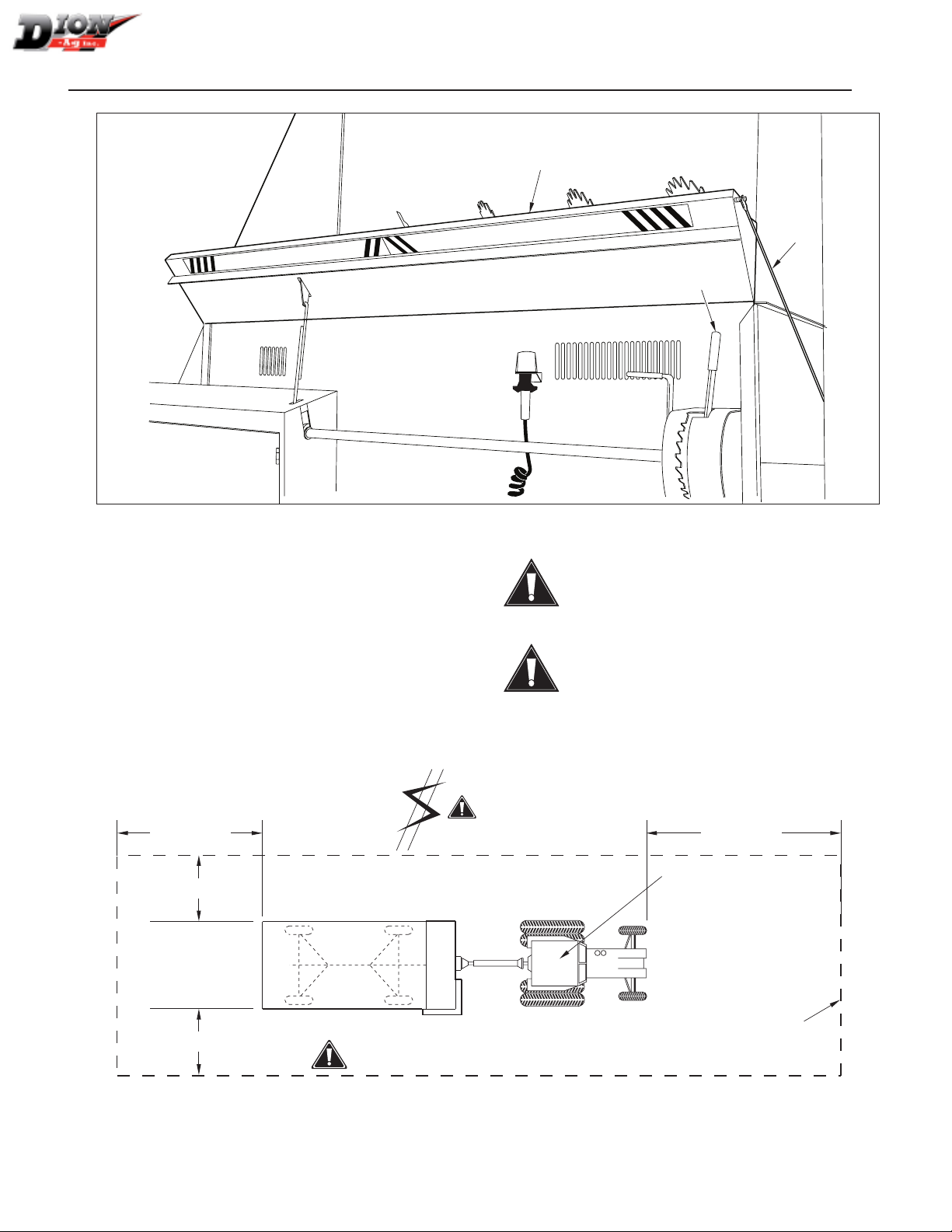
EMERGENCY STOPPING PROCEDURE
FIGURE 1
1. Push on the Emergency Stop push bar (item 1) or
pull on the Emergency Stop Trip cables (item 2).
2. Place the transmission (item 3) in neutral, as shown.
3. Disengage the tractor power-take-off (PTO).
4. Stop the tractor engine.
5. Engage the tractor parking brake.
6. Wait until all rotating parts are totally stopped.
7. Remove the PTO from tractor output shaft.
8. Block all equipment wheels.
DANGER: Rotating driveline contact may
cause serious injury or death.
WARNING: The emergency stop will not stop
the Forage Box when it is operating the rear
unloading mode.
HYDRAULIC OPERATION
(FRONT UNLOADING)
Stay clear of hydraulic lines and fittings. They may be
under extreme pressure or heat.
CAUTION: High pressure oil can puncture skin,
causing serious injuries and infections. So al-
ways lower load or relieve hydraulic pressure
before loosening ttings. Hydraulic uid leaks
may not be visible. Use a piece of cardboard or
wood to nd a leak. Do not use nger or skin
to check for leaks. Wear safety goggles and
gloves at all times
.
DANGER: Before leaving the work area of the
tower silo, always make sure the blower is not
rotating and the tractor powering it is well se-
cured.
Manual No. B5818E983 V1.0
SAFETY RULES
13
RECOMMENDED WORK AREA
REAR UNLOADING - FIGURE 2
This diagram shows the recommended work area. It
should be marked off with colored nylon or plastic ropes
hung as portable barriers to define exactly the designed
work areas.
WARNING: To prevent personal injuries, under
no circumstances, any person not involved in
the operation should be allowed to trespass
into the working area.
WARNING Before the start and during opera-
tion, it is the responsibility of all operators to
make sure the work area is smooth, clean and
free of all debris and tools that may cause ac-
cidental falls.
PUSH TO STOP
POUSSER POUR ARRÊTER
1
3
2
Figure 1 Emergency stop push bar and trip cables
WORK ZONE. KEEP
UNAUTHORIZED PERSONNEL
AT A SAFE DISTANCE
OPERATING ZONE - KEEP CLEAN
OVERHEAD WIRES
KEEP AWAY!
6 ft (2 m)
20 ft (6 m)
6 ft (2 m)
OPERATOR MUST STAY
SEATED ON TRACTOR
DURING UNLOADING
50 ft (16 m)
Figure 2 Typical work area diagram
Manual No. B5818E983 V1.0
SAFETY RULES
14
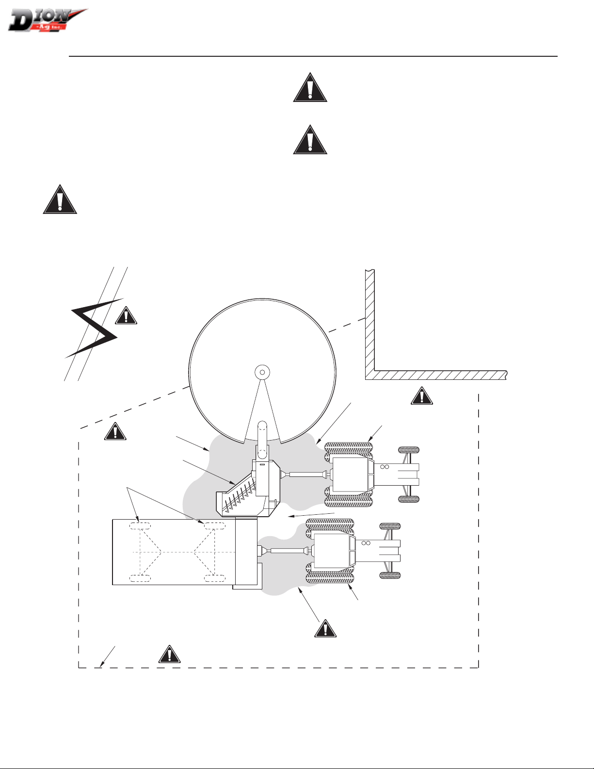
RECOMMENDED WORK AREA AT THE
TOWER SILO
FRONT UNLOADING - FIGURE 3
This diagram shows the recommended work area. It
should be marked off with colored nylon or plastic ropes
hung as portable barriers to define exactly the designed
work areas.
DANGER Before leaving the work area at the
tower silo, always make sure the blower is not
in motion et the tractor powering the blower is
well secured.
WARNING: To prevent personal injuries, under
no circumstances, any person not involved in
the operation should be allowed to trespass
into the working area.
WARNING: Before the start and during opera-
tion, it is the responsibility of all operators to
make sure the work area is smooth, clean and
free of all debris and tools that may cause ac-
cidental falls.
WORKING AREA
OPERATING ZONE: KEEP CLEAN
PTO DRIVE AREA
PTO DRIVE AREA
AUGER INTAKE AREA
OVERHEAD WIRES
KEEP AWAY!
WHEEL CHECKS
WHEEL CHECKS
WHEEL CHECKS
OPERATOR AREA
BLOWER
SILO BARN
Figure 3 Diagram of a typical work area at the tower silo
Manual No. B5818E983 V1.0

SAFETY DECALS
15
SAFETY DECALS
FIGURE 4 TO FIGURE 9
NOTE: AIl machinery safety signs should be kept as clean
as possible, free of dust and easy to read at all
times.
NOTE: When safety signs are worn, or if the machine is
being repainted, order the decal complete kit.
SAFETY SIGNS APPLICATION
PROCEDURE
1. The surface should be free from dirt, grease, earth,
or any other foreign material.
2. When the surface is dry, apply the safety sign in part
and align its position as per the surrounding parts.
Peel off slowly the remaining backing paper and ap-
ply hand pressure.
3. Press (burnish) slightly on the surface to remove all
air bubbles.
Figure 4 Safety decals
Manual No. B5818E983 V1.0

SAFETY DECALS
16
9
11
6
12
9
10
9
458
3
1
1
15
17 18” CONVEYOR
115
7
9
6
Figure 5 Safety decals - Front and combo unloading
9
14
14
Figure 6 Safety decals - Front unloading
13
14
14
11 6
Figure 7 Safety decals - Rear and combo unloading
Note: Decals 11, 12 and 16
are only used on the Combo
and rear unloading models.
Manual No. B5818E983 V1.0

SAFETY DECALS
17
9
15
15 16
11 12 54
Figure 8 Safety decals - Rear unloading
6
15
Figure 9 Safety decals - Rear unloading
Manual No. B5818E983 V1.0

INSTALLATION
18
INSTALLING THE SHORT SIDE
CONVEYOR EXTENSION
FIGURE 10, FIGURE 11 AND FIGURE 12
NOTE: These parts are installed on the Forage Box in the
shipping position, on the assembly line.
1. Install the two holding brackets (item 1) on each
side as shown below. Use three carriage bolts (item
2) and three lock nuts (item 3) on each side.
2. Install the conveyor extension (item 4) by sliding
each end of the conveyor shaft inside bracket slots
(item 1).
3. Slide threaded rods (item 5) inside shaft holes and
lock the nuts on each side of shaft.
4. Position nuts (item 6) as shown in figure 1.
1
4
2
3
1
5
7
Figure 10 Installing the short side conveyor extension
Manual No. B5818E983 V1.0
INSTALLATION
19
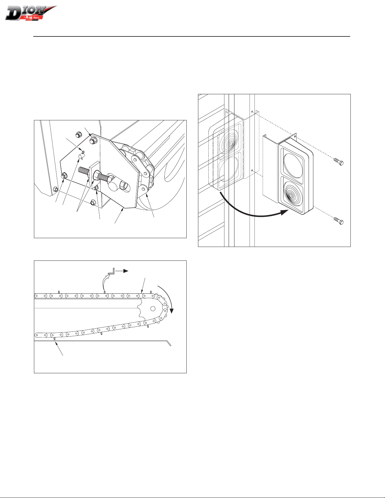
5.
Insert the support rod (item 7) under the conveyor
extension plate (item 4) and secure it with cutter
pins (item 8).
6. Install the conveyor chain (item 9). The back of the
laths should face the exit as shown in figure 12
7. Adjust the conveyor tension. The third lath (item
10) should be the first lath to touch the bottom. Use
nuts (item 6) on both sides to adjust the conveyor
tension.
1
9
6
7
3
3
3
8
Figure 11 Installing the short side conveyor extension
10
9
Figure 12 Installing the short side conveyor extension
SETTING UP THE SIDELIGHTS
FIGURE 13
The sidelights are already installed in a transporting po-
sition on both sides of the Forage Box. Set up the two
lights in the operating position as shown below.
Figure 13 Setting up the sidelights
Manual No. B5818E983 V1.0

INSTALLATION
20
INSTALLING THE 18” SIDE CONVEYOR
EXTENSION (OPTIONAL) - FIGURE 14
1. Remove existing side extension. Keep all bolts
washers and nuts.
2. Install the plate (item 11) with four 3/8” X 1” Lg car-
riage bolts and four 3/8” nuts.
3. Bolt the conveyor extension (item 1) to the side of
the Forage Box as shown. Use ten bolts, lock wash-
ers and nuts (item 2) on each side of the conveyor
4. Install spring (item 3) as shown.
5. Add washers (item 5) between frame and side con-
veyor (on both sides) to keep frame from bending
in.
6. Install spring (item 8) on lock handle (item 9).
7. Follow the same steps for the installation of the
short extension at the end of the 18” extension.
8. Install the conveyor chain extension (item 4). The
back of the laths should face the exit.
9. Adjust the conveyor tension. The third lath should
be the first lath to touch the bottom. Use the 1/2”
nuts (item 6) on both sides to adjust the conveyor
tension
10. Install both chain guides (item 7). Use two bolts
and one washer (item 10). The washer has to be
installed with the upper bolt.
IMPORTANT! Always lower the conveyor before acti-
vating it.
CAUTION! Always raise and lock side convey-
or in transporting position when travelling.
5
4
1
3
6
11
2
7
9
10
8
Figure 14 18” conveyor extension (L.H. unloading Box shown here)
Manual No. B5818E983 V1.0
Table of contents


