1 x 5,5 kW for 2 operators Code B100ST – B125ST
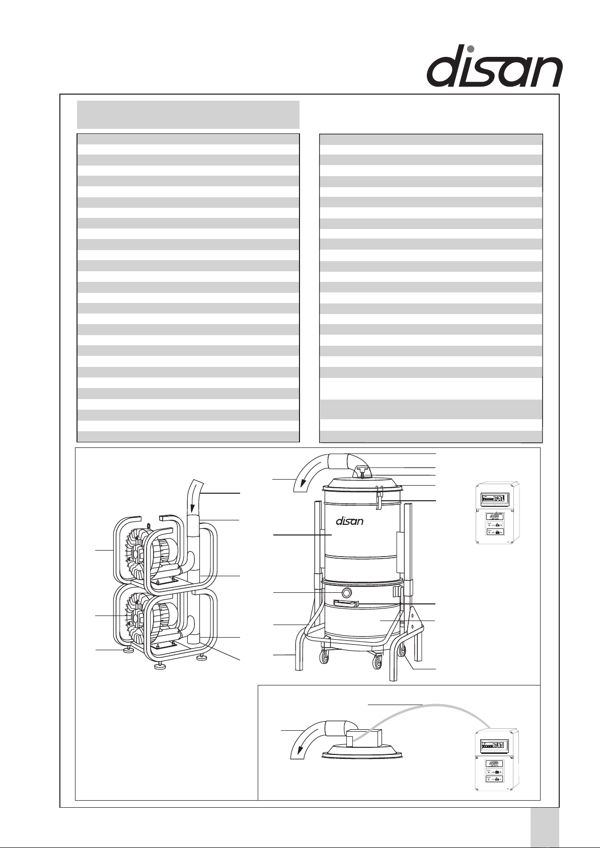
Central vacuum cleaner consisting of:
- one silenced SIEMENS turbine with three-phase side
channel motor without transmission, secured on a
metal frame, IP55 safety degree;
- cyclonic dust separator in steel, painted with epoxy
powder, secured on a metal frame, filter chamber
equipped with industrial-conceived star filter made of
special polyester cloth with high withholding proper-
ties, deflector for the mechanical-gravitational separa-
tion of dust, dirt receptacle on wheels with disposable
plastic bags and cushioned fasteners, safety and
compensation system in the dust bag, manual filter
shaker;
- electric control box with IP55 safety degree, realized in
accordance with CEI norms, with low-voltage (12 V)
outlet and equipped with electric chart for linkage;
- connections for correct linkage to the piping network
and all other parts and accessories for the profession-
al setting of the system;
- CE certificate.
1 x 2,2 kW for 1 operator Code A100 – A125
Central vacuum cleaner consisting of:
- one silenced SIEMENS turbine with three-phase side
channel motor without transmission, secured on a
metal frame, IP55 safety degree;
- cyclonic dust separator in steel, painted with epoxy
powder, secured on a metal frame, filter chamber
equipped with industrial-conceived star filter made of
special polyester cloth with high withholding proper-
ties, deflector for the mechanical-gravitational separa-
tion of dust, dirt receptacle on wheels with disposable
plastic bags and cushioned fasteners, safety and
compensation system in the dust bag, manual filter
shaker;
- electric control box with IP56 safety degree, realized
in accordance with CEI norms, with low-voltage (12 V)
outlet and equipped with electric chart for linkage;
- connections for correct linkage to the piping network
and all other parts and accessories for the profession-
al setting of the system;
- CE certificate.
6
Central Vacuum Systems
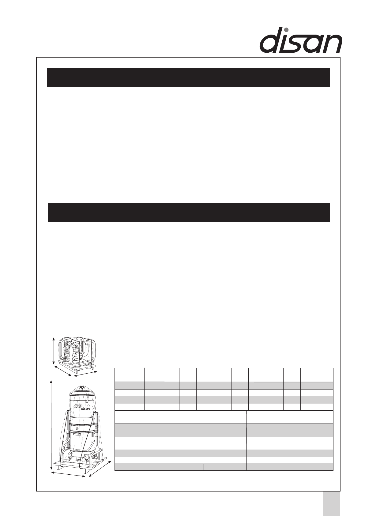
CHARACTERISTICS OF THE CENTRAL VACUUM
CLEANER AND MAIN PARTS
Central vacuum cleaner
model DS A01 100l – 125l
Central vacuum cleaner
model DS B01 100 l – 125 l
Central vacuum cleaner
model DS B02 100 l - 125 l
2 x 2,2 kW for 2 operators Code B200 – B225
Central vacuum cleaner consisting of:
- Two silenced SIEMENS turbines with three-phase side
channel motor without transmission, secured on a metal
frame, IP55 safety degree;
- cyclonic dust separator in steel, painted with epoxy
powder, secured on a metal frame, filter chamber
equipped with industrial-conceived star filter made of
special polyester cloth with high withholding proper-
ties, deflector for the mechanical-gravitational
separa-
tion of dust, dirt receptacle on wheels with disposable
Central vacuum cleaner
model DS BC 100i
1 x 4,5 kW for 2+1 operators Code BC100i
Central vacuum cleaner consisting of:
- one silenced SIEMENS turbine with three-phase side
channel motor without transmission, secured on a
metal frame;
- electronic inverter for continuous modulation of the
frequency and the other motor parameters with
electromagnetic shielding of type B (for applications
within the private and the industrial sector)
- cyclonic dust separator in steel, painted with epoxy
powder, secured on a metal frame, filter chamber
equipped with industrial-conceived star filter made of
special polyester cloth with high withholding proper-
ties, deflector for the mechanical-gravitational separa-
tion of dust, dirt receptacle on wheels with disposable
plastic bags and cushioned fasteners, safety and
compensation valves, arranged for pressure compen-
sation system in the dust bag;
- automatic self-cleaning filter device through program-
mable shaking device;
- electric control box with IP55 safety degree, realized
in accordance with CEI norms, with low-voltage (12 V)
outlet and equipped with electric chart for linkage;
- Ø70 metal muffler for low noise level;
- connections for correct linkage to the piping network
and all other parts and accessories for the profession-
al setting of the system;
- CE certificate.
+
Central vacuum cleaner
model DS C03 100 l – 125
3 x 2,2 kW for 3 operators Code C100 – C125
Central vacuum cleaner composed of:
- three silenced SIEMENS turbines with three-phase
side channel motor without transmission, secured on
a metal frame, IP55 safety degree;
- cyclonic dust separator in steel, painted with epoxy
powder, secured on a metal frame, filter chamber
equipped with industrial-conceived star filter made of
special polyester cloth with high withholding proper-
ties, deflector for the mechanical-gravitational separa-
tion of dust, dirt receptacle on wheels with disposable
plastic bags and cushioned fasteners, safety and
compensation valves, arranged for pressure compen-
sation system in the dust bag, manual filter shaker;
- electric control box with IP55 safety degree, realized
in accordance with CEI norms, with low-voltage (12 V)
outlet and equipped with electric chart for linkage;
- connections for correct linkage to the piping network
and all other parts and accessories for the profession-
al setting of the system;
- CE certificate.
plastic bags and cushioned fasteners, safety and
compensation valves, arranged for pressure compen-
sation system in the dust bag, manual filter shaker;
- electric control box with IP55 safety degree, realized in
accordance with CEI norms, with low-voltage (12 V) outlet
and equipped with electric chart for linkage;
- connections for correct linkage to the piping network
and all other parts and accessories for the profession-
al setting of the system;
- CE certificate.
7
Central Vacuum Systems
Central vacuum cleaner
model DS CD 125i
1 x 5,5 kW for 3+1 operators Code CD125i
Central vacuum cleaner consisting of:
- one silenced SIEMENS turbine with three-phase side channel motor
without transmission, secured on a metal frame;
- electronic inverter for continuous modulation of the frequency from 34
to 84 Hertz with electromagnetic shielding of type B (for applications
within the private and the industrial sector);
- cyclonic dust separator in steel, painted with epoxy powder, secured
on a metal frame, filter chamber equipped with industrial-conceived
star filter made of special polyester cloth with high withholding
properties, deflector for the mechanical-gravitational separation of
dust, dirt receptacle on wheels with disposable plastic bags and
cushioned fasteners, safety and compensation valves, arranged for
pressure compensation system in the dust bag;
- automatic self-cleaning filter device through programmable shaking
device;
- electric control box with IP55 safety degree, realized in accordance
with CEI norms, with low-voltage (12 V) outlet and equipped with
electric chart for linkage;
- Ø100 metal muffler for low noise level
- connections for correct linkage to the piping network and all other
parts and accessories for the professional setting of the system;
- CE certificate.
+
3 x 5,5 kW for 6 operators Code F125ST
Central vacuum cleaner consisting of:
- three silenced SIEMENS turbines with three-phase side channel
motor without transmission, star-triangle starting, secured on a metal
frame, IP55 safety degree;
- cyclonic dust separator in steel, painted with epoxy powder, secured
on a metal frame, filter chamber equipped with industrial-conceived
star filter made of special polyester cloth with high withholding
properties, deflector for the mechanical-gravitational separation of
dust, dirt receptacle on wheels with disposable plastic bags and
cushioned fasteners, safety and compensation valves, arranged for
pressure compensation system in the dust bag, manual filter shaker
predisposed for self-cleaning filter device;
- electric control box with IP55 safety degree, realized in accordance
with CEI norms, with low-voltage (12 V) outlet and equipped with
electric chart for linkage;
- connections for correct linkage to the piping network and all other
parts and accessories for the professional setting of the system;
- CE certificate.
Central vacuum cleaner
model DS F03 125 l
2 x 7,5 kW for 8 operators Code H175ST
Central vacuum cleaner consisting of:
- two silenced double-V shaped SIEMENS turbines with three-phase
side channel motor without transmission, star-triangle starting,
secured on a metal frame, IP55 safety degree;
- cyclonic dust separator in steel, painted with epoxy powder, secured
on a metal frame, filter chamber equipped with industrial-conceived
star filter made of special polyester cloth with high withholding
properties, deflector for the mechanical-gravitational separation of
dust, dirt receptacle on wheels with disposable plastic bags and
cushioned fasteners, safety and compensation valves, arranged for
pressure compensation system in the dust bag, manual filter shaker
predisposed for self-cleaning filter device;
- electric control box with IP55 safety degree, realized in accordance
with CEI norms, with low-voltage (12 V) outlet and equipped with
electric chart for linkage;
- connections for correct linkage to the piping network and all other
parts and accessories for the professional setting of the system;
- CE certificate.
Central vacuum cleaner
model DS H02 175 l
Central vacuum cleaner
model DS D02 100 l - 125 l
2 x 5,5 kW for 4 operators Code D100 – D125
Central vacuum cleaner consisting of:
- two silenced SIEMENS turbines with three-phase side channel motor
without transmission, star-triangle starting, secured on a metal frame,
IP55 safety degree;
- cyclonic dust separator in steel, painted with epoxy powder, secured
on a metal frame, filter chamber equipped with industrial-conceived
star filter made of special polyester cloth with high withholding
properties, deflector for the mechanical-gravitational separation of
dust, dirt receptacle on wheels with disposable plastic bags and
cushioned fasteners, safety and compensation valves, arranged for
pressure compensation system in the dust bag, manual filter shaker;
- electric control box with IP55 safety degree, realized in accordance
with CEI norms, with low-voltage (12 V) outlet and equipped with
electric chart for linkage;
- connections for correct linkage to the piping network and all other
parts and accessories for the professional setting of the system;
- CE certificate.
Central vacuum cleaner
model DS CD 125i
1 x 7,5 kW for 5+1 operators Code EF125i
Central vacuum cleaner consisting of:
- one silenced SIEMENS turbine with three-phase side channel motor
without transmission, secured on a metal frame;
- electronic inverter for continuous modulation of the frequency from 34
to 84 Hertz with electromagnetic shielding of type B (for applications
within the private and the industrial sector);
- cyclonic dust separator in steel, painted with epoxy powder, secured
on a metal frame, filter chamber equipped with industrial-conceived
star filter made of special polyester cloth with high withholding
properties, deflector for the mechanical-gravitational separation of
dust, dirt receptacle on wheels with disposable plastic bags and
cushioned fasteners, safety and compensation valves, arranged for
pressure compensation system in the dust bag;
- automatic self-cleaning filter device through programmable shaking
device;
- electric control box with IP55 safety degree, realized in accordance
with CEI norms, with low-voltage (12 V) outlet and equipped with
electric chart for linkage;
- Ø100 metal muffler for low noise level
+
1x11kW for 8+1 operators Code HK175i
Central vacuum cleaner consisting of:
- one silenced double-V shaped SIEMENS turbine with three-phase
side channel motor without transmission, secured on a metal frame;
- electronic inverter for continuous modulation of the frequency from 34
to 84 Hz with electromagnetic shielding type B;
- cyclonic dust separator in steel, painted with epoxy powder, secured on
a metal frame, filter chamber equipped with industrial-conceived star
filter made of special polyester cloth with high withholding properties,
deflector for the mechanical-gravitational separation of dust, dirt
receptacle on wheels with disposable plastic bags and cushioned
fasteners, safety and compensation valves, arranged for pressure
compensation system in the dust bag;
- automatic self-cleaning filter device through programmable shaking
device;
- electric control box with IP55 safety degree, realized in accordance
with CEI norms, with low-voltage (12 V) outlet and equipped with
electric chart for linkage;
- double Ø'3f100 metal muffler for low noise level;
- connections for correct linkage to the piping network and all other parts
and accessories for the professional setting of the system.
Central vacuum cleaner
model DS HK175i
+
- connections for correct linkage to the piping network and all other
parts and accessories for the professional setting of the system;
- CE certificate.