manuals.online logo
Brands
  1. Home
  2. •
  3. Brands
  4. •
  5. displayit
  6. •
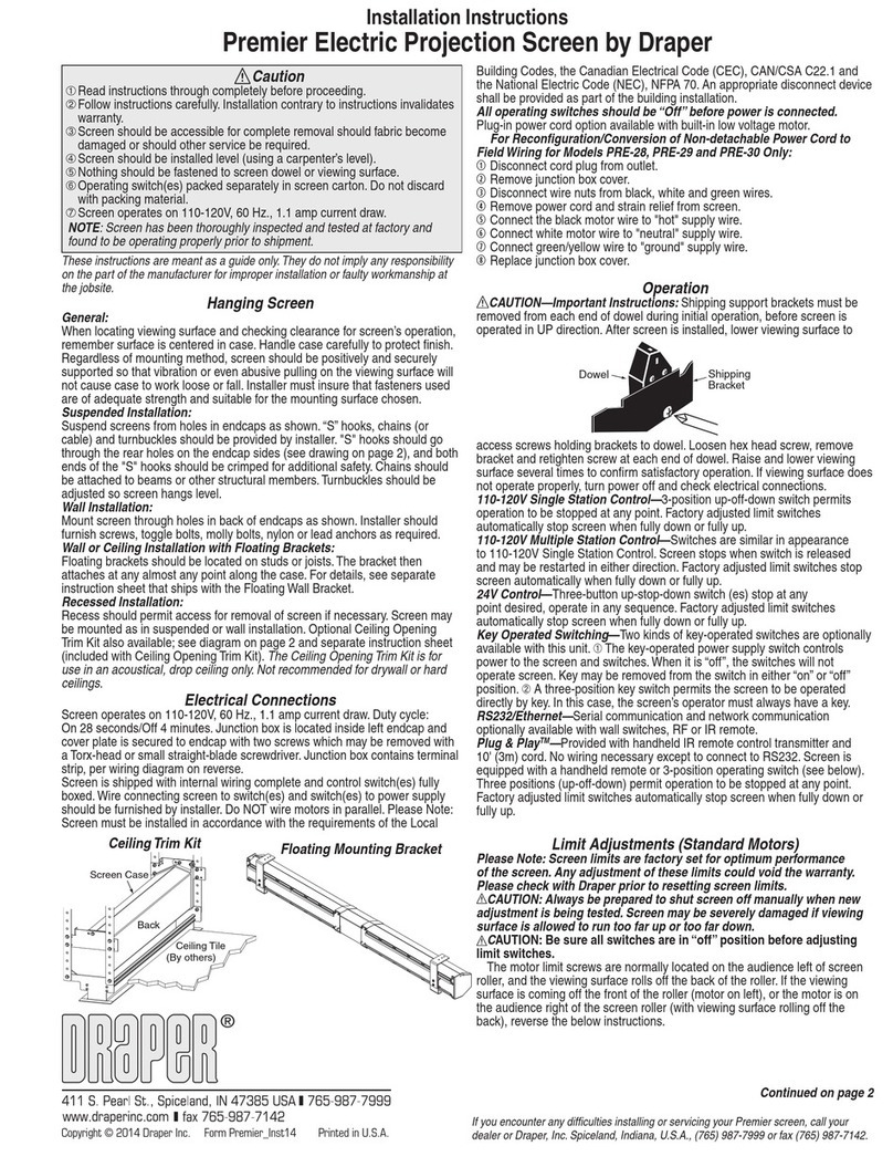
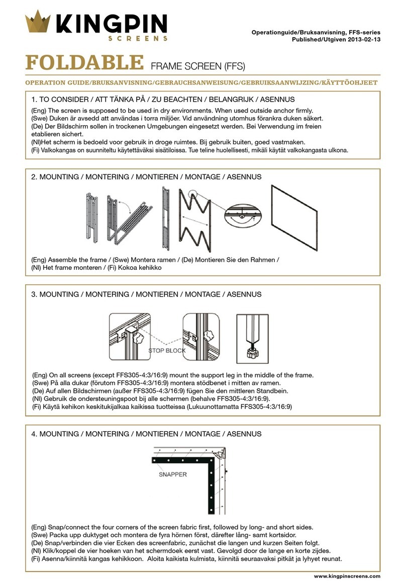
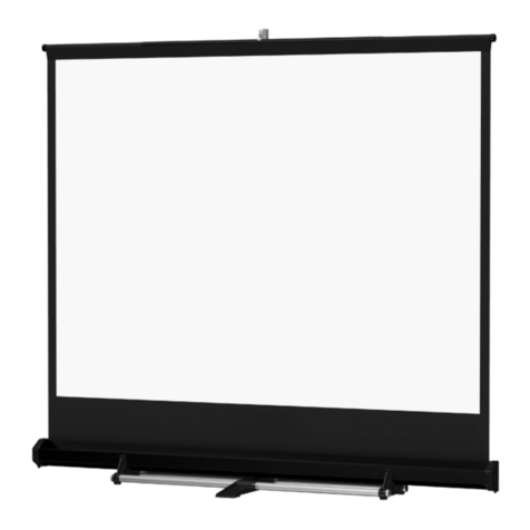
  7. Projection Screen
  8. •
  9. displayit Flare User manual

displayit Flare User manual

20’ (230” x 92”) Flare
displayit.com 800.207.0311 After-Hours Emergency: Call or Text 678.723.5343
Flare v3.2 Updated 9/4/2019
Assembly Instructions Page 1
Parts List
14 - Frame perimeter pieces
(See Diagram 1 for details)
10 -
Flat Connecting Brackets with Wing Nuts
4 - Corner Brackets with Wing Nuts
4 - Extra Wing Nuts
(1/4-20 Thread Size)
3 - Vertical Support Sets
(1 Set includes two poles and a plastic lock tube)
2 - Flare Spacing Rulers (Side A and Side B)
8 - Double-Sided Curtain Lights
8 - Power Supplies with Velcro (100 Watts)
36 - Light Mount Clips*
2 - 10 Foot Power Cords with 5 Quick-Connects
6 - Wire Management Clips
5 - Flare Feet
12 - T-Bolts for Flare Feet*
12 - Washer Wing Nuts for Flare Feet*
(1/4-20 Thread Size)
SIDE A
SIDE B
* Includes extras provided
Need Help?
Scan the QR code or go to
displayit.com/flare-guide
to watch an assembly video.
20’ (230” x 92”) Flare
displayit.com 800.207.0311 After-Hours Emergency: Call or Text 678.723.5343
Flare v3.2 Updated 9/4/2019
Assembly Instructions Page 2
CAUTION:
METAL EDGES
MAY BE SHARP
Diagram 1
46” SIDE
CORNER
46” TOP
CORNER
46” TOP
CORNER
46” SIDE
CORNER
46” SIDE
CORNER
46” SIDE
CORNER
46” BOTTOM
CORNER
46” BOTTOM
CENTER
B
Foot Holes
46” BOTTOM
CORNER
Foot
Holes
46” TOP
CENTER
B
46” TOP
CENTER
A
46” TOP
CENTER
C
Wire
Pass-through
46” BOTTOM
CENTER
A
Foot Holes
46” BOTTOM
CENTER
C
Foot Holes
Foot
Holes
Wire
Pass-through
Velcro for Power Supplies
Future Support Pole
Locations
Corner with Longer Leg
Note: It’s best to build the
frame laying on its back.
1. Upack the frame. Save all foam pieces for repacking later. Lay out the frame pieces as seen in Diagram 1.
Frame perimeter pieces are labeled with stickers matching Diagram 1 to make this step easier.
Take note where the velcro strips for the power supplies are located on Diagram 1.
Assemble the frame on its back.
2. Assemble frame top,
bottom, and sides using
six flat connecting brackets.
Hand tighten wing nuts to
secure.
4. Complete the frame
perimeter build by attaching
the top horizontals with top
corner brackets.
Frame SideFrame Side
Frame TopFrame Top
3. Connect the frame sides to the
frame bottom with two corner
brackets. Make sure the longer legs
of the corner brackets run along
the bottom frame piece. The holes
in the longer legs align with the
foot holes in the bottom of the
frame. Hand-tighten the wingnuts.
Longer Legs
Align with
Foot Holes
Frame SideFrame Side
Frame BottomFrame Bottom
20’ (230” x 92”) Flare
displayit.com 800.207.0311 After-Hours Emergency: Call or Text 678.723.5343
Flare v3.2 Updated 9/4/2019
Assembly Instructions Page 3
Diagram 3
5. Unroll the included spacing rulers and
place them on the ground inside the
frame. Overlap the two rulers aligning
the blue lines marked “Center foot
holes.” Align the foot lines on the ruler to
the foot holes in the frame.
Use the ruler to locate the recommended
placement for the support poles, curtain
lights, and power supplies.
6. Install each suport pole as noted on the ruler (Diagram 2).
A. Hook top hook into frame channel and swing down to vertical.
B. Repeat for the bottom pole until they meet in the middle.
C. Press the push-button and slide the lock tube over the end of the
other pole half until the button clicks.
Ruler Side B
Ruler Side A
Rulers Overlapped
Green Line Aligned with
Center Foot Holes
Top of Frame Bottom of Frame
Pole with push-button
and tube lock
Pole without tube lock
Diagram 2
Press
Slide
Lock Tube
Lock Tube
Spacing Ruler Side A
Overlapped Spacing Ruler Side B
20’ (230” x 92”) Flare
displayit.com 800.207.0311 After-Hours Emergency: Call or Text 678.723.5343
Flare v3.2 Updated 9/4/2019
11. Attach feet using t-bolts and wing nuts.
Each t-bolt goes through a counterbored hole in the foot, then
through a hole in the metal frame.
For the corner feet, each t-bolt then passes through the corner
bracket. Secure each t-bolt with a washer wing nut.
Hand-tighten until snug; do not over-tighten.
12. To help stop wire shadows on the graphic, use the
provided snap-on wire management clips. The curtain light
clips may also be used for wire management.
11. With at least two people, carefully stand the display
up. Inspect the connections between frame pieces. If
any gaps occured when smoving the frame, loosen the
wing-nuts, press the frame back together, and retighten
the wingnuts.
Counterbored holes
Assembly Instructions Page 4
8. Attach the power supplies to the frame via the velcro
strips and connect the wires to the curtain lights.
9. Run each main power cable through the wire
pass-throughs. Connect all power supplies to the cords
starting with the transformers in the middle of the display.
Four transformers will connect to each power cable.
Plug the cables into an AC outlet to test the lights.
7. Attach the bottom of the curtain light to the center
channel of the frame using light clips (Diagram 3).
To attach clips, hook each clip through the wire loop.
Squeeze clip, insert into channel, and release.
Suggested light clip locations are marked on the ruler.
Carefully unroll the curtain light and clip the top clips
into the top of the frame, keeping the wires straight.
Center Channel
20’ (230” x 92”) Flare
displayit.com 800.207.0311 After-Hours Emergency: Call or Text 678.723.5343
Flare v3.2 Updated 9/4/2019
Assembly Instructions Page 5
1. Using at least two people,
carefully stand the display up.
Starting in top-left corner, turn
and tuck graphic and silicone
into the channel. (#1 on diagram)
Use your fingertip (not fingernail)
for installation.
Note: For large frames, a step ladder
may be required for graphic installation.
2. Work across the top, tacking the graphic into the channel
every two to three feet. (#2 on diagram)
3. Tuck top, right corner into channel. (#3 on diagram)
4. Tuck remainder of top edge of graphic into top channel.
(#4 on diagram)
5. Inspect graphic for hard fold lines in the fabric.
If desired, smooth them out using a fabric steamer.
6. Tuck bottom two corners. (#6 on diagram)
7. Tack middle of sides. (#7 on diagram)
8. Working from top to bottom, tuck remaining silicone in
on both sides. (#8 on diagram)
9. Tack middle of bottom. (#9 on diagram)
10. Tuck remaining bottom edge, working from outside to
inside. (#10 on diagram)
11. Repeat installation steps for fabric on back of frame.
1 2 2 2 3
6 6
77
44
91010
88
Fabric
Graphic
Silicone Welt
(On Back)
Graphic Installation
Silicone
Silicone
Fabric
Fabric
Top of Frame
Caution! Installing silicone-edged graphics is techniqe sensitive;
Practice will shorten installation time.
Handle graphics with care with clean hands in a clean environment.
Cloth or latex gloves recommended.
Keep graphics away from sharp objects.
20’ (230” x 92”) Flare
displayit.com 800.207.0311 After-Hours Emergency: Call or Text 678.723.5343
Flare v3.2 Updated 9/4/2019
1. Carefully lay two curtain lights
on top each other and roll them
up together.
Wrap foam around the
roll.
3. Vertical support poles go
into box #3.
4. Pack the small hardware
items into the two canvas
bags. These bags along
with the feet, power
supplies, and power cord
fit into the final box.
Assembly Instructions Page 6
Packing Instructions
Failure to follow packing instructions
may result in damaged items.
!
Two curtain lights stacked
Frame perimeter metal pieces with foam between
Box #3 - Round Support Poles
Box #1 - 4 Curtain Lights Box #2 - 4 Curtain Lights
Box #4 - Power Supplies, Feet,
wires, & Small Hardware
Short foam
on ends Short foam
on ends
5. Frame perimeter pieces pack on their edge with foam between.
6. After all hardware is in the case, put a foam sheet on top.
7. Fold the graphics up and place them into plastic bags.
Store them in the case on the top level above the foam sheet.
2A. Insert the vertical support
pole into one of the boxes.
2B. Insert one double curtain roll
into the bottom of the box.
2C. Put the second double
curtain roll in the top of the box.
2D. Repeat to pack the last four
curtain lights in the second box.

Other displayit Projection Screen manuals
displayit Elements User manual

displayit

displayit Elements User manual
displayit 1010A-01 User manual

displayit

displayit 1010A-01 User manual
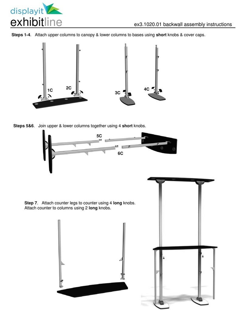
displayit exhibitline User manual

displayit

displayit exhibitline User manual

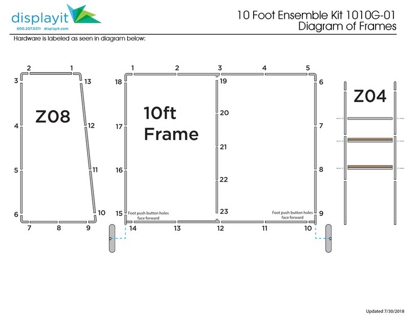
displayit 1010G-01 User manual

displayit

displayit 1010G-01 User manual

displayit 10 Foot User manual

displayit

displayit 10 Foot User manual
displayit Elements User manual

displayit

displayit Elements User manual

displayit 5 Foot User manual

displayit

displayit 5 Foot User manual

displayit 1020A-01 User manual

displayit

displayit 1020A-01 User manual
Popular Projection Screen manuals by other brands
Optoma Panoview DS-3072PMG owner's manual

Optoma

Optoma Panoview DS-3072PMG owner's manual

promethean TP-1982-ML-V03 Installation and user guide

promethean

promethean TP-1982-ML-V03 Installation and user guide

Absen iCon Series user manual

Absen

Absen iCon Series user manual

Elite Screens Evanesce B Series user guide

Elite Screens

Elite Screens Evanesce B Series user guide

X-METAL 37912 Assembly instructions

X-METAL

X-METAL 37912 Assembly instructions

Rehau RELAZZO Assembly instructions

Rehau

Rehau RELAZZO Assembly instructions

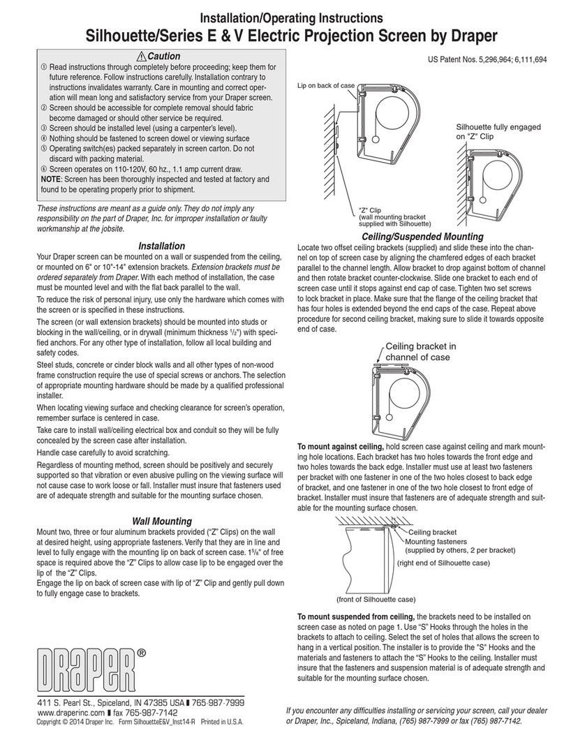
Draper Signature E Series Installation & operating instructions
Draper

Draper Signature E Series Installation & operating instructions

FART PRODUKT Standard SCREEN Installation instruction

FART PRODUKT

FART PRODUKT Standard SCREEN Installation instruction

Stewart Audio AT 3.0 owner's manual

Stewart Audio

Stewart Audio AT 3.0 owner's manual

Classic Exhibits Perfect 10 VK-1400 manual

Classic Exhibits

Classic Exhibits Perfect 10 VK-1400 manual

Elite Screens Ez-Frame Series user guide

Elite Screens

Elite Screens Ez-Frame Series user guide

Elite Screens Manual Series user guide

Elite Screens

Elite Screens Manual Series user guide

Draper Paragon Installation and operating instructions

Draper

Draper Paragon Installation and operating instructions

Screen Research MMS2-L1 installation manual

Screen Research

Screen Research MMS2-L1 installation manual

Akuart SS50 instruction manual

Akuart

Akuart SS50 instruction manual

EPV PowerMax Tension Series user guide

EPV

EPV PowerMax Tension Series user guide

Oray Cineflex CFX01 quick guide

Oray

Oray Cineflex CFX01 quick guide

Banner EZ-SCREEN LS instruction manual

Banner

Banner EZ-SCREEN LS instruction manual

manuals.online logo
manuals.online logoBrands
  • About & Mission
  • Contact us
  • Privacy Policy
  • Terms and Conditions

Copyright 2025 Manuals.Online. All Rights Reserved.